
Exploratory Studies on Silicon-Based Oxide Fuel Cell Power Sources Incorporating Ultrathin Nanostructured Platinum and Cerium Oxide Films as Anode Components
School of Engineering and Applied Sciences, Harvard University Cambridge, MA 02138, U.S.A.
1. Introduction
Solid oxide fuel cells (SOFCs) convert chemical energy from hydrogen or hydrocarbons into electrical energy with high power density, high energy efficiency, and low carbon footprints. Their potential applications could cover the span from large-scale power plants to portable electronics.1,2 SOFCs that are of small form factor and can be manufactured at low cost have increasingly attracted research attention.2-10 Such SOFCs are usually referred to as micro (μ) or thin-film (TF) SOFCs because of their small form factor and/or the microfabrication and thin film deposition techniques employed.8,11 In addition, TFSOFCs may also serve as model systems to elucidate the roles of thickness, microstructure, surfaces, and interfaces in further enhancing performance of intermediate- and low-temperature SOFCs.12-18
The primary physical structure of a TFSOFC is a membrane consisting at least three layers of sub-μm thin films – namely, cathode, electrolyte, and anode. During SOFC operation, oxygen molecules are reduced to oxygen ions on cathode surface or triple phase boundaries (TPBs.) The oxygen ions are then transported (via ion-vacancy exchange) through electrolyte and anode to combine with hydrogen on anode surface or at TPBs. The charge flow of oxygen ions from cathode to anode is accompanied with a current flow of electrons from anode to cathode through the external circuit. The overall performance of the hetero-structures is extremely sensitive to properties of each layer and interfaces between layers.
In the past decade, development of TFSOFCs3 has evolved from micro-fabrication of thermomechanically stable yttria-stabilized zirconia (YSZ) electrolyte membranes,19,20 to implementation of Pt and Pt-based composite cathodes,10,21,22 to the replacement of Pt or Pt-based cathodes with oxide cathodes,2,7,9,11,22,23 as well as performance enhancement by inserting an interlayer between YSZ electrolytes and Pt cathodes or using corrugated membranes.10,24 To date, because of its excellent electrochemical catalytic properties and the lack of satisfactory anode alternatives, pure Pt is still used as the anode for majority of the TFSOFCs reported in the literature.2,7,9,22,24 One specific issue with pure Pt anodes in TFSOFCs is the instability of porous microstructures. In order to increase area of TPBs, at which oxygen reduction occurs, Pt is usually deposited at high pressure and annealed at elevated temperatures to yield a porous microstructure. However, as reported in Refs. 9, 10, and 21, such porous microstructures may not be stable – namely, Pt thin films undergo grain coarsening and then dewetting with increasing temperature. The dewetting effect is due to the capillary instability associated with high surface-to-volume ratioa and has been observed for other ultrathin metal films.25-27 Its occurrence is usually preceded by formation of pores21 in otherwise continuous thin films28,29 and then proceeds until the films agglomerate to form isolated islands.9 As a consequence, the discontinuous Pt thin films become laterally insulating.
Besides further enhancing microstructure stability of Pt thin films, a more critical challenge for TFSOFCs is using an oxide or oxide-based anode to replace Pt or to reduce volume of the Pt used,21 which is important for cost reduction, as well as scientific perspectives. The goal of this article is to report our recent progress in developing microstructurally stable Pt thin films and exploring functional oxides on the anode side of TFSOFCs. Since the thin films could cover electrolyte, Si (or Forturan), and/or Si3N4 surfaces in current fabrication processing of TFSOFCs,2,9,10 it is important to understand behavior of oxide thin films on different surfaces because their properties might be substrate-dependent. For instance, Pt reacts with Si in 200-450 °C range but not with YSZ.30-32 Here, we will focus our efforts on oxide thin films deposited on YSZ and Si3N4 surfaces and characterize their properties that are of direct relevance to TFSOFC performance. The properties investigated include: microstructure, crystallization behavior, film stresses, and electrical conductivity at room temperature (RT). We have also fabricated TFSOFCs based on the thin films studied, while using YSZ as electrolyte and Pt or lanthanum strontium cobalt ferrite (LSCF) as cathodes, to investigate their functionality on the anode side of TFSOFCs.
Unlike metal deposition, oxide materials are relatively difficult to sputter-deposit in a porous form. Therefore, oxides that are suitable for TFSOFC anode applications need to be good ionic and adequate electronic conductors. The former allows oxygen ions from the electrolyte to reach the anode surface via ion-vacancy exchange, while the latter enables electron collection and delivery to the external circuits.33 The oxides we chose to investigate were cerium oxides (ceria, CeOx), despite the fact that undoped ceria has heretofore not been recognized as a promising anode material.34 The advantages of ceria include good mixed conduction and enhanced electronic conduction in nanostructured forms.35,38-40 Enhanced performance of TFSOFCs has been reported when using Gd-doped ceria (GDC) interlayer between the Pt cathode and YSZ electrolyte,10 but it is still unclear if such enhancement can be observed when using GDC or ceria as the anode interlayer.41 Moreover, the mechanisms (ionic conductivity, electronic conductivity and/or reduction activity at the GDC/Pt/air TPBs) responsible for the enhancement are still not well understood. Also, ceria is widely used as matrix or active components in many catalytic composites. Since electrochemical functionality and thermomechanical stability are complex and intertwined phenomena for the anodes in TFSOFCs, investigation of undoped ceria could provide valuable insight and guidance for further electrode research using doped ceria or ceria-based composites.
In this report, we show that microstructural stability of porous Pt thin films can be enhanced by simply increasing its thickness while functional fuel cell performance is still maintained. We also examine the suitability of ceria for the anode side of TFSOFCs. Our results indicate that, when using oxides in TFSOFCs, it is critical to understand temperature-, substrate-, and environment-dependence of phase transition, microstructure change, interfacial reaction, and stress evolution in order to maintain stability and electrochemical functionality of TFSOFC membranes. We anticipate that the results presented here can provide insights and guidance for further anode development using complex oxides or composites for intermediate- or low-temperature SOFCs.
2. Experimental
Porous platinum (Pt) was sputtered at a dc power of 250 W and a pressure of 75 mTorr. Cerium oxides were deposited using a pure cerium (Ce) target without substrate heating. The dc power for the cerium target was 100 W and the process gas, 10 seem of Ar and 10 seem of O2, was maintained at 5 mTorr pressure during sputtering. A custom La0.6Sr0.4Co0.8Fe0.2O3 (LSCF) target and an 8% yttria-doped zirconia (YSZ) target operated at a gun power of 60 W and 100 W, respectively, were used to deposit LSCF and YSZ thin films. Thickness of LSCF thin films was controlled to be in 15-20 nm range to avoid microcracks while maintaining adequate electrical conductivity. Deposition and optimization of LSCF thin films for TFSOFCs applications are described in detail elsewhere.11,23 We used single crystalline YSZ (100) and Si3N4-coated Si wafers as substrates.
Unless otherwise specified, annealing was performed in air for 2 hours at ramping and cooling rates of 5 °C/min in a Thermolyne 21100 tube furnace. Grazing incidence x-ray diffraction (XRD) was performed with a Scintag 2000 diffractometer using Cu Κα radiation at an incidence angle of 1o. Microstructures were investigated by Carl Zeiss Ultra 55 field emission scanning electron microscopy (SEM). Temperature-dependent film stresses were measured by a Toho FLX-2320-S thin film stress measurement system with an identical temperature profile as the annealing experiments. The system measures stress-induced curvature change of 4” substrate wafers prior to and after thin film deposition, with the film stresses determined from Stoney equation.42 Nominal substrate thicknesses of 525 μm and biaxial modulus of 181 GPa for Si were used in the calculation. Lateral electrical conductivity at RT was measured by a Creative Design Engineering ResMap 168 four-point probe resistivity mapping system. TFSOFCs were fabricated by photolithography similar to the procedure described elsewhere and measured using the same apparatus.9
3. Results and discussion
• Pt thin film anode
We deposited Pt thin films with a nominal thickness of 130 nm. This value is thicker than the Pt thin films that suffer dewetting-induced microstructure instability.9,21 Figures l(a)–(e) show SEM images of morphology evolution of 130 nm Pt/YSZ thin films annealed at different temperatures. As seen in Fig. 1(a), because of high deposition pressure, Pt particulates were loosely packed on surface. Upon annealing at 300 °C, size of the particulates slightly increases. A distinct morphology change – namely, coarsening of the particulates – was observed when the films were annealed at 400 °C, as shown in Fig. 1(c), and that continues with further annealing to 500 °C. Upon annealing at 600 °C, gaps between coarsened particulates become narrower and the films form a more continuous and smooth morphology – in other words, the films begin to slightly wet the surface. Similar wetting phenomenon was also observed for the 500 °C-annealed thin film with additional 24 hours of annealing and for thin films annealed in the SOFC operation environment9 – i.e. a flowing gas mixture (5% H2 and 95% Ar) at a rate of 25 seem, see Fig. 1(f).
Effect of annealing temperature on as-deposited Pt/YSZ thin films was further investigated by using the four-point probe measurement. As seen in Fig. 2, the measured electrical conductivity corresponds well to the morphology evolution displayed in Fig. 1. The as-deposited and 300 °C-annealed thin films that exhibit similar morphology possess similar electrical conductivity. When the Pt particulates start to coarsen above 300 °C, electrical conductivity also begins to increase rapidly with increasing temperature. The observed wetting in the 600 °C-annealed, 500 °C-24 hour-annealed, 550 °C-H2-annealed, and 600°C-24 hour-annealed samples leads to electrical conductivity saturation to values that are ~60% of the bulk conductivity (~96.6×l03 S/cm). The results, shown in Figs. l(e)–(f) and 2(a), also indicate that oxidizing or reducing atmosphere during annealing has little effect on the properties of Pt/YSZ thin films.
Compared to similar Pt thin films that were sputtered on Si substrates at high deposition pressure in Ref. 21, our results show that Pt/YSZ thin films also undergo morphology change from particulate coarsening to surface wetting upon annealing. However, the morphology of our Pt/YSZ thin films appears relatively stable when annealed in 500–600 °C range and no sign of dewetting was observed. The difference in morphology at 600 °C is mainly due to the fact that the Pt films in our study are thicker. Different interfacial energy of Pt/Si and Pt/YSZ interfaces and absence of interfacial reactions in the Pt/YSZ system in this temperature range might also be partially responsible for the observations. The result demonstrates that, for Pt/YSZ thin films, it is possible to enhance morphology stability, at the cost of less porosity, by simply increasing film thickness.
One of the central concerns for TFSOFCs is the stress-induced thermomechanical instability in ultra-thin film membranes.19,20 Since morphology evolution at temperatures below 500 °C is similar for both Pt/Si3N4 and Pt/YSZ systems, Pt thin films were deposited onto Si3N4-coated 4” Si wafers using identical deposition parameters as the Pt/YSZ thin films to investigate the temperature-related stress evolution below 500 °C. Fig. 2(b) shows stress evolution of such Pt/Si3N4 thin films. Low film stresses at RT are attributed to the loosely packed Pt particulates. Except for the stress deviation that occurs in 300–420 °C range upon heating, film stresses decrease with increasing temperature due to larger thermal expansion of Pt than Si. The tensile stresses are due to the pulling force between adjacent particulates during coarsening.4
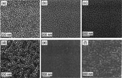
Figure 1. SEM images of Pt/YSZ thin films that were (a) as-deposited without substrate heating, annealed in air at (b) 300 °C, (c) 400 °C, (d) 500 °C, and (e) 600 °C, and (f) annealed in flowing 5% H2 at 550 °C.

Figure 2. (a) RT electrical conductivity of Pt/YSZ thin films annealed at various temperatures for 2 hours in air (■), 24 hours in air (▲), and 2 hours in flowing 5% H2 (o). (b) temperature dependence of film stresses in 130 nm Pt/Si3N4 thin films upon heating (▲) and cooling (v).

Figure 3. (a) Micrographs of TFSOFC array with twelve 100 x 100 μm square membranes on a 10×10 mm Si chip and a close up micrograph for one of the membranes; (b) power density as a function of current density measured at 500 °C.
Performance of TFSOFC array based on 20 nm-LSCF/60 nm-YSZ/130 nm-Pt membranes (LYP, hereafter) was measured by placing a probe at the center of the array. Fig. 3(a) shows a TFSOFC chip that contains twelve 100 x 100 μm square membranes in a circular arrangement. The low open-circuit voltage (OCV) of ~0.32 V of the TFSOFC array is primarily attributed to the probing method we used – namely, the overall OCV is determined by the TFSOFC with the lowest OCV among the twelve. As pointed out in Ref. 22, this probing method could also lead to lower OCV because the 20 nm LSCF cathode might not be conductive enough as the current collector.11 Nevertheless, as seen in Fig. 3(b), our measurements at 500 °C shows an average power density of ~27 mW/cm2 per membrane. Despite the low OCV and insufficient current collection, the power density is only a factor of two lower than our previous measurements on a single TFSOFC using a thinner Pt anode but thicker YSZ electrolyte.9 Therefore, the current results indicate a balance of microstructure stability and TFSOFC performance is achievable by carefully controlling thickness of porous Pt thin films.
• Ceria thin films
We deposited 30 nm CeOx concurrently onto Si3N4 and YSZ substrates, referred to as CeOx/Si3N4 and CeOx/YSZ thin films, respectively. Fig. 4(a) shows XRD patterns of as-deposited and 500 °C-annealed CeOx/Si3N4 thin films, with the corresponding SEM images displayed in Figs. 5(a) and (b), respectively. The as-deposited CeOx/Si3N4 thin films exhibit crystalline CeO2 phases (JCPDS No. 03-065-2975) and a smooth surface morphology. After 500 °C annealing, no change in the phase and morphology was observed except for an angular shift of XRD peaks. The absence of morphology change in the presence of apparent lattice change was also observed in nanocrystalline CeO2-δ on Si and on sapphire.43,44
The shift of XRD peaks towards a higher 2-theta indicates a decrease in the lattice constant. For CeO2-δ, its lattice constant increases linearly with increasing oxygen deficiency because the formation of oxygen vacancies is charge-compensated by a Ce4+ → Ce3+ reduction and the ionic radius of Ce3+ is higher than of Ce4+.43, 45 Since the CeO2-δ thin films were deposited in an oxygen-deficient vacuum environment46 and concentration of oxygen vacancies is inherently higher38 in grain boundaries, vacuum-deposited nanocrystalline CeO2-δ is more deficient in oxygen and hence has a higher lattice constant than its bulk counterpart.47 When annealed in air, oxygen incorporation occurs and leads to a decrease of the lattice constant. Similar phenomena have also been observed for as-deposited YSZ and LSCF thin films.9,11
As seen in the stress evolution plot of Fig. 4(b), the oxygen incorporation likely occurs at ~120 °C and induces a change in the sign of stress/temperature slope from negative to positive. These results are consistent with previous reports on oxygen storage and release at low temperatures.45 However, although thermal expansion of CeO2 is greater than Si, the slope of stress evolution remains positive above 120 °C upon heating. Upon cooling, the stress evolution also does not obey thermal expansion difference in 500–340 °C and 235–155 °C temperature ranges. These results resemble those reported in Ref. 43, for which an unusual lattice parameter change that is independent of thermal expansion difference was observed in nanocrystalline CeO2-δ/Si thin films annealed in 150–450 °C range. Due to the excellent crystal structure and lattice constant matching between ceria and YSZ, the sputtered CeOx thin film grows on YSZ (100) substrates in a highly textured manner, as indicated by the sole presence of (200) peak in Fig. 4(c).

Figure 4. (a) XRD patterns of as-deposited and 500°C-annealed 30 nm CeOx/Si3N4 thin films; (b) film stress as a function of temperature for CeOx/Si3N4 films; (c) XRD patterns of 30 nm CeOx/YSZ thin films that were as-deposited without substrate heating, annealed at 500 °C in air, and annealed at 500 °C in flowing 5% H2.

Figure 5. SEM images of 30 nm CeOx/Si3N4 thin films: (a) as-deposited without substrate heating and (b) annealed at 500 °C in air. (c) 30 nm CeOx/YSZ thin films that were annealed at 500 °C in flowing 5% H2.
Compared to the CeOx/Si3N4 thin films, the CeOx/YSZ thin films exhibit a higher degree of structural and phase stability. Fig. 4(c) shows that, after annealing in air at 500 °C, the (200) peak shifts only slightly. Moreover, CeOx/YSZ thin films are not affected by the annealing environment. As seen in Fig. 4(c), the XRD patterns are essentially the same and no distinct morphology changes are observed when comparing the CeOx/YSZ films that were annealed at 500 °C in air and in flowing 5% H2 – see Fig. 5(c).
We fabricated TFSOFCs with isolated 100 x 100 μm 80nm-Pt/75nm-YSZ/30nm-CeOx (PYC) and isolated 20nm-LSCF/75nm-YSZ/100nm-CeOx (LYC) membranes.9 Their OCV is smaller than 0.2 V at 500 °C and maximum power density (PMAX) does not change when switching off H2 flow. This result suggests that sputtered nanocrystalline CeOx alone is inadequate for an anode, likely due to its low electrical conductivity and/or insufficient oxidation activity on ceria surfaces.36,38,48 The role of ceria as the interlayer was investigated by depositing Pt onto the anode side of the PYC and LYC membranes. Fig. 6 shows PMAX and OCV of 80nm-Pt/75nm-YSZ/100nm-CeOx/80nm-Pt (PYCP) and 20nm-LSCF/75nm-YSZ/30nm-CeOx/80nm-Pt (LYCP) membranes. Evidently, the PYCP membrane maintains an adequate OCV (> 0.9 V) in 300-500 °C range and exhibits a PMAX of -15 mW/cm2 at 500 °C; while for the LYCP membrane, PMAX ~ 3.6 mW/cm2 at 500 °C. These results indicate that ceria can be used as the interlayer. Compared to our previously reported TFSOFCs of the same cathode materials,9 both membranes exhibit similar temperature-dependent behavior of PMAX and OCV. The thicker electrolyte interlayer in present study might result in lower ionic conductance, which is proportional to the product of ionic conductivity and inverse film thickness, and is likely responsible for the lower performance. We expect performance of the TFSOFCs can be improved by using a thinner electrolyte-interlayer and using GDC, which has a higher ionic conductivity than ceria and YSZ, as the interlayer. Since CeOx/YSZ thin films exhibit excellent microstructure stability below 500 °C, ceria is suitable as the matrix of oxide-metal composites (e.g. by co-sputtering metal films and creating percolating microstructures), for intermediate- and low-temperature TFSOFCs. If adequate electronic conductivity can be achieved, such ceria-based composites may become promising for anode applications in TFSOFCs.

Figure 6. Peak power density PMAX and open circuit voltage vs. temperature for PYCP (circular symbols) and LYCP (square symbols) TFSOFCs.
4. Conclusions
Platinum and ceria have been investigated systematically for anode applications in TFSOFCs. We found that microstructure stability of porous Pt thin films can be enhanced by increasing its thickness to minimize the dewetting effects. Fuel cell performance (~27 mW/cm2 at 500 °C) is still maintained for TFSOFCs using such thicker Pt anodes, with ultra-thin LSCF and YSZ as the cathode and electrolyte, respectively. Sputtered CeOx films possess excellent microstructure and phase stability across the relevant temperature range for both reducing and oxidizing environments, and are compatible with YSZ and Pt films on the anode side. TFSOFCs incorporating ceria thin films on the anode side have been fabricated and the performance of Pt/YSZ/CeOx/Pt and LSCF/YSZ/CeOx/Pt membranes has been successfully demonstrated to be 15.0 and 3.6 mW/cm2 at 500 °C, respectively. We anticipate these results to be of relevance to advancing the science and technological applications of thin-film solid oxide fuel cells.
Acknowledgments
The work is supported by SiEnergy Systems, the Harvard University Center for the Environment and Harvard SEAS.
References
1. S. C. Singhal and K. Kendall, High Temperature Solid Oxide Fuel Cells: Fundamentals, Design and Applications, Oxford, UK: Elsevier (2003).
2. A. Bieberle-Hutter, D. Beckel, A. Infortuna, et al., “A micro-solid oxide fuel cell system as battery replacement,” J. Power Sources 177, 123 (2008).
3. A. F. Jankowski, J. P. Hayes, R. T. Graff, and J. D. Morse, “Microfabricated thin-film fuel cells for portable power applications,” MRS Symp. Proc. 730, V4.2.1 (2002).
4. D. Beckel, A. Bieberle-Hutter, A. Harvey, et al., “Thin films for micro solid oxide fuel cells,” J. Power Sources 173, 325 (2007).
5. J. H. Joo and G. M. Choi, “Simple fabrication of micro-solid oxide fuel cell supported on metal substrate,” J. Power Sources 182, 589 (2008).
6. U. P. Muecke, D. Beckel, A. Bernard, et al, “Micro solid oxide fuel cells on glass ceramic substrates,” Adv. Fund. Mater. 18, 3158 (2008).
7. S. Rey-Mermet and P. Murait, “Materials and design study for micromachined solid oxide fuel cells membranes,” MRS. Symp. Proc. 972, AA07 (2007).
8. S. J. Litzelman, J. L. Hertz, W. Jung, and H. L. Tuller, “Opportunities and challenges in materials development for thin film solid oxide fuel cells,” Fuel Cells 8, 294 (2008).
9. A. C. Johnson, B.-K. Lai, H. Xiong, and S. Ramanathan, “An experimental investigation into micro-fabricated solid oxide fuel cells with ultra-thin La0.6Sr0.4Co0.8Fe0.2O3 cathodes and yttria-doped zirconia electrolyte films,” J. Power Sources 186, 252 (2009).
10. H. Huang, M. Nakamura, P. C. Su, R. Fasching, Y. Saito, and F. B. Prinz, “High-performance ultrathin solid oxide fuel cells for low-temperature operation,” J. Electrochem. Soc. 154, B20 (2007).
11. B. K. Lai, H. Xiong, M. Tsuchiya, A. C. Johnson, and S. Ramanathan, “Microstructure and microfabrication considerations for self-supported on-chip ultra-thin micro-solid oxide fuel cell membranes,” Fuel Cells 9, 699 (2009).
12. T. Suzuki, Z. Hasan, Y. Funahashi, T. Yamaguchi, Y. Fujishiro, and M. Awano, “Impact of anode microstructure on solid oxide fuel cells,” Science 325, 852 (2009).
13. W. T. Bao, H. M. Guan, and J. H. Cheng, “A new anode material for intermediate solid oxide fuel cells,” J. Power Sources 175, 232 (2008).
14. D. J. L. Brett, A. Atkinson, N. P. Brandon, and S. J. Skinner, “Intermediate temperature solid oxide fuel cells,” Chem. Soc. Rev. 37, 1568 (2008).
15. A. Ignatiev, X. Chen, N. J. Wu, Z. G. Lu, and L. Smith, “Nanostructured thin solid oxide fuel cells with high power density,” Dalton Trans. 40, 5501 (2008).
16. H. Matsumoto, I. Nomura, S. Okada, and T. Ishihara, “Intermediate-temperature solid oxide fuel cells using perovskite-type oxide based on barium cerate,” Solid State Ionics 179, 1486 (2008).
17. J. M. Serra, V. B. Vert, O. Buchler, W. A. Meulenberg, and H. P. Buchkremer, “IT-SOFC supported on mixed oxygen ionic-electronic conducting composites,” Chem. Mater. 20, 3867 (2008).
18. H. Xiong, B.-K. Lai, A. C. Johnson, and S. Ramanathan, “Low-temperature electrochemical characterization of dense ultra-thin lanthanum strontium cobalt ferrite (La0.6Sr0.4Co0.8Fe0.2O3) cathodes synthesized by rf-sputtering on nanoporous alumina-supported Y-doped zirconia membranes,” J. Power Sources 193, 589 (2009).
19. V. T. Srikar, K. T. Turner, T. Y. A. Ie, and S. M. Spearing, “Structural design considerations for micromachined solid-oxide fuel cells,” J. Power Sources 125, 62 (2004).
20. Y. H. Tang, K. Stanley, J. Wu, D. Ghosh, and J. J. Zhang, “Design consideration of micro thin film solid-oxide fuel cells,” J. Micromech. Microeng. 15, SI85 (2005).
21. Χ. Η. Wang, Η. Huang, Τ. Holme, X. Tian, and F. B. Prinz, “Thermal stabilities of nanoporous metallic electrodes at elevated temperatures,” J. Power Sources 175, 75 (2008).
22. X. R. Jiang, H. Huang, F. B. Prinz, and S. F. Bent, “Application of atomic layer deposition of platinum to solid oxide fuel cells,” Chem. Mater. 20, 3897 (2008).
23. B.-K. Lai, A. C. Johnson, H. Xiong, and S. Ramanathan, “Ultra-thin nanocrystalline lanthanum strontium cobalt ferrite (La0.6Sr0.4Co0.8Fe0.2O3-δ) films synthesis by rf-sputtering and temperature-dependent conductivity studies,” J. Power Sources 186, 115 (2009).
24. P. C. Su, C. C. Chao, J. H. Shim, R. Fasching, and F. B. Prinz, “Solid oxide fuel cell with corrugated thin film electrolyte,” Nano Lett. 8, 2289 (2008).
25. A. L. Giermann and C. V. Thompson, “Solid-state dewetting for ordered arrays of crystallographically oriented metal particles,” Appl. Phys. Lett. 86, 121903 (2005).
26. E. Jiran and C. V. Thompson, “Capillary instabilities in thin films,” J. Electronic Mater. 19, 1153 (1990).
27. K. Thiirmer, E. D. Williams, and J. E. Reutt-Robey, “Dewetting dynamics of ultrathin silver films on Si(111),” Phys. Rev. B 68, 155423 (2003).
28. X. Hu, D. G. Cahill, and R. S. Averback, “Dewetting and nanopattern formation of thin Pt films on SiO2 induced by ion beam irradiation,” J. Appl. Phys. 89, 7777(2001).
29. J. Petersen and S. G. Mayr, “Dewetting of Ni and NiAg solid thin films and formation of nanowires on ripple patterned substrates,” J. Appl. Phys. 103, 023520 (2008).
30. C. A. Crider, J. M. Poate, J. E. Rowe, and T. T. Sheng, “Platinum suicide formation under ultrahigh vacuum and controlled impurity ambiente,” J. Appl. Phys. 52, 2860(1981).
31. B. K. Lee, Y. H. Yu, B. S. So, et al., “Electrical characterization of the platinum/YSZ interfaces in SOFCs via micro-contact impedance spectroscopy,” J. Electroceram. 17, 735 (2006).
32. A. Jaccoud, G. Foti, R. Wuthrich, H. Jotterand, and C. Comninellis, “Effect of microstructure on the electrochemical behavior of Pt/YSZ electrodes,” Topics Catalysis 44, 409 (2007).
33. J. B. Goodenough and Y. H. Huang, “Alternative anode materials for solid oxide fuel cells,” J. Power Sources 173, 1 (2007).
34. Q. X. Fu and F. Tietz, “Ceramic-based anode materials for improved redox cycling of solid oxide fuel cells,” Fuel Cells 8, 283 (2008).
35. S. Omar, E. D. Wachsman, and J. C. Nino, “Higher ionic conductive ceria-based electrolytes for solid oxide fuel cells,” Appl. Phys. Lett. 91, 144106 (2007).
36. J. L. M. Rupp and L. J. Gauckler, “Microstructures and electrical conductivity of nanocrystalline ceria-based thin films,” Solid State Ionics 177, 2513 (2006).
37. M. V. Ganduglia-Pirovano, A. Hofmann, and J. Sauer, “Oxygen vacancies in transition metal and rare earth oxides: Current state of understanding and remaining challenges,” Surf. Sci. Rep. 62, 219 (2007).
38. Y. M. Chiang, E. B. Lavik, I. Kosacki, H. L. Tuller, and J. Y. Ying, “Nonstoichiometry and electrical conductivity of nanocrystalline CeO2-x,” J. Electroceram. 1, 7 (1997).
39. S. Kim and J. Maier, “On the conductivity mechanism of nanocrystalline ceria,” J. Electrochem. Soc. 149, J73 (2002).
40. X. Guo and R. Waser, “Electrical properties of the grain boundaries of oxygen ion conductors: Acceptor-doped zirconia and ceria,” Prog. Mater. Sci. 51, 151 (2006).
41. T. Ornata, Y. Goto, and S. Otsuka-Yao-Matsuo, “Nanocrystals of zirconia- and ceria-based solid electrolytes: Syntheses and properties,” Sci. Technol. Adv. Mater. 8, 524 (2007).
42. F. Spaepen, “Interfaces and stresses in thin films,” Acta Mater. 48, 31 (2000).
43. A. Kossoy, Y. Feldman, E. Wachtel, K. Gartsman, I. Lubomirsky, J. Fleig, and J. Maier, “On the origin of the lattice constant anomaly in nanocrystalline ceria,” Phys. Chem. Chem. Phys. 8, 1111 (2006).
44. J. L. M. Rupp, A. Infortuna, and L. J. Gauckler, “Microstrain and self-limited grain growth in nanocrystalline ceria ceramics,” Acta Mater. 54, 1721 (2006).
45. S. Kim, R. Merkle, and J. Maier, “Oxygen nonstoichiometry of nanosized ceria powder,” Surf. Sci. 549, 196 (2004).
46. P. Patsalas, S. Logothetidis, L. Sygellou, and S. Kennou, “Structure-dependent electronic properties of nanocrystalline cerium oxide films,” Phys. Rev. B 68, 035104(2003).
47. M. T. Ta, D. Briand, Y. Guhel, J. Bernard, J. C. Pesant, and B. Boudait, “Growth and structural characterization of cerium oxide thin films realized on Si(lll) substrates by on-axis rf magnetron sputtering,” Thin Solid Films 517, 450 (2008).
48. T. Suzuki, I. Kosacki, and H. U. Anderson, “Microstructure-electrical conductivity relationships in nanocrystalline ceria thin films,” Solid State Ionics 151, 111 (2002).