
Microturbines, Fuel Cells, and Hybrid Systems1
Abstract
A microturbine, as the name suggests, is a small gas turbine. Research on microturbines predicts that affordable commercially available models eventually will shrink to thumbnail-size and become PTs, or personal turbines, much the way large room-sized computers became PCs. In today’s economic climate, microturbines, fuel cells and hybrids in distributed power generation have not reached the potential they had hoped to, prior to the latter half of the last decade. The margin for gain with research and design development is best with larger GTs, so projects like FutureGen and its associated CSS have priority. Some other turbomachinery fields have suffered financially. Turboexpanders is one field that has not fared well financially in the last decade. The microturbine world is holding its own with steady sales, but there have not been monumentally different technical developments in the past seven years, although there will always be incremental developments in recuperator and alternative fuels technology.
Keywords
Microturbines; turboexpanders; personal turbines; hybrids; fuel cells; power generation technology
“Faith makes all things possible. Love makes all things easy. Hope makes all things work.”
—Unknown
A microturbine1, as the name suggests, is a small gas turbine. Research on microturbines predicts that affordable commercially available models eventually will shrink to thumbnail size and become PTs, or personal turbines, much the way large room-sized computers became PCs.
The first edition of this book was released in 2008, about the time that the US recession became entrenched. The rest of the world has suffered similarly or worse. Research funding has been scarce on many programs and the ones that are given priority mainly relate to emissions reduction potential. In this economic climate, microturbines, fuel cells and hybrids in distributed power generation have not reached the potential they had hoped to, prior to the latter half of the last decade. There have been gains made in the transportation sector, however, with hybrids powering buses, small trains and other vehicles. Fuel cells, as we see later in this chapter, now are installed on German naval submarines.
The margin for gain with research and design development is best with larger GTs, so projects like FutureGen and its associated CSS have priority. The US DOE concentrates much effort on developing metallurgy for USC and AUSC STs. A couple of OEMs have rolled out their GT-J models, which offer incrementally higher efficiency than the -H and -G models did. Smart grids have gained attention because of their potential to add renewables to the main transmission power mix. Fuel cells can count as part of the renewables mix. One OEM that has invested and continues to invest in fuel cells is Siemens. This chapter contains summarized material on their work with microbial fuel cells that work with wastewater systems. Siemens have also had success with tests of arrays of fuel cells on submarines. This is a good application location for fuel cells as submarine have other operational conerns that rank higher than cost per kW.
Some other turbomachinery fields have suffered financially. Turboexpanders is one field that has not fared well financially in the last decade. The microturbine world is holding its own with steady sales, but there have not been monumentally different technical developments in the past seven years, although there will always be incremental (Table 16–1) developments in recuperator and alternative fuels technology. Further, the commercialization (in terms of greater affordability) of related technologies, for instance the cost of a fuel cell per kW of power produced, has not progressed appreciably. Had this happened, microturbine-fuel cell hybrids would have expanded their global market base.
TABLE 16–1
| Commercially available | Yes (limited) |
| Size range | 25–500 kW |
| Fuel | Natural gas, hydrogen, propane, diesel |
| Efficiency | 20–30% (recuperated) |
| Environmental | Low (<9–50 ppm) NOx |
| Other features | Cogen (50–80°C water) |
| Commercial status | Small volume production, commercial prototypes now |
For the time being “affordable, commercially available” microturbines are about the size of a household refrigerator and run on a variety of waste (like wood waste, biomass, or methane rising off landfill) and low BTU gases. Microturbines require a recuperator to develop anywhere close to an efficiency (about 40%) that makes them commercially viable. Commercial microturbines deliver from 50–500 kW most commonly and can power small schools, remote process plants, and small industry. A tie in to the local grid, if grid access is available, for backup power can be provided.
Hybrid is the name given to a gas turbine in conjunction with a fuel cell. Fuel cells are given some space in this chapter because of their ability for application in concert with gas turbines. In contemporary work, the gas turbine in a hybrid system is most commonly a microturbine. The hybrid then results from the partnership of a heat engine and a nonheat engine (two different cycles). Because the term combined cycle is reserved for the combination of two different heat cycles (gas and steam turbine cycles), the gas turbine-fuel cell is called a hybrid. The recent work on hybrid systems has been intense.
Most of the US work on hybrid systems has been funded by the US Department of Energy (DOE). The DOE gives grants to US manufacturers, so when Siemens became Siemens Westinghouse and Rolls Royce merged with Allison, the Europeans could then get US DOE grants, too. Due to the lack of emissions and the potential for future power distribution for large consumers as well as single households, DOE’s sponsorship is well founded. Minus the greenhouse gas emissions of conventional fossil fueled plants and the hybrid’s potential to eventually make dinosaurs of power lines and massive transmission systems, the hybrid’s future may be bright indeed. It may be a few years before its price is brought down from current levels of $900/kW to $1500/kW uninstalled. In fact some initial commercial systems may cost in excess of $3000/kW. A few tested systems today boast lower figures than that value; however, the reader needs to check all data that may affect system-related costs in “local” conditions to arrive at an accurate “cost per kW of this system.” When target price objectives are reached however, it is anticipated that hybrids will become competitive and then drop in price below conventional power generation unit costs.
Microturbines
Microturbines2 produce between 25 kW and 500 kW of power. Microturbines were derived from turbocharger technologies found in large trucks or the turbines in aircraft auxiliary power units (APUs). Most microturbines are single-stage, radial flow devices with high rotating speeds of 90,000 to 120,000 revolutions per minute. However, a few manufacturers have developed alternative systems with multiple stages and/or lower rotation speeds.
Microturbines are currently at partly commercial status. Capstone, for example, has delivered over 2400 micro-turbines to customers as of 2003. However, many of the microturbine installations are still undergoing field tests or are part of large-scale demonstrations.
Microturbine generators can be divided in two general classes:
• Recuperated microturbines, which recover the heat from the exhaust gas to boost the temperature of combustion and increase the efficiency, and
• Unrecuperated (or simple cycle) microturbines, which have lower efficiencies, but also lower capital costs.
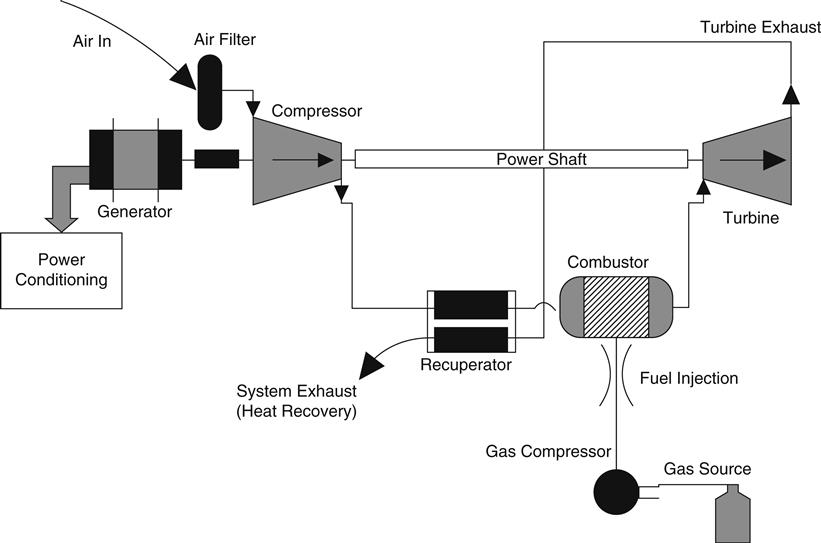
While some early product introductions have featured unrecuperated designs, the bulk of developers’ efforts are focused on recuperated systems. The recuperator recovers heat from the exhaust gas in order to boost the temperature of the air stream supplied to the combustor. Further exhaust heat recovery can be used in a cogeneration configuration. Figure 16–1 illustrates a recuperated microturbine system.
Fuel Cells
We now look at the basics of fuel cell technology, specifically solid oxide fuel cell (SOFC) technology.
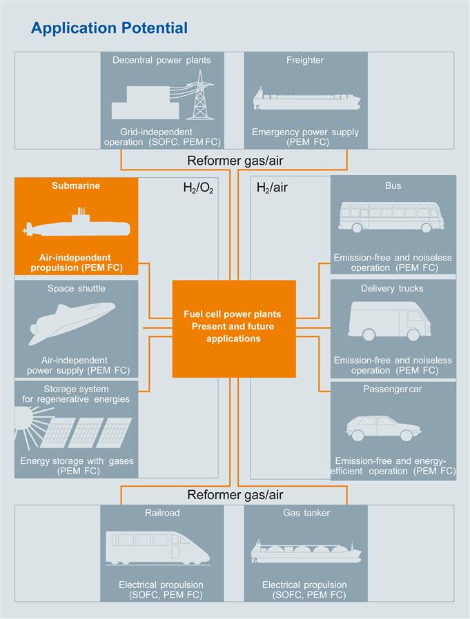
Many3 gas turbine OEMs now have divisions refining microturbines, fuel cells (SOFC or otherwise), and hybrids. We will look at Siemens SOFC design. Siemens Power Generation developed tubular SOFC technology with the support of the US Department of Energy’s advanced fuel cell research program and the German Ministry of Economics and Labor (BMWA). More recently, Siemens have used PEM (polymer electrolyte membrane) type fuel cells in naval submarines. The following figure points out applications for both the PEM and the SOFC basic designs (Figures 16–2 to 16–5).
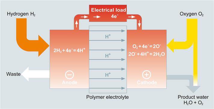
The PEM-type design4 turns on and off quickly, has low voltage degradation characteritics, a low operating temperature (80°C), can be overloaded and has no liquid corrosive electrolyte. The basic operation and components are simple, as illustrated in the next three figures.
Power Generation Tubular SOFC Technology
Siemens Power Generation’s Stationary Fuel Cells (SFC) division makes an SOFC type design. The Siemens Power Generation solid oxide fuel cell is made up of an electrolyte and two electrode layers in a unique tubular design. This design eliminates the need for seals required by other types of fuel cells, and also allows for thermal expansion. In a tubular SOFC design, air flows through the interior of the cell, and fuel flows on the outside of the cell. At elevated temperatures, the oxygen in the air ionizes and the resulting ions flow through the electrolyte and combine with the fuel on the cell’s exterior. This is an electrochemical reaction, so electrons are released. With proper connections, they can flow through an external circuit as electricity.
The design of the stack is simple. It is cooled using process air, and during normal operation consumes no external water. It also has integrated thermally and hydraulically within its structure a natural gas reformer that produces the hydrogen and carbon monoxide utilized by the cell. Also, except during startup, no external heat source is needed.
Siemens Power Generation’s first fuel cell product was the SFC-200 (Figure 16–6). This is a 125 kW SOFC cogeneration system, operating on natural gas at atmospheric pressure, with electrical efficiency of 44–47% at full load. An overall system energy efficiency of >80% is expected, assuming steam/hot water or other cogeneration.
Hybrids
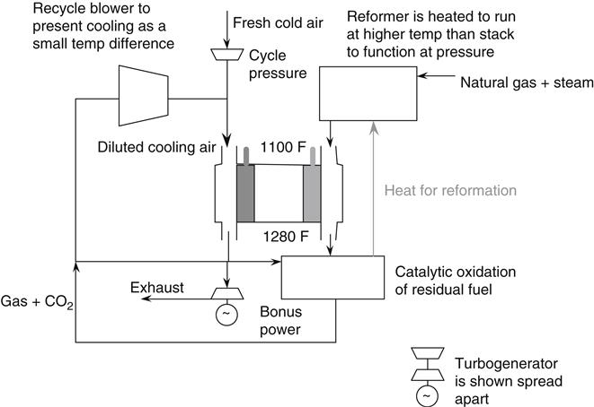
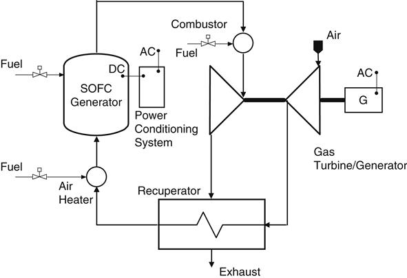
If an SOFC is pressurized, an increased voltage results, thus leading to improved performance. For example, operation at 3 atmospheres increases the power output by ∼10%. However, this improved performance alone may not justify the expense of pressurization, but what may is the ability to integrate the SOFC with a gas turbine, which needs a hot pressurized gas flow to operate. Since the SOFC stack operates at 1000°C it produces a high temperature exhaust gas. If operated at an elevated pressure, the exhaust becomes a hot pressurized gas flow that can be used to drive a turbine. If an SOFC is pressurized and integrated with a gas turbine, the pressurized air needed by the SOFC can be provided by the gas turbine’s compressor, the SOFC can act as the system combustor, and the exhaust from the SOFC can drive the compressor and a separate generator. This yields a dry (no steam) hybrid-cycle power system that promotes unprecedented electrical generation efficiency (Figure 16–7).
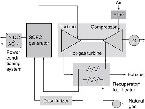
During normal operation of the pressurized SOFC hybrid, air enters the compressor and is compressed to –3 atmospheres. This compressed air passes through the recuperator where it is preheated and then enters the SOFC. Pressurized fuel from the fuel pump also enters the SOFC and the electrochemical reactions take place along the cells (Figure 16–8). The hot pressurized exhaust leaves the SOFC and goes directly to the expander section of the gas turbine, which drives both the compressor and the generator. The gases from the expander pass into the recuperator and then are exhausted. At –200°C the exhaust is hot enough to make hot water. Electric power is thus generated by the SOFC (dc) and the generator (ac) using the same fuel/air flow. Analysis indicates that with such SOFC/GT hybrids an electrical efficiency of 55% can be achieved at power plant capacities as low as 250 kW, and –60% as low as 1 MW using small gas turbines. At the 2–3 MW capacity level with larger, more sophisticated gas turbines, analysis indicates that electrical efficiencies of up to 70% are possible.
Future of SOFC/Gas Turbine Hybrids
Numerous alternative SOFC/GT hybrid configurations under a Cooperative Agreement with the US Department of Energy, National Energy Technology Laboratory have been studied. These studies have included hybrids with pressurized and atmospheric pressure fuel cell modules, turbines heated only by SOFC exhaust or also with supplemental duct heating and multiple, staged (cascaded) fuel cell/turbine reheat cycles. These studies have shown that while many different cycles offer considerable promise efficiency is maximized in a pressurized SOFC hybrid without supplemental firing, where the SOFC acts as the combustor for the gas turbine.
For large-scale applications (∼20 MWe) staged reheat cycles have indicated that electrical generating efficiencies could reach as high as ∼70%. These studies led to demonstrations of pressurized SOFC/GT hybrids in pursuit of these high electrical efficiencies. Through testing of a 220 kW and a 300 kW pressurized hybrid Siemens have verified the feasibility of the pressurized SOFC/GT hybrid concept. With these demonstrations Siemens have also demonstrated that the close-coupled pressurized hybrids are quite costly, but because of their feasibility and potential further development is warranted.
Studies of hybrid cycles indicated that atmospheric cycles, while offering somewhat lower efficiency than pressurized cycles, would be less complex to develop and quicker to implement. Because they would require less integration of the SOFC and gas turbine, they have the potential also to be less expensive and could accommodate a wider variety of gas turbines. Further study of other SOFC/gas turbine hybrid cycles is planned to assess their potential.
Further efforts are also needed on the part of government and industry to ensure the availability of appropriately sized small gas turbines. For pressurized hybrids especially, suitable mass flow, pressure ratio, and other characteristics are necessary.
Applications and Case Studies5
Grassroots design development is expensive and this field of small gas turbine systems providing distributed power lends itself to several OEM joint ventures and component supplier arrangements. Capstone turbine, for instance, uses a recuperator developed by Solar Turbines under the US DOE funding umbrella. Back in 2002, Ingersoll-Rand (IR) had formed an alliance with a division of Siemens to integrate the IR 70-kilowatt and 250-kilowatt PowerWorks microturbine products to create Microturbine Energy Systems. More recently, that division of IR has changed hands.6 IR’s microturbine technology functions as an on-site, micropower generation plant that can complement or supplement the user’s other sources of power. These systems utilize natural gas or other fossil fuels to produce small-scale electricity in the ranges of 70 kilowatts for a single unit, to 3 megawatts of capacity with multiple units. Exhaust heat from the microturbine can also be used to produce hot water or steam in a highly efficient combined heat and power (CHP) plant.
Case Study 1: Microbial Fuel Cells (MFC)
This work is still in developmental stages, but it is simple and promising.
Recent advances7 in MFC technology expanded the basic concept to production of fuels and chemicals such as hydrogen, methane, and ethanol, as well as using MFC for desalination.
MFC technology is gaining more attention as companies push for sustainability. However, there are many challenges to scaling these. Most designs have been tested only in the laboratory, and many tests are conducted in fed batch mode with synthetic wastewater. The viability of scaling up MFCs could open up new ways of generating renewable energy while treating wastewater, contributing to a more sustainable society.
How the MFC Works7
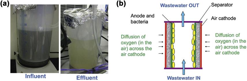
MFC is a bio-electrochemical system using micro-organisms on one or both electrode(s) to catalyze the oxidation or reduction reactions, and thus can be deployed for general water treatment applications. In the simple configuration depicted in Figure 16–9, the system could produce net electrical power.
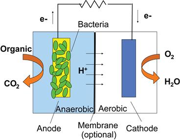
(Organics in wastewater) (O2 from the air)
Oxidation reaction at anode:
Glucose is oxidized by microorganisms, generating electrons and protons and ![]()
Reduction reaction at cathode:
Electrons and protons are consumed in the cathode compartment, combining with oxygen to form water.
Objective
To investigate the issues related to scale-up of MFC for wastewater treatment and explore practical applications.
Methodology
The performances of MFC under different test conditions were evaluated in terms of chemical oxygen demand (COD) removal efficiency, power generation and coulombic efficiency (CE). CE is defined as the percent of electrons recovered as current versus that in the starting organic matter.
Results and Discussion
Flow-through MFC showed a consistent power output throughout the operation while the power output of batch-mode MFC decreased with the depletion of COD in wastewater feed (Figure 16–10a–d).
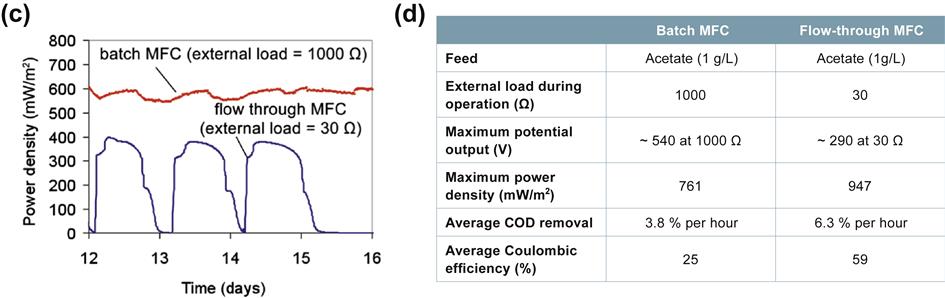
Performance of Scaled-Up MFC
Effect of Wastewater pH (Figure 16–11)
The COD removal efficiency decreased ∼10% as the pH fell below 7. The efficiency of power generation and CE were not affected significantly.

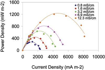
Effect of Wastewater Conductivity (Figure 16–12)
Power density increased significantly with increasing wastewater conductivity. The conductivity of wastewater did not affect the COD removal and CE.
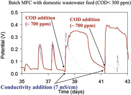
Effect of COD in Wastewater (Figure 16–13)
Spiking the domestic wastewater with acetate (∼700 ppm COD) immediately increased performance; whereas increasing conductivity (from 1 – 7 mS/cm) did not show significant improvement.
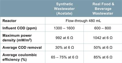
Synthetic versus Real Wastewater (Figure 16–14)
Real food and beverage wastewater performed similarly to synthetic wastewater.
Conclusions
Performance of up-scaled continuous mode MFC was comparable to that of small batch-mode MFC, confirming that the MFC design is scalable.
Performance of MFC was maintained when using real wastewater. Industrial wastewater with COD > 500 ppm is suitable for MFC technology.
Development of pilot scale MFC with real industrial wastewater is under way.
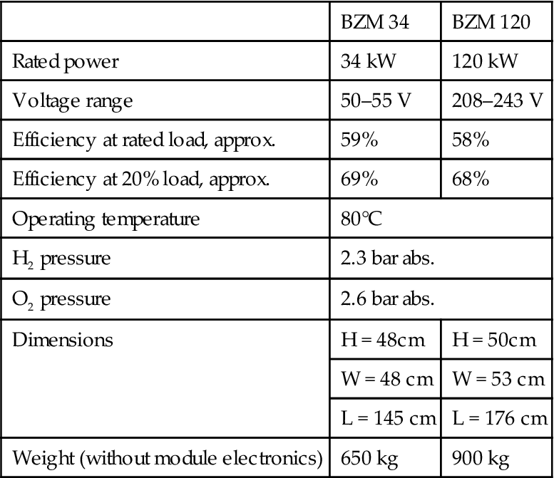
Case Study 2: PEM Fuel Cells (FCs) on Naval Submarines8
Figures illustrating voltage degradation, module output versus load current and efficiency for the two models Siemens makes (34 kW and 120 kW, respectively) and installs on submarines, follow (Figures 16–3, 16–4, and 16–5).
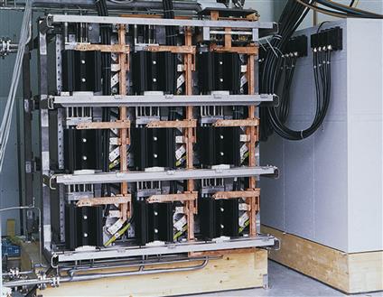
The following figures illustrate the peripheral systems (in Siemens application cases on naval submarines discussed earlier) with which the PEM FCs interface and a bank of FCs in a rack (Figures 16–15 and 16–16).
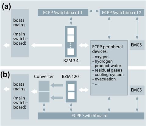
The data table (Table 16–2) on the two PEM fuel cells does not point out one important feature of the fuel cells in submarine application: they are noiseless.9
TABLE 16–2
Technical Data8
| BZM 34 | BZM 120 | |
| Rated power | 34 kW | 120 kW |
| Voltage range | 50–55 V | 208–243 V |
| Efficiency at rated load, approx. | 59% | 58% |
| Efficiency at 20% load, approx. | 69% | 68% |
| Operating temperature | 80°C | |
| H2 pressure | 2.3 bar abs. | |
| O2 pressure | 2.6 bar abs. | |
| Dimensions | H = 48cm | H = 50cm |
| W = 48 cm | W = 53 cm | |
| L = 145 cm | L = 176 cm | |
| Weight (without module electronics) | 650 kg | 900 kg |
Case Study 3: Microturbine in a CHP Application10
A CHP application example (Oregon) follows. In 2004, Siemens contracted to design, build, operate, and maintain a Combined Heat and Power Plant (CHP) to serve Oregon Health and Science University’s (OHSU) new River Campus in Portland, Oregon.
The CHP provides OHSU with a clean, flexible, reliable and efficient source of heat and electric power. It features five natural gas-fired microturbines, which produce all of the heat required by the facility, as well as 34% of its electric power.
The CHP serves Building One, a 400,000 square-foot facility that houses medical offices, outpatient surgery, research laboratories, a wellness center, an imaging center, conference center, retail outlets, and parking. It is the first building being built in the university’s expansion along the Willamette River in the new South Waterfront District.
According to the US Department of Energy, a CHP design will reduce the amount of fuel consumed by almost 40% when compared to a traditional fossil fuel-fired utility power plant and customer-owned boilers. In addition, OHSU estimates that CHP will reduce its CO2 emissions by roughly 9 million pounds per year.
A chilled water production plant will serve the cooling needs of the building. Both the CHP and chilled-water plants will be integrated and controlled as a coordinated central utility plant.
OHSU and its design and construction team are utilizing the US Green Building Council’s LEED (Leadership in Energy and Environmental Design) rating system to gauge the sustainability of the project. OHSU’s goal is to achieve a gold LEED rating. Innovative features of the new OHSU facility, such as using rainwater to flush public fixtures and a internal bioremediator to treat waste, might just earn it LEED’s highest platinum rating.
Siemens is helping OHSU to secure financial incentives for the CHP. State tax credits from the Oregon Department of Energy, combined with financial incentives from an Energy Trust of Oregon pilot project, contribute to making the project an effective choice for OHSU.
Case Study 4: A Fuel Cell Application11
The target this DOE-sponsored partnership’s effort (Rolls Royce Allison and stack manufacturer) was aimed at producing between 3 and 30 MW units at under $1500/kW uninstalled. Interim progress is discussed. Work in this field continues.
Rolls Royce is working with a molten carbonate fuel cell manufacturer to accelerate commercialization of a pressurized power generation package. The intent of the participants is to introduce stack and reformer improvements coupled with a new system integration approach to achieve a product with commercially competitive qualities. Cost-effectiveness and durability must be brought to fuel cell systems that already achieve high efficiency and low emissions.
A key element of the program will be endurance testing in base load mode for extended periods. Stack performance will be tracked in order to assess the maximum useful working life of this high investment component.
Load following generally requires careful management in fuel cell systems, typically because the stack/reformer system should be kept in a near-steady state environment. This will be demonstrated.
Existing systems have usually been designed somewhat similarly to a chemical process plant, using off-the-shelf components. This approach leads to a highly predictable but excessively complex and costly system. System simplification and cost reduction efforts have been initiated, with a goal of a 3:1 reduction in the cost of the balance-of-plant.
Preliminary results of this work are not available due to a delay in the start of the program. The cost reduction goal is to bring the plant uninstalled cost to less than $1500/kW. The projected costs of early commercial systems as currently estimated are almost twice this goal.
Project Description
The baseline system to be tested in the evaluation program for performance and durability consists of three distinct modules: the power module, the mechanical module, and the electrical module. This is the configuration selected for most exploratory fuel cell plants. The primary purpose of this first system is to demonstrate stack life, performance, and operational characteristics of the new stack and reformer. The prototype system test bed configuration represents a more flexible but more expensive system than that required for a commercial product.
A simplified schematic of the pressurized molten carbonate fuel cell (MCFC) test system is presented in Figure 16–17. The power module contains the fuel cell stack assembly, reformer, manifolds, and the anode (fuel side) recirculation ejector. The mechanical module includes all other major air and fuel gas management equipment including the turbo-machinery, gas desulfurization system, cathode recycle blower, valves, and interconnect piping. The third module, the electrical module, provides power conditioning, electronics, and system controls.
High Temperature Fuel Cell Plants
The three fuel cell systems studied by Rolls Royce Allison under the DOE High Efficiency Fossil Power Plants (HEFPP) conceptualization program have the following major components in common:
In pressurized systems, the fuel cells act in place of a combustor for the turbogenerator. In the unpressurized system, the fuel cell is placed in the turbogenerator exhaust stream but also supplies heat and residual fuel to a heat exchanger acting as an indirect combustor.
Additional major components for individual systems are:
Though each system has distinctive merits and challenges, a common problem is that each module is of high cost.
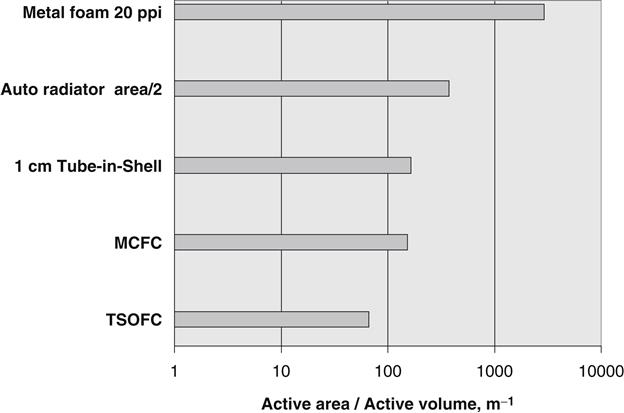
The power module uses raw materials that are expensive and heavy, whether they are ceramic or nickel based. At present, each kilowatt requires 10–20 lbs. of active fuel cell and 10–20 lbs. of associated structure, or more than 15 tons of stack per megawatt. This ratio is considerably higher than for a simple cycle gas. The fuel cell active surfaces can provide a range of current density in which the delivered voltage (efficiency) drops as current rises but there is little scope for increasing the current per unit area at the high efficiency. It follows that the required route is to increase the active surface area in a given stack volume, a requirement very similar to that of producing compact high effectiveness heat exchangers. Figure 16–18 gives an indication of the comparative compactness of available fuel cells and heat exchangers.
Stack pressurization is required in order to provide enough fuel and oxidizer gas to these compact active surfaces with low parasitic pumping loss. This is the primary reason for the belief that pressurized systems are the long-term valid solution. Though more heat is released per unit volume of stack, it is carried away by proportionally more gas, thus avoiding excessive temperature. Pressurization also offers important secondary gains, both increasing the power that may be drawn at a given level of stack efficiency and making it easier to convert cycle heat into electricity in associated turbomachinery (accounting for 10–20% of total system power), without using more fuel.
A preliminary comparison of performance characteristics and rough order of magnitude cost of solid oxide and molten carbonate systems was conducted. The results indicate that near term (before 2010), the two offer a similar level of performance and technical challenges. The somewhat simpler system advantage of the solid oxide is offset by its often higher operating temperature. The lower cost of the balance-of-plant system for the SOFC tends to be offset by higher stack cost.
The MCFC system’s pressurized reformer has to be supplied with an excess of steam in order to suppress carbon formation. This phenomenon poses a significant complication, and requires the continuous addition of treated water to the cycle.
The higher operating temperature capability and the flexibility provided by a planar solid oxide stack arrangement indicates that the solid oxide system will dominate in the longer term. Over the long term, the SOFC stack offers the following potential advantages:
An opportunity has been made available to partner with M-C Power in the pressurized MCFC programs. This opportunity represents the earliest possibility to launch a fuel cell hybrid product. Pressurized MCFC and SOFC systems will enable moving towards longer-term aspirations of launching higher power density products. The intent is to introduce into operation the first in-service pressurized MCFC system. The plan is to participate in designing and developing the prototype systems, currently funded by the DOE MCFC Product Design and Improvement (PDI) program.
Pressurized MCFC System Design
M-C Power gained considerable insight into the design and functioning of pressurized MCFC systems. This valuable experience was gained by running the plant installed at the Miramar Naval Air Station (test units ranging in size from 75–250 kW). This system is not a full hybrid. Although turbomachinery is used to turbocharge the system to about 3 atmospheres, no attempt is made to generate bonus electrical power with it.
A plant design for the PDI program was developed by the M-C Power partnership based on the operating experience gained at the Miramar station. The PDI program incorporates a number of improvements:
• Power increased to 450 kW (improved stack mechanical and thermal design, and materials modifications)
• Temperature stable reformer/catalytic combustor
• Turbogenerator used for about 10% power bonus
The proposed PDI system analysis made it apparent that the cost of the system was very high as designed. The first reaction is, of course, that the stack and reformer are determined to be expensive because they are complex parts produced on a “once-off handmade” basis. This was expected. There is a coherent plan to decrease their cost by an order of magnitude. The electrical module cost was based on off-shelf power conditioning and power electronics components. The cost of this module represented a minor portion of the overall system cost. This is partly because good electronic control systems are very competitively priced and inverters are continuing to decrease in cost.
What came as a surprise, however, was that the collection of pipes and valves in the mechanical module, specified to service the system, is the major cost challenge. Unlike the stack and reformer, the mechanical module is an assembly of standard, volume produced, components that are not likely to reduce cost. The PDI plant is configured in a fairly straightforward “chemical plant” style, with pipe work and valves linking and controlling the major processes. The mechanical module assembly, manufactured as prototypes with soft tools and jigs, requires a large number of pipes and valves. The components of the mechanical module alone cost more than the intended early production cost of the whole plant. This high system cost problem is being attacked to resolve it by a different approach. The plan is to modify the overall system operational control, and greatly simplify system integration. The following integration changes have been proposed:
• Put all critical pipe connections inside the pressure vessel that houses the stack and reformer.
• Air delivered from the intake compressor is discharged into the pressure vessel.
• Turbine is driven by the exhaust gases as they emanate and then pass to the external exhaust heat recovery unit.
• All other flow manipulation is accomplished inside the pressure vessel, and can therefore be handled in lightweight ducts (with small pressure differences across the ducts).
• Small leaks are acceptable and this opens the way to using slip joints if necessary.
• Eliminate motorized air/gas valves. Select and use the turbomachinery and its electrical loading to master flow control, probably aided by a waste gate system.
• Provide an integrated turbomachinery package. Replace the present large low speed industrial hot recycle blower and its variable frequency drive and drive motor by a small high speed fan. The fan is driven by a free power turbine using the same hot gas stream as the turbogenerator turbine.
The resulting system package, which is closely integrated, is sketched in Figure 16–19.
Revised system cost estimates indicate that these changes decrease the total initial production plant cost (uninstalled) by 30% and the long-term plant cost by 45%.
Wide Application Fuel Cell Turbomachinery12
The DOE is urging the development of high efficiency hybrid fuel cell/gas turbine systems generating electric power in the range of 20–30 MW. The long-range plan is to enable these systems to serve the 21st century power generation needs in the US and globally. Fuel cell manufacturers, working on the High Efficiency Fossil Power Plant (HEFPP) program, examined a variety of fuel cell cycle arrangements reaching the level of efficiency specified. From this work, it is possible to draw a number of conclusions:
1. The attainment of 70% efficiency is challenging yet attainable, requiring improvement in stack efficiency, fuel utilization, and supporting system efficiency.
2. Turbomachinery is mostly configured as though for a recuperated cycle (compressor discharge flow supplied to stack and returned to turbine) with generator.
3. The required pressure ratio may be less than that available in high-pressure ratio gas turbines.
4. Cycles may require intercooled compressors.
5. Supporting machinery flow size is relatively low, usually less than 50 lbs./sec of air being required for a 20 MW hybrid system.
6. Each stack module power output is much less than 20 MW, so plant may divide the total flow between multiple small turbines, perhaps 5 lbs./sec each, depending on modular concept selected. Suitable gas turbines are not available at this size.
7. Approximately 40,000 hours of base load operation poses a major challenge to small turbomachinery. To achieve this life, special bearings may be needed.
8. Turbine entry conditions are mostly limited by stack capability below level demanding blade cooling.
What emerges from these preliminary system definitions above is the need for a turbogenerator with a minimum specification quite close to that of a “fuel cell flexible” (FCF) turbine. These turbines will be designed to a pressure ratio of 4–8, turbine temperature of 1700°F, recuperated and fitted with a generator. The flow size of emerging microturbines is limited to about 2 lbs./sec, but larger versions may follow. Using FCF turbines offers a big cost benefit because they are to be mass produced.
Currently available microturbines fall short of the pressure ratio and mass flows indicated for maximum efficiency pressurized fuel cell systems. An optimum pressure ratio of 7 appears to be suitable for both SOFC and MCFC systems. This is a coincidental outcome, because the cycles are different due to diverse characteristics of active components of the molten carbonate and solid oxide fuel cells.
Therefore, there is the possibility that a dedicated style of gas turbine should be developed, which could serve several types of fuel cell systems. Its specification is likely to be:
| Pressure ratio | 7 |
| Turbine entry temp | 1700°F max |
| Flow size | 5–20 lbs./s |
| Stall margin | Generous |
| Combustor | Start only |
| Compressor | One-stage radial |
| Intercooler | None |
| Ducting | As if recuperated |
| Turbine | Two-stage axial |
| Bearings | Non-contact |
| Adaptability | Scalable |
This unit has the potential to serve as a high efficiency small turbogenerator if recuperated. By combining fuel cell and stand-alone turbogenerator market opportunities, it may be possible to provide a generous return on the initial investment, and minimize the fuel cell system cost.
A schematic indicating the configuration of this gas turbine is presented in Figure 16–20. The design proposed in this figure represents an approach of a fuel cell flexible or fuel cell neutral turbomachinery.
The design approach represented for hybrid fuel cell systems is usually analogous to gasification systems and pressurized fluidized bed combustion systems. These approaches have tended to lead to expensive system configurations.
At the bench-top level of fuel cell experiments, it was naturally convenient to use readily available components to build the pressurized systems. For pressurization, the most convenient source of mildly compressed air is a radial compressor driven by a synchronous electric motor. This type of pressurization requires no direct control of the overall system because the user can add motorized valves to select pressures and flows as required.
Incorporating a fuel cell flexible gas turbine that is specifically designed to serve the needs of pressurized fuel cell systems would enable achieving these key benefits:
• A fuel cell flexible gas turbine would help simplify operational control by minimizing high temperature ducting and a vast number of valves.
• A fuel cell flexible gas turbine would also enhance operational stability of a fuel cell hybrid by controlling the generator loading, therefore spool speed in a single shaft machine.
• It would also help improve the system load following capability.
• The turbine would help minimize the fuel cell stack pressure and temperature fluctuations, by maintaining mass flow uniformity, resulting in uniform pressure and temperature distributions within the stack.
• The operational stability of the fuel cell stack (facilitated by the FCF gas turbine) is necessary to achieve hybrid system life in the range of 40,000 hours under steady state base load operating conditions.
• A gas turbine designed specifically to be compatible with fuel cell operating requirements would facilitate overall design simplification.
• With system design simplification, both in the mechanical module and the power module, it would be easier to meet the system cost reduction goal specified earlier.
• A FCF gas turbine would serve the needs of the various high temperature pressurized hybrid systems. Meeting this goal is important in order to reduce the cost of turbomachinery, since these are likely to be produced initially in comparatively small quantities.
• A FCF turbine would impact favorably the cost of the mechanical module.
• Another important potential benefit of having a gas turbine designed specifically for fuel cells is the ability to ensure power quality of the system due to the fact that the entire system would have a tendency to operate with great stability. An operationally stable fuel cell hybrid system would allow the meeting high power quality requirements on a sustained basis.
• A pressurized fuel cell hybrid system utilizing a performance optimized compatible gas turbine would derive other benefits such as the system’s ability to simplify the grid interconnect.
• The system would be able to access grid interconnect directly to an AC power line. The Institute of Electronics and Electrical Engineers (IEEE) is developing an interconnect standards under the 519 code. It would be possible to couple the system to the grid through a properly designed gas turbine and a correspondingly compatible electrical module. Such an approach would eliminate use of a DC load bank and a more complicated grid interconnect.
• The system incorporating several of the cost reduction techniques would also have the capability to serve in the combined heat and power (CHP) mode.
• It is necessary for these distributed resources systems to offer not only the electrical output, but also heat and cogeneration capability.
The ultimate objective of the cost reduction and design simplification program is to reduce stack cost by at least 40%, and overall system cost by approximately 45%. These numbers represent the type of cost reduction from current levels required to achieve system costs of <$1500/kW (uninstalled). Preliminary economics evaluations indicate that at the target costs, fuel cell hybrid systems will be competitive on the basis of cost of electricity with competing energy sources.
Case Study 5: Tubular Solid Oxide Fuel Cell/Gas Turbine Hybrid Cycle Power Systems13
This case involved a partnership between Siemens Westinghouse and SOFC Power Generation. Funding was provided by the US DOE, Ontario Hydro Technologies and their Canadian funding partners, and the Institute for Advanced Energy of Japan.
A pressurized SOFC/GT hybrid cycle power system is depicted schematically simplified in Figure 16–21.
The SOFC generator is pressurized, operating on recuperatively heated process air supplied by the compressor. The power system based upon this cycle achieves increased power output and higher efficiencies due to the utilization by the gas turbine generator of thermal energy in the pressurized SOFC exhaust stream. Power system performance is also enhanced by SOFC generator operation at elevated pressure. For a given cell operating current, cell voltage, cell power output, and efficiency increase logarithmically with pressure. The gas turbine combustor and the air heater are fired during system startup operations, and they could be fired during peak-power or turndown periods. For maximum system efficiency during steady-state operation at system rating, neither combustor is fired.
A recent study concluded that high cycle efficiencies are achieved by directly expanding SOFC exhaust gas at the gas turbine without firing supplemental fuel at the GT combustor, highlighting the synergy of SOFC and gas turbine integration. The projected performance of small-capacity SOFC/GT hybrid power systems based on specific small gas turbines is discussed. In addition, performance estimates for the first constructed SOFC/GT hybrid power system are provided.
Siemens Westinghouse Program Status
Focus has been on the operation of a 100 kWe atmospheric-pressure SOFC-CHP demonstration power system in the Netherlands, and on the design and fabrication of a 220 kWe PSOFC/GT hybrid cycle power system. The 100 kWe system, sponsored by EDB/ELSAM, a consortium of Dutch and Danish energy generating and distribution companies, is installed on a utility site near Arnhem, and has logged over 6000 operating hours. It generates approximately 110 kWe net AC power at 46% efficiency (net AC/LHV) for the utility grid, and hot water for the local district heating system. The demonstrated energy efficiency is nearly 75%.
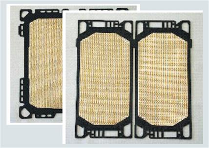
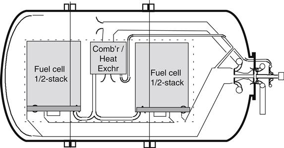
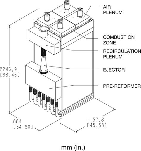
The SOFC generator for this system uses a stack of 1152 tubular cells, each cell having a diameter of 22 mm and an active length of 1500 mm. The cell stack can be viewed as composed of two 576-cell substacks, each having its own ejector, ducting, and reformer assembly for the recirculation of moisture-containing depleted fuel and the reformation of incoming fresh fuel, and a zone above the cells for the combustion of electrochemically-unreacted fuel. A substack, pictured in Figure 16–22, is the building block for the SOFC generators to be discussed later.
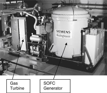
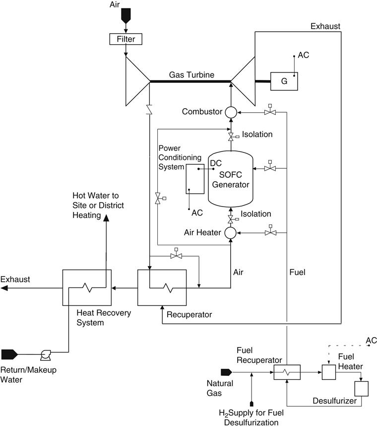
The 220 kWe PSOFC/GT hybrid cycle power system, the world’s first such hybrid and is sponsored by Southern California Edison (SCE), was designed and built by Siemens Westinghouse, and is scheduled for installation and operation at the University of California, Irvine, in early 2000. It is a proof-of-concept system, and a major objective of the program is to demonstrate the integration of the SOFC and gas turbine technologies, and hybrid system operation. The system is based on the cycle depicted in Figure 16–23.
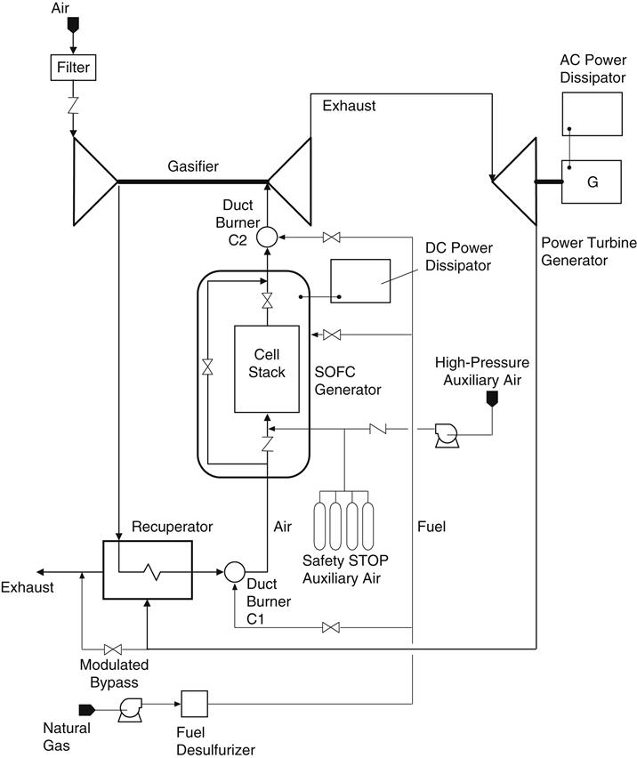
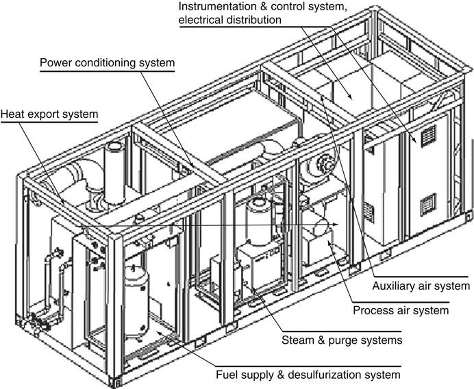
The gas turbine, a recuperated, two-shaft machine, was supplied by Northern Research and Engineering Company (NREC), a division of Ingersoll-Rand. The engine is a modified version of the 75 kW gas turbine that NREC is developing and commercializing for power generation, mechanical drive, and CHP applications. Figure 16–24 provides a pictorial view of the skid-mounted hybrid cycle power system. Approximate overall dimensions for the system are 7.4 m (l), 2.8 m (d), and 3.9 m (h). The SOFC generator consists of a cell stack that is housed in the vertical cylindrical pressure vessel. The stack in this particular power system is composed of two 576-cell substacks, and is of the design used in the 100 kWe atmospheric-pressure SOFC-CHP system. No significant modifications were needed to adapt the stack design for pressurized operation. The gas turbine receives hot SOFC exhaust at the gas turbine combustor inlet, and it sends recuperatively-heated process air to the SOFC generator inlet. The hot gas is expanded partially across the gasifier turbine, which rotates at approximately 70,000 rpm, and drives the compressor. The expansion of the hot gas is completed across the power turbine, where the derived shaft power turns the generator. A typical power turbine shaft speed is 44,000 rpm. Initially, the electric power produced by both the gas turbine and the SOFC generator will be dissipated.
As indicated in Figure 16–23, the SOFC generator is valved to permit the flow of air around the cell stack. The gas turbine can therefore be started before the SOFC generator, by firing the gas turbine combustor, and air can be directed around and through the SOFC generator in desired proportions.
With the gas turbine started, exhaust heat recovered at the recuperator is available to aid the SOFC heat-up process. The air heater is fired during this process, but the flow of fuel to the heater and to the GT combustor are turned back to zero as steady-state operation at the peak-efficiency rating point is achieved.
Power system performance estimates are presented in Table 16–3. For these estimates the efficiency is calculated assuming all power is exported to the AC grid, and reasonable power conditioning and turbine generator efficiencies are applied.
TABLE 16–3
220 kWe PSOFC/GT Power System Performance Estimates [16-6]
| Cell current | 250 amps |
| Cell voltage | 0.610 V |
| Compressor pressure ratio | 2.9:1 |
| Air intake rate | 0.58 kg/s |
| Turbine inlet temperature | 780°C |
| SOFC DC power | 187 kW |
| SOFC gross AC power | 176 kW |
| Gas turbine AC power | 47 kW |
| System net AC power | 217 kW |
| Efficiency (net AC/LHV) | 57% |
Commercial Product Design Studies
Based upon market study, the conclusion is that PSOFC/GT hybrid cycle power systems will have competitive advantage, due to their high efficiency and low installed cost, in the distributed generation market in the 200 kWe to 10 MWe capacity range. To begin defining potential products in this range, conceptual design studies have been undertaken to project system configuration and appearance, and to estimate performance and cost. Aspects of two studies are discussed. In one, the Allied-Signal Parallon 75 turbogenerator was specified, and the SOFC generator was sized to match the turbine. The result is a power system concept that would be rated at approximately 300 kWe, with an efficiency of 57%.
The objective of the second study was to conceptualize a hybrid power system with rating of at least 1 MWe. Gas turbines under development by Solar Turbines and NREC could be deployed in the system concept that resulted, and a net AC efficiency of near 60% is projected. The performance estimates presented herein for both power systems are pre-commercial values, which are expected to be achieved in demonstration systems. Higher power outputs and efficiencies are projected for the mature-product SOFC technology, which will be available by 2010 or sooner.
300 kWe-Class Hybrid Power System
The cycle for this system is depicted in Figure 16–25. It is shown in CHP mode, with a heater for the preparation of hot water for site or district using heat recovered from the system exhaust. The Allied-Signal turbogenerator is a single-shaft recuperated gas turbine that powers a high-speed, direct-drive alternator. An important function of the turbine is to supply a steady flow of air to the SOFC generator. The ability to modulate the GT electric load to maintain shaft speed at set point, and the ability of the turbine to operate across a range of turbine inlet temperatures, enables steady air flow over a range of flows, an important consideration for SOFC thermal management.
The SOFC generator was sized to match the turbine flow characteristics, assuming no firing of the gas turbine combustor. The resulting cell stack, consisting of three 576-cell substacks, is best arranged in a horizontal monolithic configuration, which in turn is well suited for installation in a horizontal cylindrical pressure vessel. A system pictorial view is presented in Figure 16–26. It is envisioned that the power system would be factory-assembled on a single truck transporter. The skid would then be jacked into place at the installation site, or the transporter could be designed with a removable wheel and axle assembly, and the bed containing the system would simply be left at the site. System performance estimates are provided in Table 16–4.
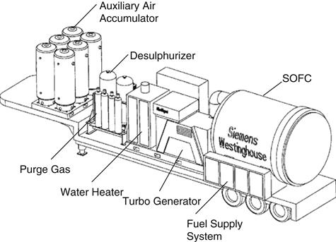
TABLE 16–4
300 kWe-Class PSOFC/GT-CHP System Performance Estimates (Pre-Commercial) [16-6]
| Cell current | 250 amps |
| Cell voltage | 0.635 V |
| Compressor pressure ratio | 3.5:1 |
| Air intake rate | 0.64 kg/s |
| Turbine inlet temperature | 1145 K |
| Combustor and air heater fuel flow rate | 0 |
| SOFC DC power | 270 kW |
| SOFC gross AC power | 251 kW |
| Gas turbine AC power | 67 kW |
| System net AC power | 307 kW |
| Efficiency (net AC/LHV) | 57% |
| Gas temperature at water heater inlet | 477 K |
| Hot-water heat recovery rate | 95 kWt |
| Hot-water temperature | 393 K |
| Hot-water flow rate | 0.3 kg/s |
| Heat recovery efficiency (kWt/LHV) | 18% |
| Energy efficiency [(net AC + kWt)/LHV] | 75% |
| Exhaust flue temperature | 330 K |
MWe-Class Hybrid Power System
The simplified cycle diagram for a MWe-class PSOFC/GT power system is presented in Figure 16–27. It is similar to that for the 300 kWe system, with the exception that the MWe-class studies did not consider hot water heat recovery. As in the 300 kWe-class system, the gas turbine is a recuperated, single-shaft machine, with the alternator load modulated to control shaft speed and air flow to the SOFC generator.
The SOFC generator for this system uses 10 576-cell substacks in a horizontal pressure vessel. The power system is configured as two factory-assembled skids; the SOFC and gas turbine equipment is installed on one skid, and balance-of-plant hardware is installed on the second skid. Each skid will be transported to the installation site in a single truck shipment. At the site, trailer wheel assemblies are removed, and the transporter skids are lowered into place on prepared pads. Other installation activity at the site will involve, in addition to the site preparation work, the interconnection of the skids, and the completion of the system/site interfaces. Performance estimates for the MWe-class power system are presented in Table 16–5. For these particular estimates the gas turbine was modeled using information on a developmental 300 kW Solar Turbines engine.
TABLE 16–5
MWe-Class PSOFC/GT Power System Performance Estimates (Pre-Commercial) [16-6]
| Cell current | 239 amps |
| Cell voltage | 0.643 V |
| Compressor pressure ratio | 3.3:1 |
| Air intake rate | 2.0 kg/s |
| Turbine inlet temperature | 1144 K |
| Combustor and air heater fuel flow rate | 0 |
| SOFC DC power | 879 kWe |
| SOFC gross AC power | 818 kWe |
| Gas turbine AC power | 218 kWe |
| System net AC power | 1014 kWe |
| Efficiency (net AC/LHV) | 59% |
| Exhaust flue temperature | 515 K |
Case Study 6: A Turbogenerator for a Fuel Cell/Gas Turbine Hybrid Power Plant14
This work was also funded by the US DOE. When Rolls Royce merged with Allison, its gas turbine range then included very small gas turbines that powered helicopters. Fuel cell manufacturers have been concerned that the small gas turbines that are available are not reliable enough to power commercially viable hybrid systems. So DOE is sponsoring the development of turbogenerators for use with hybrids.
Special Purpose Gas Turbine for Fuel Cells
Stack designs have to simultaneously achieve good fuel and air distribution, uniform heat dispersal, minimized thermal gradients in stacks, comply with mechanical and thermal stress limitations, and provide consistent cell to cell electrical continuity. In several cases, these features are achieved in two adjacent types of zone, the reforming zone and the active cell zone. The complexity of meeting these requirements increases with stack power level. Currently, the three major “full-size” technologies, solid oxide, molten carbonate, and direct (molten carbonate), have all been limited to a maximum single stack assembly power level of about 0.3 MW. An installation of such low power level would inevitably result in very high plant capital cost per unit power. Manufacturers, realizing a limited market potential for such units, have proceeded to build multi-stack plants. A 1 MW hybrid is often seen as the smallest plant size likely to have substantial cost competitive, environmental and commercial appeal.
It is prudent to ship fuel cell systems largely assembled and this implies limiting module dimensions to those that can be trucked economically, i.e., as indicated for 1–2 MW hybrids. Design proposals by three manufacturers for very high efficiency 20 MW plant, arising from feasibility studies funded by the US Department of Energy, concluded that these systems would be based on multiples of the same stack modules. Large plant systems were evaluated under a DOE High Efficiency Fuel Cell Power Plant feasibility study program in 1999–2000. This program showed that fuel cell plant efficiency can be raised from about 55% to >70%.
A relatively simple, low-cost turbogenerator will be the best option for fuel cell plant of up to approximately 10 MW hybrid capacity, supporting efficiencies >65%. The same gas turbine can serve as the core of a larger capacity turbogenerator for up to a 30 MW fuel cell plant.
The turbogenerator to be designed on this project will be matched initially to serve the needs of a 1–3 MW hybrid plant. The unit will combine the following features:
A stand-alone gas turbine will also result as an important by-product of this design. By using recuperation and appropriate ceramic components, this stand-alone gas turbine could achieve 40% thermal efficiency.
Turbogenerator Operating Characteristics
The initial mass flow and pressure ratio requirements are based on the latest concepts of the fuel cell manufacturers for their hybrid systems. Some fuel cells start with larger flow requirements, both the solid oxide and molten carbonate fuel cells need 1 kg/sec/MW generated. Stack unit power is a consistent factor.
Four major hybrid configurations are presented in Table 16–6. The data given are representative and will be reviewed with the fuel cell manufacturers to confirm their latest standards. The last cycle shown in Table 16–6 represents a more complex higher efficiency solid oxide system that requires a minimum of one module-pair (stacks operating in two different pressure zones).
TABLE 16–6
Preliminary Cycle Parameters (Fuel Cell/Gas Turbine Hybrids) [16-7]
| Cell Type | Cycle | Total Power, MW | Turbine Press, Bar | Stack T in, °C | Stack T out, °C | Total Airflow, Kg/s | Plant Efficiency, % |
| Solid oxide | Pressurized stack, recuperated | 1.3 | 4–6 | 600 | 870 | 2 | 60 |
| Molten carbonate | Atmospheric stack, recuperated | 3.1 | 9 | 580 | 660 | 2.8 | 65 |
| Molten carbonate | Pressurized stack, recirculated | 2.1 | 8 | 590 | 690 | 2.5 | 65 |
| Solid oxide | Series modules, pressurized and recuperated | 2.5 2nd 3 |
1st >6700 | 600 and | 870 | 2.3 | 65 |
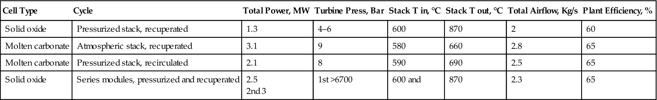
1. Baseline solid oxide hybrid system. Pressurized stack. Heat recovery by recuperation.
2. Molten carbonate hybrid system. Pressurized stack. Heat recovery by recirculation.
3. Molten carbonate hybrid system. Ambient pressure stack. Heat recovery by recuperation plus indirect residual fuel combustion.
4. Alternate solid oxide hybrid system with series modules. Pressurized stack. Recuperated.
The solid oxide ambient pressure hybrid was not included in this assessment, because the system becomes economically unattractive in MW class range. Such a system would require a very high temperature recuperator. To date, fuel cell manufacturers have expressed limited interest in a SOFC ambient pressure hybrid system.
The table contains the total airflow required for the various types of fuel cells, which is roughly the same for each system. Even more significant is that the higher flow requirements are also compatible with higher operating pressure ratio. This tabulation supports the notion that a properly designed single turbogenerator would satisfy all the high temperature fuel cell systems. The last cycle configuration points out that turbine reheat may be needed for this hybrid system. Using this preliminary data, a turbogenerator is being configured to provide 2.8 kg/s airflow, work at a pressure ratio of 9 and accept 1000°C at turbine entry. Such a turbogenerator would serve all systems. It would be operated at part speed to lower its pressure ratio for the solid oxide systems. If used as a stand-alone module, the initial unit would develop <1 MW power.
Turbogenerator Design Parameters
Industrial gas turbines generating above 5 MW capacity have a maintenance-free life expectancy of 30,000 hours when operated at the lower temperatures required in fuel cell hybrid systems. This long life, however, is not achieved by small gas turbines. Gears and rotating element bearings are examples of components that have finite fatigue life associated with operating high speed, which results in Hertzian stresses. As power is proportional to length squared, a 200 kW machine theoretically would have about 1/5th the life of a 10 MW machine. This would suggest 40,000/5 = 8000 hours working life for a small gas turbine generator. This is consistent with experience.
The turbogenerator being designed on this project utilizes the following key components:
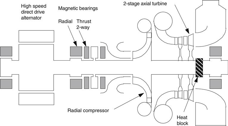
Active Magnetic Bearings
For the design being analyzed, it was decided to eliminate all gears and rotating element bearings. The company has extensive experience in the application of active magnetic bearings (AMB) in <100 kW units. Such a generator was designed, developed and tested in early 1990. This prototype performed successfully in automobiles as demonstration vehicles. The unit demonstrated great advantage of AMBs. Commercially available systems have inadequate sensing/control systems. These systems were completely redesigned in-house and gave very satisfactory results. Some 300 hours of engine running experience confirmed that the system was functionally fully effective.
Direct Drive Alternator
Parasitic losses normally become a major penalty as engine size decreases (presumably oil viscous shear stress increases because velocity differences remain the same but the clearances as a function of film thickness decrease). Conventional gears and bearings produce over 10% loss in a small machine compared to approximately 2% in a MW class machine.
A high-frequency direct drive alternator (DDA) is a necessity if gears are to be eliminated. Microturbine manufacturers have shown that DDA can be used effectively, but this class of generator is not a mature technology. Widely different designs are being developed and offered. The goal for this project is to achieve alternator efficiency >95%. The combination of AMB and DDA yields a turbogenerator that uses no oil. The DDA requires inverters to produce 50 or 60 Hz AC output. But this is a minor addition compared to the fuel cell requirements for larger inverters to convert their DC power to 50 or 60 Hz AC output.
Turbine Core Design
Previous cycle analysis showed that both atmospheric and pressurized MCFC cycles were fairly insensitive to the turbogenerator pressure ratio level selected. A range between 6 and 15 PR seems acceptable. The SOFC cycle as shown in Table 16–5 is more constrained in maximum pressure ratio by the requirement to heat the stack inlet flow by heat exchange with the turbine exhaust.
The determining parameters are the stack minimum inlet temperature and the turbine efficiency. With nominal stack and an efficient turbine, the maximum workable pressure ratio is approximately 4½. If the turbine efficiency were 5% worse, implying less heat removal, the acceptable pressure ratio would rise to 6. If the turbine remained efficient but the minimum acceptable stack inlet decreased 100°C (200°C has been indicated as a target), then the acceptable pressure ratio would rise to 8.
Selecting a turbogenerator design pressure ratio of 9 thus appears to provide immediate support to MCFC systems. This turbogenerator would also permit operation of early versions of standard SOFC hybrid plants at part speed and a pressure ratio of up to 6. This approach enables retention of the flexibility for likely development of SOFC stacks of higher temperatures. Maintaining high turbine high efficiency over the range 4½ to 9 pressure ratio would be accomplished by allowing a low cost compressor diffuser vane sets to be compatible with high or low PR applications.
The Model 250-C40 radial compressor provides a high efficiency basis for this machine at the correct flow size. Without the constraints of helicopter installation, the design can be adapted to still higher efficiency. A conservative maximum efficiency turbine for 9 pressure ratio would have three stages, but the high speed of the 250 impeller helps to enable a two stage version with reasonable loading and acceptable efficiency.
Stand-alone unrecuperated efficiency of this unit is approximately the same as typical existing 3 MW industrial gas turbines. It appears to have potential for similar, i.e., combined heat and power (CHP) applications. If recuperated, its efficiency becomes about 35%. This level is good enough to compete with some diesel engines and to serve in the distributed generation role without resorting to CHP or other energy recovery systems. The low operating temperature significantly reduces greenhouse gas emissions. This feature in combination with the elimination of oil makes this turbogenerator a very “green” and cost effective alternate to a diesel. With very long life expectancy, it also promises to be more suitable for base-load service than a diesel.
The combination of relatively high-pressure ratio and reduced parasitic losses helps to improve the potential of this unit as a stand-alone unit. Table 16–7 indicates the performance of the unit and its possible derivatives.
TABLE 16–7
Performance of the Proposed Turbogenerator and Derivatives [16-7]
| Configuration | Airflow, kg/s | Press. Ratio | Turbine Inlet, °C | Recup. Inlet, °C | Stack Temp., °C | Power, MW | Thermal Efficiency |
| Turbogenerator design pt | 2.80 | 9.00 | 900 | 474 | 0.476 | 0.253 | |
| Operation with PSOFC | 1.86 | 6.00 | 900 | 540 | 0.313 | ||
| Operation with MCFC | 2.82 | 8.15 | 650 | 345 | 0.201 | ||
| Stand alone at 1000 TIT | 2.73 | 9.22 | 1000 | 540 | 0.587 | 0.268 | |
| As above + recuperator | 2.70 | 9.30 | 1000 | 550 | 339 | 0.525 | 0.354 |
| As above + reheat | 2.70 | 9.29 | 1000 | 700 | 351 | 0.508 | 0.493 |
| Recup. + cooled turbine | 2.69 | 9.32 | 1100 | 594 | 343 | 0.587 | 0.365 |
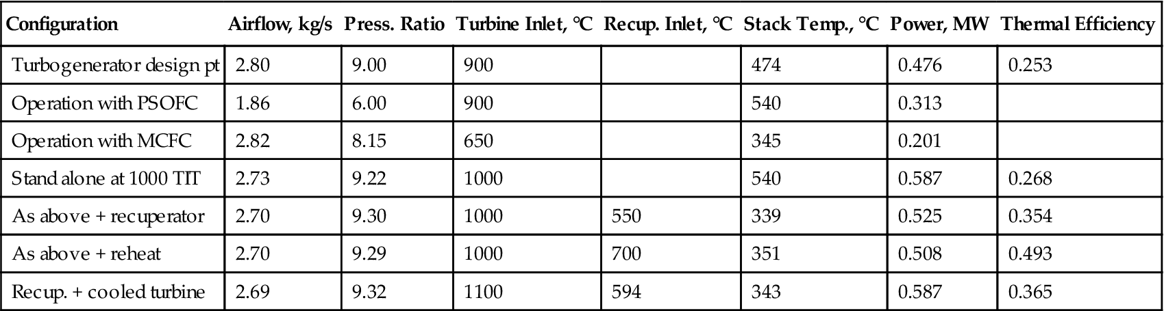
This machine will differ from any available unit by combining the following features:
Improvements in Fuel Cell Hybrids
Joint studies with fuel cell manufacturers showed that an approach for fuel cell hybrid system design by merely assembling off-the-shelf components in a simplistic “chemical plant” manner, fails to achieve a marketable product resulting in a complex and expensive system. This experience suggests that, when a higher efficiency power plant is designed, requiring several of the available fuel cell stack modules, it will be preferable to use several of the same integrated modules rather than a farm of fuel cell stack vessels connected to a single turbogenerator and balance of plant. Five of the basic 2 MW modules can be packaged into such installations, to provide plant capability of up to 10 MW size.
Fuel cell manufacturers are working to increase power density. It is anticipated that individual truckable modules will grow in power output (just as any other power plant does). This improvement would cause the turbogenerator to grow also. The baseline turbogenerator will be operating at part speed for SOFC plant initially (to avoid exceeding the best cycle pressure ratio). The likely second generation SOFC plant temperature flexibility and acceptable pressure ratio should also rise. The turbogenerator can expand its capability simply through speeding the unit up to design speed. This feature will probably accommodate 30–50% power increase.
It is anticipated that the dynamics of the turbogenerator rotor with only two radial bearings will not be amenable to the addition of a “zero stage.” So further growth of this configuration will probably be achieved by geometrical scaling. The relative merits of designing to accommodate a zero-stage (possibly adding a third radial bearing) versus accepting the change through scaling will be evaluated.
Performance Comparison with Available Turbogenerators
There are several aero-derivative turbomachinery spools of approximately the same mass flow and pressure ratio as proposed. However, these fall short of the requirement specified earlier. The undesirable features of these aeroderivatives that need to be modified are: (1) contact bearings and rotating assemblies with many separate elements, (2) gear-driven generators, (3) gas paths to be directly compatible with connection to the fuel cell system in place of the usual combustor, (4) expensive aviation hardware which offsets cost reductions that may accrue from volume production, and (5) an older style design, using a combination of axial stages and a radial impeller to achieve the same duty served by an impeller alone.
The proposed generator extends the range of high-speed direct drive alternator products, from the 30–100 kW range (now being introduced in microturbines) to >0.5 MW. This is a significant technology enhancement step and is expected to be an important development in a continuing evolution to higher direct drive generation, which is paced economically by progressive decreases in power conditioning system prices.
The improvements for fuel cell hybrids provided by the proposed system (see Table 16–8) are:
TABLE 16–8
A Comparison of Performance of the Proposed Turbogenerator with Existing Units [16-7]
| Manufacturer/Model | Airflow, kg/s | Press. Ratio | Turbine Inlet, °C | Recup. Inlet, °C | Stack Temp., °C | Power, MW | Thermal Efficiency |
| Proposed | |||||||
| Baseline simplecycle unit | 2.73 | 9.22 | 1000 | 540 | 0.587 | 0.268 | |
| Unit + recuperator | 2.70 | 9.30 | 1000 | 550 | 339 | 0.525 | 0.354 |
| Simple cycle existing | |||||||
| ASE8-1000∗ | 3.58 | 10.6 | 935 | 496 | 0.548 | 0.221 | |
| Volvo VT600∗ | 3.58 | 8.9 | 977 | 538 | 0.670 | 0.235 | |
| P&W ST6L-795∗ | 3.22 | 7.4 | 1000∼ | 589 | 0.678 | 0.247 | |
| Recuperated existing | |||||||
| Capstone microturbine(1) | 0.27∼ | 3.25∼ | 880∼ | 600∼ | 271(1) | 0.028(1) | 0.259(1) |
| GM404 Patriot (ISO day) | 1.82 | 4.3 | 1020 | 700∗∗ | 313 | 0.240 | 0.315 |
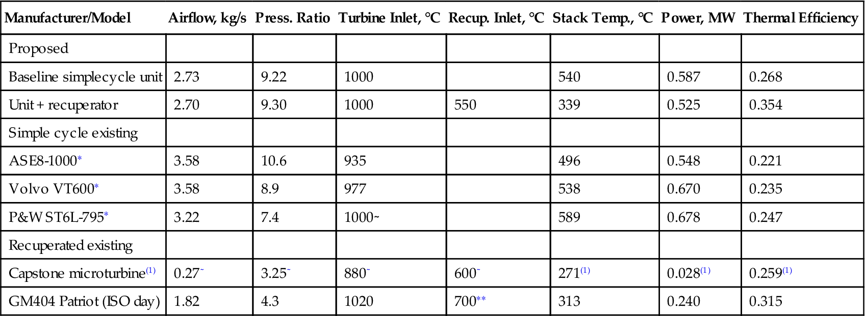
∗Data taken from Gas Turbine World 1998–1999 Performance specs.
∗∗Used a metal regenerator rather than a recuperator.
(1)From Capstone website.
∼Approximate.
• Much improved durability and reliability for the turbogenerator
• High pressure ratio (relative to micro-turbines) improves fuel cell hybrid efficiency
• Lower first cost, particularly as the turbogenerator production volume increases
• Easier integration into the fuel cell hybrid plant gas path
• Better environmental quality, both by eliminating oil usage and by maximizing plant efficiency
• Direct drive gives better cycle control during load following
Market for the Turbogenerator
Based on experience in working with prospective fuel cell manufacturers, we have seen that the microturbines being developed for one sector of the distributed generation market are an enabling technology for very small fuel cell hybrid systems. But these are not big enough to serve a commercially attractive plant. The availability of the correct size turbogenerator with promises of good durability has been of great importance to early fuel cell hybrid designs. Some fuel cell hybrids have actually been designed to fit the available microturbines.
With flexibility to serve a variety of the planned fuel cell hybrids, it is believed that an assured US fuel cell hybrid market exists, arising with the success of fuel cells. There is promise that these small turbogenerators will support plant in sizes from 0.8 MW up to 12 MW through 2010 and beyond.
The merits of a nominal 1 MW class stand-alone generator of direct drive design include local power quality improvement. Very low emissions (uncooled turbine will be run at emissions-favorable temperature), low weight, good efficiency by recuperation or CHP (suitable exhaust temperature), and low noise and vibration, will make this unit a good candidate to displace many diesel generator sets. This would result in a large production volume.
As fuel cell stack technology improves, and the power generated in a transportable modular unit increases, a need will develop for a turbogenerator having a higher unit flow capacity and power than the machine proposed. With this in mind, the turbogenerator design will be laid out, as far as is possible, for literal geometrical scalability, to facilitate low cost derivation. One product of the program will be the understanding of the extent to which this is feasible.
Preliminary configuration studies are being conducted under contract DE-FC26-00NT40914 for the US DOE. These incorporate cell manufacturer and DOE inputs to selection of the best duty cycle, and determine a mechanical design with acceptable dynamic and durability characteristics. Particular attention will be given to non-contact bearing selection and direct drive alternator design.
There is a need to provide a new high-quality, low-cost, long-life turbogenerator to be compatible with hybrid fuel cell systems for the following reasons:
1. There is a good possibility that a single machine can have wide applicability to the various US manufactured fuel cell system modules anticipated.
2. Though individual module power may only be 1–3 MW, larger plant installations will probably use multiples of the base module, up to 10 MW.
3. The proposed turbogenerator will support some system power growth, but design evaluation is required to determine whether scaling is required to support growth beyond 50% power increase in fuel cells.