
Chapter 13. Troubleshooting Cisco Unity Express
Upon completing this chapter, you will be able to do the following:
![]() Describe the areas where you can start troubleshooting, depending on the issue classification
Describe the areas where you can start troubleshooting, depending on the issue classification
![]() Describe how to follow a voice-mail call logically through the system
Describe how to follow a voice-mail call logically through the system
![]() Describe the Cisco Unity Express troubleshooting tools
Describe the Cisco Unity Express troubleshooting tools
![]() Describe logging in Cisco Unity Express
Describe logging in Cisco Unity Express
![]() Describe the Cisco Unity Express trace tool
Describe the Cisco Unity Express trace tool
![]() Describe the Cisco Unity Express trace command
Describe the Cisco Unity Express trace command
![]() Describe how to enable Cisco Unity Express trace options using the GUI
Describe how to enable Cisco Unity Express trace options using the GUI
![]() Describe how to troubleshoot the SIP integration of Cisco Unity Express and Cisco Unified Communications Manager Express
Describe how to troubleshoot the SIP integration of Cisco Unity Express and Cisco Unified Communications Manager Express
![]() Describe a SIP call flow between Cisco Unified Communications Manager Express and Cisco Unity Express
Describe a SIP call flow between Cisco Unified Communications Manager Express and Cisco Unity Express
![]() Describe a SIP troubleshooting issue
Describe a SIP troubleshooting issue
![]() Describe an MWI troubleshooting scenario
Describe an MWI troubleshooting scenario
![]() Describe an example mailbox troubleshooting scenario
Describe an example mailbox troubleshooting scenario
![]() Describe how to troubleshoot TUI scripts and subscriber input
Describe how to troubleshoot TUI scripts and subscriber input
This chapter describes how to troubleshoot issues within a Cisco Unity Express voice-mail solution using Cisco Unified Communications Manager (CUCM) Express as the call-processing system.
Call Processing to Messaging System Call Flow
This section shows the areas where you can start troubleshooting, depending on the issue classification.
When troubleshooting, it is a good idea to identify the main areas and to focus on the key components. Figure 13-1 illustrates a high-level flow of Unity Express call processing.
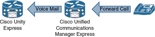
A detailed understanding of the sequence of events is also useful. Looking in depth at a specific area may not be helpful. For example, consider a situation where voice-mail calls do not arrive at Cisco Unity Express. Detailed Cisco Unity Express troubleshooting is not necessary because the problem area must be located somewhere earlier in the sequence of events—perhaps in CUCM Express. To troubleshoot calls that are forwarded to voice mail, the key areas are as follows:
![]() CUCM Express
CUCM Express
![]() IP phone configuration: Is the phone configuration correct and are the phones correctly registered? Changes for Session Initiation Protocol (SIP) phones require creating new configuration profiles and a reset of the phones.
IP phone configuration: Is the phone configuration correct and are the phones correctly registered? Changes for Session Initiation Protocol (SIP) phones require creating new configuration profiles and a reset of the phones.
![]() Voice-mail dial peer: The dial peer to voice mail has certain requirements, for example, SIP, DTMF settings, and the codec G.711.
Voice-mail dial peer: The dial peer to voice mail has certain requirements, for example, SIP, DTMF settings, and the codec G.711.
![]() Cisco Unity Express
Cisco Unity Express
![]() Voice-mail application: The trigger number must be set up and match the destination pattern on the dial peer to be able to accept the calls. There must be enough sessions available to the application to prevent call blocking.
Voice-mail application: The trigger number must be set up and match the destination pattern on the dial peer to be able to accept the calls. There must be enough sessions available to the application to prevent call blocking.
![]() Subscriber configuration: The user must be configured with a mailbox. The mailbox must be enabled and unlocked.
Subscriber configuration: The user must be configured with a mailbox. The mailbox must be enabled and unlocked.
CUCM Express
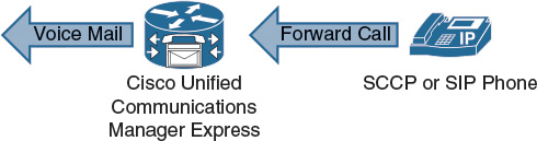
This section describes how to follow a voice-mail call logically through the system.
Always verify the CUCM Express configuration and the phone setup. Note the call flow to voice mail, as shown in Figure 13-2.
As an example, note the following key configuration commands required to route to voice mail shown in Example 13-1.
The troubleshooting sequence could begin from the ephone-dn call forwarding configuration and go to the voice-mail dial peer, or a direct call where the user presses the Messages button on the phone.
Example 13-1 CUCME Dial Peers to CUE
dial-peer voice 4500 voip
description voicemail CUE
destination-pattern 45..
session protocol sipv2
session target ipv4:10.1.130.2
dtmf-relay sip-notify
codec g711ulaw
no vad
telephony-service
voicemail 4500
ephone-dn 1
number 4001
call-forward noan 4500 timeout 10
Troubleshooting can be simplified by following the voice-mail sequence of events and the associated CUCM Express configuration. For example, calls are forwarded from an individual phone to the voice-mail extension. The voice-mail extension is defined as a destination pattern in the voice-mail dial peer, which specifies the Cisco Unity Express IP address as the session target.
The most likely reasons for a reorder tone are the following:
![]() Cisco Unity Express not set up and initialized.
Cisco Unity Express not set up and initialized.
![]() The trigger number for the voice-mail application not set or is incorrect.
The trigger number for the voice-mail application not set or is incorrect.
![]() No ports are available for the voice-mail application.
No ports are available for the voice-mail application.
![]() The wrong codec is used or transcoders are not working properly.
The wrong codec is used or transcoders are not working properly.
Use show commands to verify CUCM Express configuration and operation:
![]() show telephony-service ephone-dn
show telephony-service ephone-dn
![]() show dial-peer voice summary
show dial-peer voice summary
![]() show call history voice
show call history voice
![]() show call active voice
show call active voice
The CUCM Express debug commands can be turned on and off independently for specific modules. Each module has several options that can be turned on individually. For example, the debug voip module has many options, including the dialpeer option.
By default, the debug output is sent to the CUCM Express router console. No debug output will be displayed if the administrator uses Telnet or Secure Shell (SSH) to access the router. Use the terminal monitor command to direct debug output to Telnet or SSH. Debug settings return to their default if the router is rebooted. By default, all debugging options are off.
The following are some useful debug commands for troubleshooting CUCM Express voice-mail integration issues:
![]() The debug ephone command is useful for troubleshooting IP phones.
The debug ephone command is useful for troubleshooting IP phones.
![]() The debug voice command is useful for troubleshooting voice problems.
The debug voice command is useful for troubleshooting voice problems.
![]() The debug voip command is useful for troubleshooting VoIP.
The debug voip command is useful for troubleshooting VoIP.
To debug the voice call control API, use the debug voip ccapi privileged EXEC command. To trace the execution path through the call control API, use the debug voip ccapi inout command. The call control application programming interface (API) serves as the interface between the call session application and the underlying network-specific software. This command shows how a call flows through the system.
Use the debug ccsip command to troubleshoot problems with SIP. The calls option traces the SIP call details as they are updated in the SIP call control block. The all option displays all SIP-related debug information. Use the messages option to view SIP messages.
Cisco Unity Express Troubleshooting
The GUI, although effective for day-to-day additions, moves, and changes, is not an effective tool for troubleshooting the Cisco Unity Express system. You can use the GUI for reporting, to reload Cisco Unity Express, view system configuration, refresh MWI lights if they are out of synchronization, and turn on the tracing function. To effectively troubleshoot, you must use the CLI tools and functions.
There are three categories of tools that can be used from the Cisco Unity Express CLI. The first category is the show commands. Use the many available show commands to view the configuration, settings, and status of the Cisco Unity Express system.
Logging messages is another troubleshooting tool that you can use to diagnose a problem. The unsolicited messages that come out of the system have a severity level that is associated with them. These messages usually go to an internal login memory or to an external syslog server, if configured.
Tracing is the equivalent of debugging in Cisco IOS Software. Summary information to detailed information is displayed on the screen, sent to a syslog server, or stored in memory. Use the trace tools to focus on a specific aspect of the system.
To start troubleshooting Cisco Unity Express, use the show errors command to see which components of the system have errors. Invoke the problem that is occurring, if it is repeatable, and try to identify which modules are increasing the error counters.
Then, use the show logs command to view the logs and the show log name log-name command to view the contents of the log files. This information may further define the problem or component that is causing the errors.
Logging
This section describes logging in Cisco Unity Express.
There are four levels of output within the logging functions of Cisco Unity Express. These levels are listed here in order, from least significant to most significant:
![]() Info: Informational messages and notices
Info: Informational messages and notices
![]() Warning: Events that may require attention
Warning: Events that may require attention
![]() Error: Significant events that can affect functions
Error: Significant events that can affect functions
![]() Fatal: Critical alerts and emergencies that can affect the stability of the system
Fatal: Critical alerts and emergencies that can affect the stability of the system
By default, a Cisco Unity Express Network Module system sends all four categories of logging messages to a messages.log file on the hard disk or flash. The message.log text file is limited to a 100-MB maximum size. A history of two message log files is kept as follows:
![]() When the message.log file reaches a set size, the system renames it messages.log.prev and starts a new messages.log file.
When the message.log file reaches a set size, the system renames it messages.log.prev and starts a new messages.log file.
![]() When the messages.log file once again reaches a predetermined size, the old messages.log.prev is deleted. The current messages.log file is renamed messages.log.prev, and another new messages.log file is created. This loop continues indefinitely.
When the messages.log file once again reaches a predetermined size, the old messages.log.prev is deleted. The current messages.log file is renamed messages.log.prev, and another new messages.log file is created. This loop continues indefinitely.
The logging output can be directed to the following three destinations:
![]() Messages.log: The logging messages can be sent to this text file, which resides on the storage of the Cisco Unity Express module. This action is the default.
Messages.log: The logging messages can be sent to this text file, which resides on the storage of the Cisco Unity Express module. This action is the default.
![]() Console: Real-time messages or historical logs that can be displayed on the Cisco Unity Express console.
Console: Real-time messages or historical logs that can be displayed on the Cisco Unity Express console.
![]() Syslog: The logging messages can be sent to an external syslog server.
Syslog: The logging messages can be sent to an external syslog server.
![]() Equivalent of Cisco IOS Software debug command
Equivalent of Cisco IOS Software debug command
![]() Composed of modules
Composed of modules
![]() Modules are composed of one or more entities.
Modules are composed of one or more entities.
![]() Entity may have one or more activities under it.
Entity may have one or more activities under it.
![]() Output to trace buffer or stored in atrace.log file
Output to trace buffer or stored in atrace.log file
![]() Used as temporary troubleshooting tool
Used as temporary troubleshooting tool
Although logging consists of unsolicited messages, tracing is configured by the administrator. Tracing in Cisco Unity Express is the equivalent of using debug commands in Cisco IOS Software.
Knowledge of the system architecture is useful for understanding the structures within the trace settings. Within trace, there are modules. Within the modules, there are entities. Entities are composed of one or more activities. When configuring tracing, the administrator can enable all of these entities or any combination of these entities.
The trace output is stored in the atrace.log, which is stored on the storage of the Cisco Unity Express module.
Use the log trace local enable command to allow the trace buffer to be written to flash:
CUE (config)# log trace local enable
CUE# show trace
MODULE ENTITY SETTING
config-ccn sip-subsystem 00000001
config-ccn jtapi-subsystem 00000001
config-ccn sip-trigger 00000001
...
LOG NAME STATUS
atrace.log enabled
Note
Turning on excessive tracing can cause performance issues in the Cisco Unity Express system. Use tracing only as a temporary troubleshooting tool. Turn off tracing when the relevant output has been gathered.
Using trace Commands via CLI
To enable tracing from the CLI, use the trace command. The trace command can be used to turn on a specific trace entity, a whole trace module, or all tracing. Turning on tracing for a higher-level object overrides tracing of lower-level objects.
Much like debugging in Cisco IOS Software on a router, tracing does not survive the reboot of Cisco Unity Express. The trace setting returns to its defaults on a reboot. The no trace all command turns tracing off.
Example 13-2 shows how to view the trace command options.
Example 13-2 CUE Trace Options
CUE# trace ?
vmclient Module
aaa Module
voiceview-ccn Module
management Module
um2 Module
sysdb Module
operation Module
editorexpress Module
BackupRestore Module
configapi Module
gateway Module
dbclient Module
ccn Module
config-ccn Module
snmp Module
voicemail Module
all Every module, entity and activity
rest Module
ums Module
security Module
imap Module
udppacer Module
caff-sip Module
voiceview Module
capi Module
entityManager Module
smtpclient Module
webInterface Module
limitsManager Module
webapp Module
license Module
eecompiler Module
superthread Module
networking Module
sitemanager Module
csta Module
ntp Module
dns Module
The copy log logname url url command is used to copy the logging files to a server, such as an FTP server. Once copied, the text-based log files can be viewed using a text editor.
Because the amount of information in the file can be significant, the search features of text editors can be useful for finding specific information or time stamps.
The trace.log trace output file is not text-based and cannot be viewed using a text editor. It may be necessary to send the trace.log file to Cisco when requested by technical support.
The log server address {ip-address | hostname} command is used to configure an external server for saving log messages.
If no syslog server is present in the network, the logging messages that are stored in the log file can be viewed by sending the messages.log file to an FTP server. After the file is on the server, you can view the file by using any text editor. Using a text editor is much easier than trying to view the messages.log file on the console of the Cisco Unity Express system. To save the trace configuration upon rebooting, use the log trace boot command.
To display a list of events in memory, use the show trace buffer command in Cisco Unity Express EXEC mode. Stop the output by pressing Ctrl+C. The trace buffer in memory can be up to 10 MB in size. To display a list of events from the atrace.log file, use the show trace store command in Cisco Unity Express EXEC mode.
To trace large amounts of data, send the information directly to the FTP server. Offline traces have the least performance impact. This activity is accomplished from configuration mode as follows:
![]() Use the log trace server url command to define the FTP server.
Use the log trace server url command to define the FTP server.
![]() Use the log trace server enable command to enable trace output to the FTP server.
Use the log trace server enable command to enable trace output to the FTP server.
Note
Issue the show trace buffer tail command to view trace information in real time.
GUI Macro Feature
Figure 13-3 illustrates how to enable Cisco Unity Express trace options using the GUI.
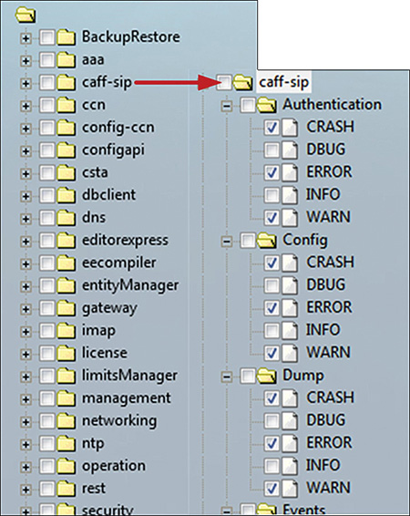
To enable Cisco Unity Express trace options using the GUI, choose Administration > Traces. The window displays a hierarchical listing of the system components.
To enable a trace on a system component, check the check box next to the name of the component. To expand the listing of components, click the plus (+) sign next to the upper-level components. Check the box next to an upper-level component (a module or entity) to enable the traces for all of the components under that component. Uncheck the box next to an upper-level component to disable the traces for all of the components under that component.
Note
The GUI and CLI have the same trace options. However, traces cannot be viewed from the GUI.
The Cisco Unity Express GUI macro feature speeds up the process of selecting trace options. When selecting a trace module, the macro automatically selects the individual suboptions. For example, after selecting the voice-mail check box, all nested boxes are also checked. Individual options can be checked or unchecked at the micro level.
SIP Troubleshooting
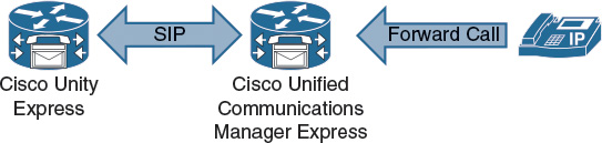
CUCM Express and Cisco Unity Express communicate via SIP, as illustrated in Figure 13-4.
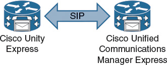
This method of communication means that voice-mail integration issues require troubleshooting of SIP between these systems. Verify that SIP configuration parameters, such as IP address and protocol version (SIP Version 2), are the same for both systems.
SIP Call Flow
Figure 13-5 shows a SIP call flow between CUCM Express and Cisco Unity Express.
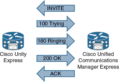
SIP uses different message types to initiate and control voice calls. The SIP request messages are as follows:
![]() INVITE: This message indicates that a user or service is being invited to participate in a call session.
INVITE: This message indicates that a user or service is being invited to participate in a call session.
![]() ACK: This message confirms that a client has received a final response to an INVITE request.
ACK: This message confirms that a client has received a final response to an INVITE request.
![]() BYE: This message terminates an existing call, and can be sent by either user agent (UA).
BYE: This message terminates an existing call, and can be sent by either user agent (UA).
![]() CANCEL: This message cancels pending searches, but does not terminate calls that have been accepted.
CANCEL: This message cancels pending searches, but does not terminate calls that have been accepted.
![]() OPTIONS: This message queries the capabilities of servers.
OPTIONS: This message queries the capabilities of servers.
![]() REGISTER: This message registers the UA with the registrar server of a domain.
REGISTER: This message registers the UA with the registrar server of a domain.
The SIP response messages are numbered and grouped in the following ranges:
![]() 1xx: Information
1xx: Information
![]() 2xx: Successful responses
2xx: Successful responses
![]() 3xx: Redirection responses
3xx: Redirection responses
![]() 4xx: Request failure responses
4xx: Request failure responses
![]() 5xx: Server failure responses
5xx: Server failure responses
![]() 6xx: Global responses
6xx: Global responses
The SIP INVITE message initiates the call setup between CUCM Express and Cisco Unity Express. The INVITE message direction depends on which side originates the call. The SIP 200 OK message is sent when the call is answered.
The following summarizes a successful SIP call setup:
![]() Send INVITE message.
Send INVITE message.
![]() Receive 100 Trying.
Receive 100 Trying.
![]() Receive 180 Ringing.
Receive 180 Ringing.
![]() Send 200 OK.
Send 200 OK.
![]() Receive ACK.
Receive ACK.
The following summarizes a successful SIP call clearing:
![]() Send BYE message.
Send BYE message.
![]() Receive 200 OK.
Receive 200 OK.
![]() Receive ACK.
Receive ACK.
Note
Refer to RFC 3261 for more information about the SIP message types.
Common SIP configuration problems are the following:
![]() Incorrect IP address for Cisco Unity Express.
Incorrect IP address for Cisco Unity Express.
![]() Incorrect codec configuration.
Incorrect codec configuration.
![]() Wrong destination pattern is configured, so the dial peer is not triggered for voice-mail calls.
Wrong destination pattern is configured, so the dial peer is not triggered for voice-mail calls.
![]() Misconfigured dual-tone multifrequency (DTMF) relay.
Misconfigured dual-tone multifrequency (DTMF) relay.
![]() Incorrect SIP version.
Incorrect SIP version.
![]() Voice activity detection (VAD) is enabled by default. It must be disabled.
Voice activity detection (VAD) is enabled by default. It must be disabled.
To enable Cisco Unity Express SIP trace options using the GUI, navigate to the Cisco Unity Express GUI, choose Administration > Traces, and check the caff-sip macro check box.
SIP messages are the same as messages that are viewed using the Cisco IOS Software debug command. Additional internal Cisco Unity Express messages may also be displayed in trace output.
Note
Trace output is viewed via the CLI. For example, use the show trace buffer tail command to view trace output in real time.
Troubleshooting SIP Issues
In the SIP troubleshooting scenario in Figure 13-6, a company is using a Cisco Unity Express voice-mail solution with CUCM Express.
Currently, all users are experiencing problems accessing their voice mail. What may be the reason?
The problem is experienced by all voice-mail users, so the administrator suspects a problem with the voice-mail system or an integration issue. The first action is to verify the CUCM Express and Cisco Unity Express configurations. In this example, no issues are found during the initial verification of the configurations and integration between CUCM Express and Cisco Unity Express.
The next step is to look at the connection between Cisco Unity Express and CUCM Express. Use Cisco Unity Express SIP tracing to view traffic between CUCM Express and Cisco Unity Express. Alternatively, use the CUCM Express debug command to view the SIP traffic.
In this example, the codec was configured incorrectly. When debugging or tracing, take a look at the SIP INVITE message. The INVITE will contain SDP parameters for the call setup. In the trace, the INVITE and 200 OK SIP messages will have different codec types as follows:
![]() INVITE requests G.729: a = rtpmap:18 G729/8000 0
INVITE requests G.729: a = rtpmap:18 G729/8000 0
![]() 200 OK requests G.711ulaw: a = rtpmap: 0 PCMU/8000
200 OK requests G.711ulaw: a = rtpmap: 0 PCMU/8000
In a trace, the BYE message will contain a reason code for the call disconnection (cause = 65). Cause 65 indicates “bearer capability not implemented,” which indicates the wrong codec.
Additional and commonly seen cause codes include the following:
![]() Unallocated (unassigned) number = 1
Unallocated (unassigned) number = 1
![]() Normal call clearing = 16
Normal call clearing = 16
Note
See the ITU Q.850 Recommendation for a complete list of cause codes.
In this example, the dial peer is not configured to use the G.711 mu-law codec, so the default G.729 will be used. The voice-mail dial peer must be configured for G.711 mu-law using the codec dial peer configuration command to resolve the issue.
Troubleshooting MWI Issues
In this message waiting indicator (MWI) troubleshooting scenario, a company is using a Cisco Unity Express voice-mail solution with CUCM Express. Currently, voice mail is working normally. All users are able to access their voice mail. Messages can be recorded and retrieved.
The problem is that the MWI is not working, as shown in Figure 13-7.
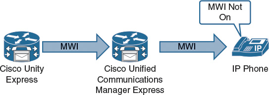
On IP phones, the MWI light does not change to indicate that there are new messages. What may cause this issue?
Occasionally, the MWI setting for a telephone can be out of synchronization with the user’s message status in the voice-mail database. For example, a user could have pending messages, but the MWI does not turn on. The administrator can refresh the MWI light so that the light reflects the current message status in the voice-mail database. Use the following procedure to refresh the MWI for a single mailbox or for all mailboxes:
![]() Choose Voice Mail > Message Waiting Indicators > Refresh.
Choose Voice Mail > Message Waiting Indicators > Refresh.
![]() To refresh one mailbox, check the box next to the user or group ID of the mailbox owner and click Refresh Selected. To refresh all mailboxes, click Refresh All.
To refresh one mailbox, check the box next to the user or group ID of the mailbox owner and click Refresh Selected. To refresh all mailboxes, click Refresh All.
Note
Cisco Unity Express will send MWI messages to refresh the MWI state. These messages are useful when troubleshooting or debugging MWI problems.
Enable Cisco Unity Express MWI tracing. Place a call, leave a voice-mail message, and view the trace output. Use trace voicemail mwi all command.
You may also use the CUCM Express debug ccsip message command to verify the MWI notification.
In this example, the DTMF method was not set on the dial peer in Cisco Unity Express. So, there was no match in the DTMF method configuration on CUCM Express and Cisco Unity Express.
Troubleshooting Mailbox Issues
In this mailbox troubleshooting scenario, a company is using a Cisco Unity Express voice-mail solution with CUCM Express in a medium-sized office environment. Currently, voice mail appears to be working for most users. However, few subscribers cannot access their voice mail, as shown in Figure 13-8.
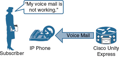
Most subscribers can use their mailbox, so it seems that voice-mail integration between CUCM Express and Cisco Unity Express is working. The first step is to verify that individual IP phones are configured correctly in CUCM Express.
Check that the IP phones that are associated with the users who are reporting problems are configured to forward calls to the correct voice-mail extension. Compare the phones that are having problems with IP phones that work.
Verify the Cisco Unity Express mailbox configuration as follows:
![]() Check that the subscriber has a mailbox associated.
Check that the subscriber has a mailbox associated.
![]() Verify that the mailbox is enabled.
Verify that the mailbox is enabled.
![]() Verify that the extension of the subscriber is designated as a primary extension. Cisco Unity Express does not send an MWI to an E.164 number.
Verify that the extension of the subscriber is designated as a primary extension. Cisco Unity Express does not send an MWI to an E.164 number.
Occasionally, a mailbox becomes locked, and the owner cannot access the stored messages. A “mailbox is currently in use” message is typically played when a user tries to access a mailbox that is locked.
To unlock the mailbox, choose Voice Mail > Mailboxes. Check the box next to the mailbox that you want to unlock and click Unlock.
If these steps do not resolve the issue, enable Cisco Unity Express Mailbox trace options using the graphical user interface (GUI). Attempt to access a mailbox and view trace output via the CLI.
Interpreting TUI Sessions
Always verify scripts and subscriber input. The script voicebrowser.aef provides the functionality of the Cisco Unity Express voice-mail application. This script uses Voice Extensible Markup Language (VXML) to implement its functionality. These functions can be viewed by using the trace voicemail vxml all command, which provides the following information:
![]() Displays received DTMF and prompts played in response to them
Displays received DTMF and prompts played in response to them
![]() Uses caller ID for differentiating different calls into voice mail
Uses caller ID for differentiating different calls into voice mail
![]() Displays voice-mail telephone user interface (TUI) position
Displays voice-mail telephone user interface (TUI) position
![]() Various levels of prompts and menus within the TUI
Various levels of prompts and menus within the TUI
The caller ID of users calling into voice mail is checked. If there is a mailbox that is associated with that phone number, users are prompted for the PIN. If there is no matching mailbox, users are prompted to enter the extension with which their mailboxes are associated.
To view a call arriving in voice mail and a message being left for a subscriber in the form of trace command output, enter the trace voicemail vxml all command. The output can include the prompts that are played and any corresponding .wav files that are mapped to those prompts. The input of the caller can also be displayed in the output of the trace command.
![]() A problem-solving methodology should be used when troubleshooting voice-mail issues in Cisco Unity Express.
A problem-solving methodology should be used when troubleshooting voice-mail issues in Cisco Unity Express.
![]() CUCM Express debug commands can be used to troubleshoot SIP connectivity issues with Cisco Unity Express.
CUCM Express debug commands can be used to troubleshoot SIP connectivity issues with Cisco Unity Express.
![]() The Cisco Unity Express MWI Refresh feature generates messages to synchronize the MWI state of IP phones. These messages are helpful for troubleshooting.
The Cisco Unity Express MWI Refresh feature generates messages to synchronize the MWI state of IP phones. These messages are helpful for troubleshooting.
![]() The trace voicemail vxml command output shows TUI input as well as menus and prompts.
The trace voicemail vxml command output shows TUI input as well as menus and prompts.
This chapter covered troubleshooting Cisco Unity Express in a CUCM Express environment.
Review Questions
Answer the following questions, and then see Appendix A, “Answers to Review Questions,” for the answers.
1. How many levels are available for logging in Cisco Unity Express?
a. 1
b. 2
c. 4
d. 5
e. 7
2. Cisco Unity Express trace files can be viewed in a text editor.
a. True
b. False
3. Which command is used to allow the trace buffer to be written to flash?
a. log trace enable
b. log trace local enable
c. log trace enable local
d. log local enable flash
4. Enabling tracing in the Cisco Unity Express GUI provides you with less trace information than using the CLI.
a. True
b. False
5. Which order is correct for a SIP call flow?
a. Invite, 100 Trying, 200 OK, ACK
b. Invite, 100 Trying, 180 Ringing, 200 OK
c. Invite, 180 Ringing, 200 OK, ACK