
Chapter 16. Integrating Cisco Unified Communications IM and Presence
Upon completing this chapter, you will be able to do the following:
![]() Describe the requirements on CUCM for integration with IMP Cisco Unified Communications IM and Presence (IM&P) with Cisco Unified Communications Manager
Describe the requirements on CUCM for integration with IMP Cisco Unified Communications IM and Presence (IM&P) with Cisco Unified Communications Manager
![]() Describe the requirements on CUCM for integration with IM&P
Describe the requirements on CUCM for integration with IM&P
![]() Describe the steps to configure CUCM for a presence integration
Describe the steps to configure CUCM for a presence integration
![]() Describe the service profile including the UC Services that are required for a user to use presence
Describe the service profile including the UC Services that are required for a user to use presence
![]() Describe the requirements on IM&P to integrate with CUCM
Describe the requirements on IM&P to integrate with CUCM
![]() Describe the steps to integrate IM&P with CUCM
Describe the steps to integrate IM&P with CUCM
![]() Describe the Cisco Unified Communications IM&P services
Describe the Cisco Unified Communications IM&P services
![]() Describe the benefits of Cisco Jabber service discovery
Describe the benefits of Cisco Jabber service discovery
![]() Describe how Cisco Jabber discovers the service domain
Describe how Cisco Jabber discovers the service domain
![]() Describe how Cisco Jabber discovers the operating mode
Describe how Cisco Jabber discovers the operating mode
![]() Describe the call flow when using Cisco UDS service records
Describe the call flow when using Cisco UDS service records
![]() Describe the DNS SRV records for Cisco Jabber
Describe the DNS SRV records for Cisco Jabber
![]() Describe the priorities and weights of the DNS SRV records
Describe the priorities and weights of the DNS SRV records
![]() Show how to verify and troubleshoot configured Cisco UDS SVR records
Show how to verify and troubleshoot configured Cisco UDS SVR records
![]() Describe the installation options for the Cisco Jabber MSI installer
Describe the installation options for the Cisco Jabber MSI installer
![]() Describe how to create a customized Cisco Jabber installer file
Describe how to create a customized Cisco Jabber installer file
This chapter describes the integration of Cisco Unified Communications Manager (CUCM) and Cisco Unified Communications IM&P. First, CUCM is prepared for integration with Cisco Unified Communications IM&P. Cisco Unified Communications IM&P is then set up to connect with CUCM and system settings are modified. Network services are then established so that Cisco Jabber can discover its domain and services. Finally, the chapter discusses the Cisco Jabber installation options.
Set Up CUCM for Presence
The components that are presented in the Figure 16-1 must be implemented on CUCM to prepare for integration with Cisco Unified Communications IM&P. These components allow a Cisco Jabber client to register, show the presence status, and reflect changes when, for example, a line is in use.

Synchronize the end users from a directory and configure the associated devices. Bind the device to the user and configure the primary extension. Verify that Computer Telephony Integration (CTI) is enabled for the device and the line. Ensure that the user has the correct CTI access control groups assigned. Finally, enable presence for the end user and assign the service profile that contains the services that were selected under UC services in the CUCM menu.
For softphone mode, Cisco Jabber must be added as a Cisco Unified Client Services Framework (CSF) device to register with CUCM. Every line that is used by a presence user must be associated with the user in the line configuration page, because the presence indicator is line-based and not device-based. This setting allows contacts to see the busy status with the message “On the Phone.”
Configure a Session Initiation Protocol (SIP) trunk security profile for a SIP trunk pointing to the Cisco Unified Communications IM&P server. There can be only one CUP SIP publish trunk selected on CUCM. In other words, one CUCM cluster can connect to only one Cisco Unified Communications IM&P cluster. However, additional Cisco Unified Communications IM&P clusters can be peered or federated.
Checklist for CUCM Setup
This section describes the steps to set up CUCM for presence integration.
The checklist below can be used as a guideline to set up the CUCM for integration with Cisco Unified Communications IM&P.
![]() Configure a SIP trunk pointing to Cisco Unified Communications IM&P:
Configure a SIP trunk pointing to Cisco Unified Communications IM&P:
![]() Add a presence-specific SIP trunk security profile.
Add a presence-specific SIP trunk security profile.
![]() Configure the Cisco Unified Communications IM&P publish trunk. (You can also configure this trunk on Cisco Unified Communications IM&P.)
Configure the Cisco Unified Communications IM&P publish trunk. (You can also configure this trunk on Cisco Unified Communications IM&P.)
![]() Activate the required services on CUCM:
Activate the required services on CUCM:
![]() Cisco AXL service
Cisco AXL service
![]() CTI Manager
CTI Manager
CUCM and Cisco Unified Communications IM&P are connected via a SIP trunk. The SIP trunk must be enabled to support presence information. To specify these presence settings, add a SIP trunk security profile and enable the following four check boxes:
![]() Check the Accept Presence Subscription check box to accept presence subscription requests that come via the SIP trunk.
Check the Accept Presence Subscription check box to accept presence subscription requests that come via the SIP trunk.
![]() Check the Accept Out-of-Dialog Refer check box to accept incoming non-INVITE, Out-of-Dialog REFER requests that come via the SIP trunk.
Check the Accept Out-of-Dialog Refer check box to accept incoming non-INVITE, Out-of-Dialog REFER requests that come via the SIP trunk.
![]() Check the Accept Unsolicited Notification check box to accept incoming non-INVITE, unsolicited notification messages that come via the SIP trunk.
Check the Accept Unsolicited Notification check box to accept incoming non-INVITE, unsolicited notification messages that come via the SIP trunk.
![]() Check the Accept Replaces Header check box to accept new SIP dialogs that have replaced existing SIP dialogs.
Check the Accept Replaces Header check box to accept new SIP dialogs that have replaced existing SIP dialogs.
The settings that are not mentioned are not required or can be left with the default settings for an integration with Cisco Unified Communications IM&P.
Configure the SIP trunk pointing to Cisco Unified Communications IM&P and select the previously configured SIP trunk security profile. In the SIP Information configuration area, set the following parameters:
![]() Destination Address: The destination address represents the remote SIP peer with which the trunk will communicate; in this case, the Cisco Unified Communications IM&P server. Use the FQDN or IP address. SIP trunks only accept incoming requests from the configured destination address and the incoming port that is specified in the SIP trunk security profile that is associated with this trunk. The default port is 5060 for SIP. Make sure that DNS servers and domains are set up in both systems when using FQDNs.
Destination Address: The destination address represents the remote SIP peer with which the trunk will communicate; in this case, the Cisco Unified Communications IM&P server. Use the FQDN or IP address. SIP trunks only accept incoming requests from the configured destination address and the incoming port that is specified in the SIP trunk security profile that is associated with this trunk. The default port is 5060 for SIP. Make sure that DNS servers and domains are set up in both systems when using FQDNs.
![]() BLF Presence Group: The presence group does not affect the Cisco Unified Communications IM&P integration. The same is true for the SUBSCRIBE calling search (CSS).
BLF Presence Group: The presence group does not affect the Cisco Unified Communications IM&P integration. The same is true for the SUBSCRIBE calling search (CSS).
The settings that are not mentioned are not required for integration with Cisco Unified Communications IM&P. However, you must set standard settings such as device pools and other mandatory SIP trunk settings.
Configure the IM&P Publish Trunk in the Cisco CallManager service parameters. This parameter can be set on Cisco Unified Communications IM&P as well. The IM&P Publish Trunk parameter specifies the SIP trunk that CUCM uses to send PUBLISH messages that pertain to the presence activities in Cisco Unified Communications IM&P.
Cisco Unified Communications IM&P reads out information from the CUCM database via the AXL. Verify that the AXL service is activated on CUCM. For deskphone mode, you must also enable the CTI Manager service to control the desk phones with Computer Telephony Integration Quick Buffer Encoding (CTIQBE).
Cisco Jabber UC Services
Figure 16-2 illustrates the service profile including the UC Services options for a user to use presence.

UC services are configured in CUCM Administration beginning with CUCM Version 9. Before Version 9, all user profile settings for presence were configured in the Cisco Unified Presence server.
After configuring the UC services, you can group them into service profiles that you associate with end users. After end users have a service profile, their clients can download this profile for seamless integration with the configured Unified Communications services.
The following briefly describes the Unified Communications services that are configured in CUCM:
![]() Voice mail: The voice-mail service specifies the product type. The available options are Cisco Unity and Cisco Unity Connection. The default port is 443. Cisco recommends that you use HTTPS as the voice-mail transport protocol for Cisco Unity Connection.
Voice mail: The voice-mail service specifies the product type. The available options are Cisco Unity and Cisco Unity Connection. The default port is 443. Cisco recommends that you use HTTPS as the voice-mail transport protocol for Cisco Unity Connection.
![]() Mailstore: Cisco Jabber clients use the mailstore service for visual voice-mail functionality. The default port number is 143. For secure voice messaging with Cisco Unity Connection, use port 7993.
Mailstore: Cisco Jabber clients use the mailstore service for visual voice-mail functionality. The default port number is 143. For secure voice messaging with Cisco Unity Connection, use port 7993.
![]() Conferencing: Choose a product type that applies to your network configuration. One of the available options among others is Cisco WebEx. Use port 80 for HTTP and port 443 for HTTPS communications.
Conferencing: Choose a product type that applies to your network configuration. One of the available options among others is Cisco WebEx. Use port 80 for HTTP and port 443 for HTTPS communications.
![]() Directory: Choose the product type directory or enhanced directory. The default port is 389. The enhanced directory is only used when connecting to CUCM UDS.
Directory: Choose the product type directory or enhanced directory. The default port is 389. The enhanced directory is only used when connecting to CUCM UDS.
![]() IM&P: Choose a supported IM&P product type. The available options are Unified Communications Manager (IM&P) or WebEx (IM&P).
IM&P: Choose a supported IM&P product type. The available options are Unified Communications Manager (IM&P) or WebEx (IM&P).
![]() CTI: Soft clients use the CTI service for deskphone control. The default port is 2748.
CTI: Soft clients use the CTI service for deskphone control. The default port is 2748.
![]() Video Conference Scheduling Portal: The only product supported at the time of the writing is Telepresence Management System.
Video Conference Scheduling Portal: The only product supported at the time of the writing is Telepresence Management System.
Implementing Cisco Unified Communications IM&P
Figure 16-3 shows the parameters that are related to different requirements of a Cisco Unified Communications IM&P implementations.
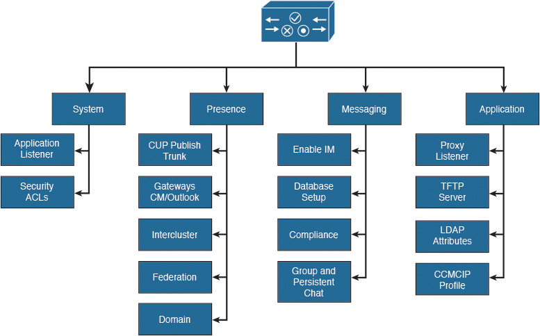
The application listener settings must match the SIP settings (especially the port) that are configured on CUCM. In addition, you can optimize the presence behavior, enable or disable presence availability, or limit the number of contacts.
Messaging can be set up with a database to log all messages for archiving and compliance. For Cisco Jabber, the TFTP server and CUCM IP Phone (CCMCIP) profile must be set so that the client can retrieve its configuration file and the list of controlled devices.
Checklist for Cisco Unified Communications IM&P Setup
Follow this checklist to set up Cisco Unified Communications IM&P for presence integration:
![]() Add CUCM as a presence gateway.
Add CUCM as a presence gateway.
![]() Configure and select the SIP TCP listener and enable event routing.
Configure and select the SIP TCP listener and enable event routing.
![]() Verify the domain settings.
Verify the domain settings.
![]() Activate the required services.
Activate the required services.
![]() Run the system troubleshooter to verify the integration.
Run the system troubleshooter to verify the integration.
On Cisco Unified Communications IM&P, add CUCM as the presence gateway. This action allows Cisco Unified Communications IM&P to know where to send the presence information. The IM&P service will then trigger the CUCM (or Exchange as a presence gateway for calendar integration) to publish phone presence information when the line status is changed or, on initial synchronization, when subscribing to presence information.
The SIP TCP listener is the Cisco Unified Communications IM&P component that receives SIP messages. Verify that the preconfigured Default Cisco SIP Proxy TCP Listener on Cisco Unified Communications IM&P has the same parameters that are configured in CUCM in the SIP trunk and SIP trunk security profile. Application listeners carry requests to Cisco Unified Communications IM&P services and control request routing behavior. In addition, turn on method/event routing. If this setting is turned off, users cannot share their availability.
Verify the domain settings and specify the DNS domain name. Typically, the domain name should be a top-level enterprise domain name (for example, cisco.com). Then activate the necessary services.
Cisco Unified Communications IM&P has a system troubleshooter that executes more than 60 tests to see if the integration was successful for different modules and features in Cisco Unified Communications IM&P.
Cisco Unified Communications IM&P Services
In Cisco Unified Communications IM&P Serviceability, navigate to Tools > Service Activation and note the services, as shown in Figure 16-4.
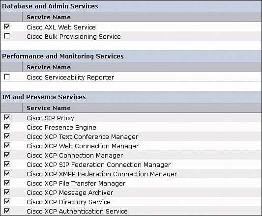
Review the service description and enable only the required services instead of simply enabling all services to optimize the resource utilization. When not configured or configured incorrectly, some services stop after a short time.
Database and administrative services are the following:
![]() Cisco AXL Web Service: Cisco AXL Web Service is enabled by default on all cluster nodes. Cisco recommends that you always leave the service activated on the IM&P database publisher node. This service communicates with CUCM to exchange database information.
Cisco AXL Web Service: Cisco AXL Web Service is enabled by default on all cluster nodes. Cisco recommends that you always leave the service activated on the IM&P database publisher node. This service communicates with CUCM to exchange database information.
![]() Cisco Bulk Provisioning Service: If you use the BAT to administer users, you must turn on this service.
Cisco Bulk Provisioning Service: If you use the BAT to administer users, you must turn on this service.
Performance and monitoring services are the following:
![]() Cisco Serviceability Reporter: The service only generates reports on the publisher node even if you turn on the service on other nodes.
Cisco Serviceability Reporter: The service only generates reports on the publisher node even if you turn on the service on other nodes.
IM&P services are the following:
![]() Cisco SIP Proxy and Cisco Presence Engine: Activate these services on all nodes in the cluster to enable presence functionality.
Cisco SIP Proxy and Cisco Presence Engine: Activate these services on all nodes in the cluster to enable presence functionality.
![]() Cisco XCP Text Conference Manager: Turn on this service if you deploy the chat feature on Cisco Unified Communications IM&P. The permanent chat feature requires an external database. If you enable the permanent chat feature, you must also configure an external database before starting the Text Conference Manager service. The Text Conference Manager service will not start if the permanent chat feature is enabled and an external database is not configured.
Cisco XCP Text Conference Manager: Turn on this service if you deploy the chat feature on Cisco Unified Communications IM&P. The permanent chat feature requires an external database. If you enable the permanent chat feature, you must also configure an external database before starting the Text Conference Manager service. The Text Conference Manager service will not start if the permanent chat feature is enabled and an external database is not configured.
![]() Cisco XCP Web Connection Manager: Turn on this service if you integrate XMPP-based application programming interface (API) web clients with IM&P (for example Cisco Jabber Messenger for the Web, which works with any web browser).
Cisco XCP Web Connection Manager: Turn on this service if you integrate XMPP-based application programming interface (API) web clients with IM&P (for example Cisco Jabber Messenger for the Web, which works with any web browser).
![]() Cisco XCP Connection Manager: Turn on this service if you integrate XMPP clients with Cisco Unified Communications IM&P.
Cisco XCP Connection Manager: Turn on this service if you integrate XMPP clients with Cisco Unified Communications IM&P.
![]() Cisco XCP SIP Federation Connection Manager: Turn on this service if you deploy a federation over SIP (for example, to a Microsoft Skype for Business domain).
Cisco XCP SIP Federation Connection Manager: Turn on this service if you deploy a federation over SIP (for example, to a Microsoft Skype for Business domain).
![]() Cisco XCP XMPP Federation Connection Manager: Turn on this service only if you deploy a federation over the XMPP protocol to another Cisco Unified Communications IM&P domain or any other XMPP domain.
Cisco XCP XMPP Federation Connection Manager: Turn on this service only if you deploy a federation over the XMPP protocol to another Cisco Unified Communications IM&P domain or any other XMPP domain.
![]() Cisco XCP Message Archiver: Turn on this service if you deploy the compliance feature on IM&P. If you turn on the Message Archiver before you configure an external database, the service will not start.
Cisco XCP Message Archiver: Turn on this service if you deploy the compliance feature on IM&P. If you turn on the Message Archiver before you configure an external database, the service will not start.
![]() Cisco XCP File Transfer Manager: Turn
Cisco XCP File Transfer Manager: Turn
![]() Cisco XCP Directory Service: Turn on this service if you integrate XMPP clients on IM&P with an LDAP directory. If you turn on the Directory Service before you configure the Lightweight Directory Access Protocol (LDAP) contact search settings for third-party XMPP clients, the service will start and then stop again.
Cisco XCP Directory Service: Turn on this service if you integrate XMPP clients on IM&P with an LDAP directory. If you turn on the Directory Service before you configure the Lightweight Directory Access Protocol (LDAP) contact search settings for third-party XMPP clients, the service will start and then stop again.
![]() Cisco XCP Authentication Service: Turn on this service if you integrate XMPP clients with IM and Presence.
Cisco XCP Authentication Service: Turn on this service if you integrate XMPP clients with IM and Presence.
Cisco Jabber Service Discovery
This section describes the benefits of Cisco Jabber service discovery. While optional for Jabber to register to CUCM, the benefits of Jabber service discovery are as follows:
![]() Enables Cisco Jabber to automatically acquire client configuration:
Enables Cisco Jabber to automatically acquire client configuration:
![]() Unified Communications services domain
Unified Communications services domain
![]() Operating mode (on-premises, cloud, or hybrid)
Operating mode (on-premises, cloud, or hybrid)
![]() Operating location (inside or outside corporate network)
Operating location (inside or outside corporate network)
![]() Home cluster in multicluster environment
Home cluster in multicluster environment
![]() Enhances end user experience:
Enhances end user experience:
![]() No prompt to ask for configurations
No prompt to ask for configurations
![]() Reduces support calls due to misconfiguration
Reduces support calls due to misconfiguration
![]() Cisco Jabber cross-platform initiative:
Cisco Jabber cross-platform initiative:
![]() Windows, Mac OS X
Windows, Mac OS X
![]() iOS and Android
iOS and Android
To make Cisco Jabber rollouts easy to execute, Cisco Jabber discovers its services based on DNS SRV records. Depending on the DNS answer, the client knows whether it is located inside or outside of the enterprise and also if it connects to cloud or on-premises solution.
After receiving DNS information, Cisco Jabber can connect to the appropriate system (for example, CUCM) and download its configuration file including information about all controllable devices. Depending on the mode, the client registers with CUCM (phone-only and softphone mode) or with Cisco Unified Communications IM&P (deskphone mode).
Because Cisco Jabber has service discovery, there is no need to configure any device settings on the client for login.
Service Discovery: Domain
This section describes how Cisco Jabber discovers the service domain. The two options to discover the domain are as follows:
![]() Option 1
Option 1
![]() Client prompts end user to enter user ID with domain
Client prompts end user to enter user ID with domain
![]() Mail address or Jabber ID (JID)
Mail address or Jabber ID (JID)
![]() Client uses domain portion to resolve the service type
Client uses domain portion to resolve the service type
![]() This information is cached for future logins
This information is cached for future logins
![]() Option 2
Option 2
![]() Administrator provides client domain information
Administrator provides client domain information
![]() User is not prompted
User is not prompted
![]() Use command-line option or create customized MSI installer
Use command-line option or create customized MSI installer
Before Cisco Jabber can send a DNS request, Cisco Jabber must know the service domain. Cisco Jabber can use the default method to determine the service domain, where the user is simply prompted to enter the user ID with the domain. The domain is used to send a DNS request and discover the services.
The automated option is to use a command line option during Cisco Jabber installation. The more scalable solution is to customize the MSI installer file of Cisco Jabber and to distribute the software with a software distribution system. When the user logs in for the first time, the domain is already known by the client, and there is no prompt to enter the domain. In combination with single-sign on (SSO), you can suppress the prompt for the username and password as well.
Service Discovery: Operating Mode
This section describes how Cisco Jabber discovers the operating mode. Jabber sends the service discovery requests according to Table 16-1. Use your domain, such as acme.com, for the <domain> entry in the table.

The _cisco-uds service record provides the location of CUCM Version 9.0 and higher. The client can retrieve service profiles from CUCM to determine the authenticator. This setting enables the client to discover the home cluster of the user. As a result, the client can automatically get the user’s device configuration and register the devices. This mode also supports mixed product modes. You can easily deploy users with full Unified Communications, IM only, or phone mode capabilities.
The _cuplogin service record provides the location of Cisco Unified Presence and sets Cisco Unified Presence as the authenticator. This setting supports deployments with CUCM and Cisco Unified Presence Version 8.x.
The _collab-edge service record provides the location of Cisco TelePresence Video Communication Server Expressway (Cisco VCS-E). The client can retrieve service profiles from CUCM to determine the authenticator. This mode is used for deployments in which Cisco VCS-E is configured for mobile and remote access.
The following steps describe how the client locates services with SRV records:
Step 1. The client’s host computer or device establishes a network connection and receives the address of a Domain Name System (DNS) name server from the Dynamic Host Configuration Protocol (DHCP) settings.
Step 2. The client issues an HTTP query to a Connect Authentication Service (CAS) URL for the Cisco WebEx Messenger service. This query enables the client to determine if the domain is a valid Cisco WebEx domain.
Step 3. The client queries the name server for the following service (SRV) records in order of priority: _cisco-uds, _cuplogin, and _collab-edge.
Step 4. The client caches the results of the DNS query to load on subsequent launches.
In addition to querying the DNS server for SRV records to locate available services, the client sends an HTTP query to the CAS URL for the Cisco WebEx Messenger service. This request enables the client to determine cloud-based deployments and authenticate users to the Cisco WebEx Messenger service.
When the client receives a domain from the user’s entry, it appends that domain to the following HTTP query:
http://loginp.webexconnect.com/cas/FederatedSSO?org=domain.com
That query returns an XML response that the client uses to determine if the domain is a valid Cisco WebEx domain. If the client determines that the domain is a valid Cisco WebEx domain, it prompts users to enter their Cisco WebEx credentials. The client then authenticates to the Cisco WebEx Messenger service and retrieves the configuration and UC Services that are configured in Cisco WebEx Org Admin. If the client determines that the domain is not a valid Cisco WebEx domain, it uses the results of the query to the DNS name server to locate an available service.
Cisco UDS SRV Record
This section describes the call flow when using Cisco UDS service records, as illustrated in Figure 16-5.
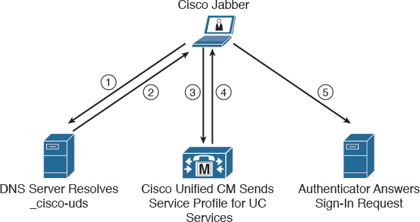
In deployments with CUCM Version 9 and higher, the client can automatically discover services and configuration with the service (SRV) record _cisco-uds:
![]() The client queries the domain name server for SRV records.
The client queries the domain name server for SRV records.
![]() The name server returns the _cisco-uds SRV record.
The name server returns the _cisco-uds SRV record.
![]() The client locates the user’s home cluster. As a result of automatically locating the user’s home cluster, the client can retrieve the device configuration for the user and automatically register telephony services.
The client locates the user’s home cluster. As a result of automatically locating the user’s home cluster, the client can retrieve the device configuration for the user and automatically register telephony services.
Note
In an environment with multiple CUCM clusters, you must configure the Intercluster Lookup Service (ILS). ILS enables the client to find the home cluster of the user.
![]() The client retrieves the user’s service profile. The user’s service profile contains the addresses and settings for UC services and client configuration. The client also determines the authenticator from the service profile.
The client retrieves the user’s service profile. The user’s service profile contains the addresses and settings for UC services and client configuration. The client also determines the authenticator from the service profile.
![]() The client signs the user into the authenticator.
The client signs the user into the authenticator.
SRV Records
You need to deploy multiple DNS SRV records in different locations in your enterprise DNS structure.
You can provision the _cisco-uds SRV record on internal name servers so the client can discover services. This record provides the location of CUCM Version 9 and higher. In an environment with multiple CUCM clusters, you must configure the Intercluster Lookup Service (ILS). ILS enables the client to find the home cluster of the user and discover services.
Note
You should use the fully qualified domain name (FQDN) as the hostname in the SRV record.
The following is an example of the _cisco-uds SRV record:
_cisco-uds._tcp.cisco.com SRV service location:
priority = 10
weight = 10
port = 8443
svr hostname = pub-hq. collab10x.cisco.com
You must provision the _collab-edge SRV record on external name servers as part of the configuration for Cisco TelePresence Video Communication Server (Cisco VCS) Expressway mobile and remote access. You must use the FQDN as the hostname in the SRV record. The client requires the FQDN to use the cookie that the Cisco VCS Expressway server provides.
The following is an example of the _collab-edge SRV record:
collab-edge._tls.cisco.com SRV service location:
priority = 10
weight = 10
port = 8443
svr hostname = vcse.cisco.com
DNS SRV Record Priorities and Weights
This section describes the priorities and weights of the DNS SRV records. The following in an example of DNS SRV entries configured on a DNS server:
_service._protocol.domain TTL class SRV priority weight port target
_cisco-uds._tcp.cisco.com 3600 IN SRV 10 60 8443
cucm1.cisco.com
_cisco-uds._tcp.cisco.com 3600 IN SRV 10 20 8443
cucm2.cisco.com
_cisco-uds._tcp.cisco.com 3600 IN SRV 10 20 8443
cucm3.cisco.com
_cisco-uds._tcp.cisco.com 3600 IN SRV 20 0 8443
cucm4.cisco.com
A DNS SRV entry contains the following parameters:
![]() _service: This parameter is the name of the service and it begins with an underscore (for example, _cisco-uds, _sip, or _ldap).
_service: This parameter is the name of the service and it begins with an underscore (for example, _cisco-uds, _sip, or _ldap).
![]() _protocol: This parameter is the transport protocol of the service and must start with an underscore (for example, _tls, _tcp, or _udp).
_protocol: This parameter is the transport protocol of the service and must start with an underscore (for example, _tls, _tcp, or _udp).
![]() Domain: This parameter is the domain name for which this record is valid (for example, cisco.com).
Domain: This parameter is the domain name for which this record is valid (for example, cisco.com).
![]() TTL: This parameter is the Time to Live (TTL) and defines how long the resolved record can be stored in the cache.
TTL: This parameter is the Time to Live (TTL) and defines how long the resolved record can be stored in the cache.
![]() Class: This parameter is the standard DNS class field. (This parameter is always IN.)
Class: This parameter is the standard DNS class field. (This parameter is always IN.)
![]() Priority: This parameter is the priority of the target host. A lower value indicates a more preferred priority. The range is 0 to 65535.
Priority: This parameter is the priority of the target host. A lower value indicates a more preferred priority. The range is 0 to 65535.
![]() Weight: This parameter is a relative weight between 0 and 65535 for records with the same priority.
Weight: This parameter is a relative weight between 0 and 65535 for records with the same priority.
![]() Port: This parameter is the port on which the service is found.
Port: This parameter is the port on which the service is found.
![]() Target: This parameter is the hostname of the machine providing the service.
Target: This parameter is the hostname of the machine providing the service.
In the example above, for the service _cisco-uds._tcp.cisco.com, are four DNS SRV entries in the enterprise DNS server. The first three records share the same priority level 10. The last DNS SRV entry has a priority of 20. Cisco Jabber will use the first three DNS SRV entries, because the lower priority is more preferred. For entries with the same priority (value 10 in the example) the entry weight is used to determine which entry should be used. Weight values allow an administrator to configure load balancing. In the example above, cucm1.cisco.com will be used 60 percent of the time, and the servers cucm2.cisco.com and cucmm3.cisco.com will each be used 20 percent of the time.
Troubleshoot DNS SRV Entries
This section shows how to verify and troubleshoot configured Cisco User Data Services (Cisco UDS) SVR records.
To ensure that the DNS server is configured correctly and responds with the correct DNS SRV entries, use a client computer and verify that the client uses the same DNS server as the Cisco Jabber client that you are troubleshooting. As an example, on a Microsoft computer, open a command prompt and enter nslookup, as shown in Figure 16-6.
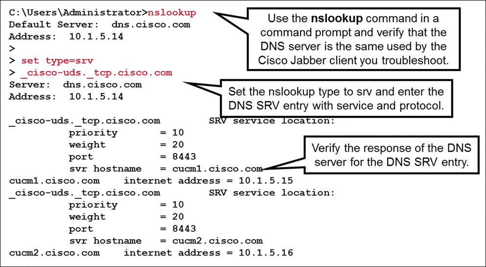
Set the nslookup type to DNS SRV entries with the command set type= srv. Use the previously configured DNS entry and add the service _cisco-uds and the protocol _tcp (for example, _cisco-uds._tcp.cisco.com). The DNS server should now respond with all DNS SRV entries that are configured on the DNS server for this particular service. Verify the response and ensure that the priority, weight, port, and the svr hostname are configured correctly, and that the svr hostname can be resolved to the IP address of the CUCM servers.
Methods of Installation
Cisco Jabber for Windows provides an MSI installation package that can be used in the following ways:
![]() Command line: Specify arguments in a command line window to set installation properties. Choose this option if you plan to install multiple instances.
Command line: Specify arguments in a command line window to set installation properties. Choose this option if you plan to install multiple instances.
![]() Run the MSI manually: Run the MSI manually on the file system of the client workstation and then specify connection properties when you start the client. Choose this option if you plan to install a single instance for testing or evaluation purposes.
Run the MSI manually: Run the MSI manually on the file system of the client workstation and then specify connection properties when you start the client. Choose this option if you plan to install a single instance for testing or evaluation purposes.
![]() Create a custom installer: Open the default installation package, specify the required installation properties, and then save a custom installation package. Choose this option if you plan to distribute an installation package with the same installation properties.
Create a custom installer: Open the default installation package, specify the required installation properties, and then save a custom installation package. Choose this option if you plan to distribute an installation package with the same installation properties.
![]() Deploy with group policy: Install the client on multiple computers in the same domain.
Deploy with group policy: Install the client on multiple computers in the same domain.
The following describes the command syntax to install Cisco Jabber for Windows using the command line with arguments:
msiexec.exe /i CiscoJabberSetup.msi /quiet CLEAR=1
CLEAR=1 deletes any existing bootstrap file, and /quiet specifies a silent installation. The other options are as follows:
![]() PRODUCT_MODE=Phone_Mode sets the client to phone mode.
PRODUCT_MODE=Phone_Mode sets the client to phone mode.
![]() AUTHENTICATOR=CUCM sets CUCM as the authenticator. Other options are CUP and WEBEX.
AUTHENTICATOR=CUCM sets CUCM as the authenticator. Other options are CUP and WEBEX.
![]() TFTP=1.2.3.4 sets 1.2.3.4 as the IP address of the TFTP server that hosts the client configuration. Other options are the hostname and FQDN.
TFTP=1.2.3.4 sets 1.2.3.4 as the IP address of the TFTP server that hosts the client configuration. Other options are the hostname and FQDN.
To deploy Cisco Jabber with group policies, install Cisco Jabber for Windows using the Microsoft Group Policy Management Console (GPMC) on Microsoft Windows Server. To install Cisco Jabber for Windows with Group Policy, all computers or users for which you plan to deploy Cisco Jabber must be in the same domain.
For more information, refer to the Cisco Jabber 10.6 Deployment and Installation Guide http://www.cisco.com/c/en/us/td/docs/voice_ip_comm/jabber/10_6/CJAB_BK_C56DE1AB_00_cisco-jabber-106-deployment-and-installation-guide.html.
Create a Custom Installer with Microsoft Orca
Use Microsoft Orca to create custom installers. Microsoft Orca is available as part of the Microsoft Windows SDK for Windows 7 and .NET Framework 4. You must have the default transform file to modify the installation package with Microsoft Orca. Download the Cisco Jabber administration package from Cisco.com. Copy CiscoJabberProperties.mst from the Cisco Jabber administration package to your file system.
To create a custom installer, use a transform file. Transform files contain installation properties that you apply to the installer. The default transform file lets you specify values for properties when you transform the installer. You should use the default transform file if you are creating one custom installer. Some Microsoft Orca field examples for Jabber include the following:
![]() CLEAR
CLEAR
![]() SERVICES DOMAIN
SERVICES DOMAIN
![]() USE FT GATEWAY
USE FT GATEWAY
![]() LOGIN RESOURCE
LOGIN RESOURCE
![]() CCMCIP
CCMCIP
![]() CTI
CTI
![]() TFTP
TFTP
![]() AUTHENTICATOR
AUTHENTICATOR
![]() CUP ADDRESS
CUP ADDRESS
![]() FORGOT PASSWORD URL
FORGOT PASSWORD URL
![]() TFTP FILE NAME
TFTP FILE NAME
![]() LANGUAGE
LANGUAGE
![]() SSO ORG DOMAIN
SSO ORG DOMAIN
![]() VOICE SERVICES DOMAIN
VOICE SERVICES DOMAIN
![]() EXCLUDED SERVICES
EXCLUDED SERVICES
Summary
This section summarizes the key points that were discussed in this chapter:
![]() On CUCM, configure a SIP trunk and make it the CUP SIP publish trunk. This trunk is used to exchange presence information with the Cisco Unified Communications IM&P server.
On CUCM, configure a SIP trunk and make it the CUP SIP publish trunk. This trunk is used to exchange presence information with the Cisco Unified Communications IM&P server.
![]() The user configuration and many other features are configured in CUCM. Over time, CUCM and Cisco Unified Communications IM&P merged from the administration perspective.
The user configuration and many other features are configured in CUCM. Over time, CUCM and Cisco Unified Communications IM&P merged from the administration perspective.
![]() Cisco jabber discovers the domain and services, so the user only needs to enter the username and password. The _cisco-uds SVR record is used by Cisco Jabber. This SRV record must be set up on the internal DNS server.
Cisco jabber discovers the domain and services, so the user only needs to enter the username and password. The _cisco-uds SVR record is used by Cisco Jabber. This SRV record must be set up on the internal DNS server.
![]() You can customize the MSI installer file for Cisco Jabber to pass along information, such as the domain name, to the installation process.
You can customize the MSI installer file for Cisco Jabber to pass along information, such as the domain name, to the installation process.
This chapter explained how CUCM and Cisco Unified Communications IM&P are integrated. The service discovery and the installation of the Cisco Jabber client were discussed as well.
Review Questions
Answer the following questions, and then see Appendix A, “Answers to Review Questions,” for the answers.
1. Cisco Unified Communications IM&P uses device-based presence to show “On the Phone” in the presence status in Cisco Jabber.
a. True
b. False
2. Which option is not a valid parameter that is required in the SIP trunk security profile when integrating CUCM and Cisco Unified Communications IM&P?
a. Accept Presence Group Notification
b. Accept Out-of-Dialog REFER
c. Accept Unsolicited Notification
d. Accept Replaces Header
3. Which option is not a UC Service that you can specify in the service profile?
a. Mailstore
b. Conferencing
c. Directory
d. IM&P
e. CCMCIP
4. What are the protocols and port used for SIP by default in the SIP trunk security profile? (Choose three.)
a. TCP
b. TLS
c. UDP
d. 5060
e. 5061
f. 5070
5. Which option is a valid DNS service request by Cisco Jabber to discover its services?
a. _cisco_uds._tcp.cisco.com
b. _cisco-uds.tcp.cisco.com
c. _cisco-uds._tls.cisco.com
d. _cisco-uds._tcp.cisco.com