
Chapter 14. Designing and Deploying Cisco Unified IM and Presence
Upon completing this chapter, you will be able to do the following:
![]() Describe native presence in Cisco Unified Communications Manager without Cisco Unified Communications IM and Presence (IM&P) servers
Describe native presence in Cisco Unified Communications Manager without Cisco Unified Communications IM and Presence (IM&P) servers
![]() Describe how the subscribe CSS controls presence watchers
Describe how the subscribe CSS controls presence watchers
![]() Describe how presence groups add more granularity to the presence functionality
Describe how presence groups add more granularity to the presence functionality
![]() Describe the requirements when using Cisco Jabber for presence functionality
Describe the requirements when using Cisco Jabber for presence functionality
![]() Describe how to integrate a Cisco presence solution within a Microsoft environment in an enterprise
Describe how to integrate a Cisco presence solution within a Microsoft environment in an enterprise
![]() Describe the characteristics of the Cisco Unified Communications IM&P OVA templates and the required physical resources
Describe the characteristics of the Cisco Unified Communications IM&P OVA templates and the required physical resources
![]() Describe the Cisco Unified Communications IM&P cluster architecture
Describe the Cisco Unified Communications IM&P cluster architecture
![]() Describe how to deploy Cisco Unified Communications IM&P in different scenarios
Describe how to deploy Cisco Unified Communications IM&P in different scenarios
![]() Describe how Cisco Jabber discovers services to register
Describe how Cisco Jabber discovers services to register
![]() Describe the Cisco Jabber quality of service issues with trust boundaries
Describe the Cisco Jabber quality of service issues with trust boundaries
![]() Describe the different ports that Cisco Jabber uses to communicate
Describe the different ports that Cisco Jabber uses to communicate
![]() Describe how to connect Cisco Unified Communications IM&P clusters within the same domain
Describe how to connect Cisco Unified Communications IM&P clusters within the same domain
![]() Describe how to connect Cisco Unified Communications IM&P clusters that are in different domains
Describe how to connect Cisco Unified Communications IM&P clusters that are in different domains
![]() Describe SIP federations with Microsoft domains
Describe SIP federations with Microsoft domains
![]() Describe the state mappings between Cisco Unified Communications IM&P and Microsoft Skype for Business
Describe the state mappings between Cisco Unified Communications IM&P and Microsoft Skype for Business
![]() Describe the preparation that is necessary to implement a federated presence network
Describe the preparation that is necessary to implement a federated presence network
This chapter describes the Cisco Unified Communications IM and Presence (IM&P) architecture and design. Native presence in Cisco Unified Communications Manager (CUCM) is presented and the different Cisco Unified Communications IM&P approaches are described. Cisco Unified Communications IM&P can be configured to peer with another Cisco Unified Communications IM&P cluster in the same domain or can be federated with Cisco Unified Communications IM&P clusters in a different domain.
Note
The previous name of IM&P was Cisco Unified Presence Server (CUPS) in prior versions of Cisco UC.
CUCM Presence Introduction
This section describes native presence in CUCM without Cisco Unified Communications IM&P servers, as shown in Figure 14-1.
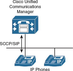
CUCM offers very limited native presence functionality on IP phones. Although a Cisco Unified Communications IM&P server is not required in this simple example, only these native presence features of the CUCM are available:
![]() CUCM speed-dial presence: CUCM administratively supports the ability for a speed dial to have presence capabilities via a BLF speed dial. BLF speed dials work as both a speed dial and a presence indicator.
CUCM speed-dial presence: CUCM administratively supports the ability for a speed dial to have presence capabilities via a BLF speed dial. BLF speed dials work as both a speed dial and a presence indicator.
![]() CUCM call history presence: CUCM administratively supports presence capabilities for call lists and directories on the phone.
CUCM call history presence: CUCM administratively supports presence capabilities for call lists and directories on the phone.
![]() CUCM presence policy: CUCM provides the capability to set policy for users who request presence status.
CUCM presence policy: CUCM provides the capability to set policy for users who request presence status.
CUCM Presence
This section describes the integration of external presence entities into the native presence solution.
All presence requests for users, whether inside or outside a cluster, are processed by CUCM, as shown in Figure 14-2.

A CUCM watcher that sends a presence request will receive a direct response, including the presence status, if the watcher and presence entity are both located within the cluster.
If the presence entity exists outside the cluster, CUCM will query the external presence entity through the Session Initiation Protocol (SIP) trunk. For A watcher that is not in a CUCM cluster, the CUCM can send a presence request off cluster entity by way of a SIP trunk. If the off-cluster entity supports presence, it will respond with the current presence status. If the off-cluster entity does not support presence, it will reject the presence request with a SIP error response.
Skinny Client Control Protocol (SCCP) endpoints can request the presence status of the indicated presence entity by sending SCCP messages to CUCM. If the presence entity resides within the CUCM cluster, CUCM responds to the SCCP line-side presence request by sending SCCP messages to the presence watcher that indicate the status of the presence entity.
CUCM uses the term SIP line to represent endpoints supporting SIP that are directly connected and registered to CUCM, and the term SIP trunk to represent trunks supporting SIP. SIP line-side endpoints acting as presence watchers can send a SIP SUBSCRIBE message to CUCM requesting the presence status of the indicated presence entity.
If the presence entity resides outside the CUCM cluster, CUCM routes a SUBSCRIBE request out on the appropriate SIP trunk, based on the SUBSCRIBE CSS and presence groups. When CUCM receives a SIP NOTIFY response on the trunk that indicates the presence entity status, it responds to the SCCP line-side presence request by sending SCCP messages to the presence watcher indicating the status of the presence entity.
Indicators for Speed-Dial Presence
Table 14-1 describes the native presence indicators on IP phones.

CUCM supports the ability for a speed dial to have presence capabilities via a Busy Lamp Field (BLF) speed dial. BLF speed dials work as both a speed dial and a presence indicator. Only the system administrator can configure a BLF speed dial. A system user is not allowed to configure or modify a BLF speed dial.
The administrator must configure the BLF speed dial with a target directory number that is resolvable to a directory number within the CUCM cluster or an entity accessed by a route pattern at accessed by a SIP trunk destination. The BLF speed-dial indicator is a line-level indicator and not a device-level indicator.
The BLF speed-dial indicators show the real-time state of the monitored phone:
![]() Idle: The user phone is on hook and the user is available.
Idle: The user phone is on hook and the user is available.
![]() Busy: The user phone is off hook and the user is not available.
Busy: The user phone is off hook and the user is not available.
![]() Unknown: The real-time state cannot be determined. The phone might be disconnected, the users are not in the same presence group, or the users are not allowed to see the presence status.
Unknown: The real-time state cannot be determined. The phone might be disconnected, the users are not in the same presence group, or the users are not allowed to see the presence status.
CUCM Call Presence
Call list presence capabilities are controlled via the BLF for the Call Lists enterprise parameter within CUCM Administration. The BLF for the Call Lists enterprise parameter impacts all pages that use the phone Directories button and it is set on a global basis, as shown in Figure 14-3.

CUCM Subscribe CSS
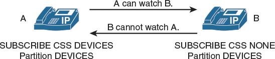
Figure 14-4 describes how the subscribe CSS controls presence watchers.
CUCM provides the capability to set policy for users who request presence status:
![]() Configure a CSS to route SIP SUBSCRIBE messages for presence status.
Configure a CSS to route SIP SUBSCRIBE messages for presence status.
![]() Configure presence groups with which watchers can be associated, that specify rules for viewing the presence status of presence entities that are associated with another group.
Configure presence groups with which watchers can be associated, that specify rules for viewing the presence status of presence entities that are associated with another group.
The first aspect of presence policies for CUCM is the subscribe CSS. CUCM uses the subscribe CSS to determine how to route presence requests. Presence requests are SUBSCRIBE messages with the Event field set to Presence. These messages are sent from the watcher, which can be a phone or a trunk. The subscribe CSS is associated with the watcher and lists the partitions that the watcher is allowed to see. This mechanism provides an additional level of granularity for the presence SUBSCRIBE requests to be routed independently from the normal call-processing CSS.
With the subscribe CSS set to <None>, BLF speed dial and call list presence status does not work (if no directory number or route pattern is associated with the <None> partition) and the subscription message is rejected as “user unknown.” When a valid subscribe CSS is specified, the indicators work and the SUBSCRIBE messages are accepted and routed properly.
CUCM Presence Groups
Figure 14-5 illustrates how presence groups add more granularity to the presence functionality.

Devices, directory numbers, and users can be assigned to a presence group, and by default, all users are assigned to the same standard presence group. By default, if the subscribe calling search space (CSS) permits, all watchers can watch all other entities.
A presence group controls the destinations that a watcher can monitor, based on the association of a user with a defined presence group; for example, employees watching managers is disallowed, but managers watching employees is allowed.
When multiple presence groups are defined, as shown in the picture, the Inter-Presence Group Subscribe Policy service parameter is applied. If one group has a relationship to another group via the Use System Default setting, rather than being allowed or disallowed, the value of this service parameter will take effect. If the Inter-Presence Group Subscribe Policy service parameter is set to Disallowed, CUCM will block the request even if the subscribe CSS allows it.
Note
The Inter-Presence Group Subscribe Policy service parameter applies only for presence status with call lists and is not used for BLF speed dials.
Observe the following guidelines when configuring presence within CUCM:
![]() Define a presence policy for presence users.
Define a presence policy for presence users.
![]() Use subscribe CSSs to control the routing of a watcher presence-based SIP SUBSCRIBE message to the correct destinations.
Use subscribe CSSs to control the routing of a watcher presence-based SIP SUBSCRIBE message to the correct destinations.
![]() Use presence groups to define sets of similar users and to define whether presence status updates of other user groups are allowed or disallowed.
Use presence groups to define sets of similar users and to define whether presence status updates of other user groups are allowed or disallowed.
![]() Call list presence capabilities are enabled on a global basis. The user status can be secured by using a presence policy.
Call list presence capabilities are enabled on a global basis. The user status can be secured by using a presence policy.
![]() BLF speed dials are administratively controlled and are not impacted by the presence policy configuration.
BLF speed dials are administratively controlled and are not impacted by the presence policy configuration.
Cisco Unified Communications IM&P Introduction
Figure 14-6 illustrates the components when using Cisco Jabber for presence functionality.

Integrating Cisco WebEx Meetings Server, Cisco Unity Connection, and other applications into the presence network offers a feature-rich communications environment with the Cisco Jabber client application as the single interface for voice and video calls, voice-mail playback, web conferencing, and integrated directories.
The following are available features in this deployment:
![]() Real-time availability: This feature provides real-time availability of other Cisco Jabber users.
Real-time availability: This feature provides real-time availability of other Cisco Jabber users.
![]() Contact list: This feature allows users to search the corporate directory from one easy-to-use interface to locate contacts quickly. Simply click to call.
Contact list: This feature allows users to search the corporate directory from one easy-to-use interface to locate contacts quickly. Simply click to call.
![]() Media escalation: This feature provides the ability to add communication methods during a session; for example, add video to an existing audio session, or add web conferencing to an existing audio or video session.
Media escalation: This feature provides the ability to add communication methods during a session; for example, add video to an existing audio session, or add web conferencing to an existing audio or video session.
![]() Click-to-call: This feature provides the ability to dial from the contact list by using the integrated softphone or an associated IP phone.
Click-to-call: This feature provides the ability to dial from the contact list by using the integrated softphone or an associated IP phone.
![]() Integrated voice and video calling: This feature provides the ability to exchange ideas face to face with a coordinated video display on the PC screen and audio conversation with the softphone. Users can place video calls to other users.
Integrated voice and video calling: This feature provides the ability to exchange ideas face to face with a coordinated video display on the PC screen and audio conversation with the softphone. Users can place video calls to other users.
![]() IP phone association: This feature allows users to use Cisco Jabber to control an IP phone and make or receive calls.
IP phone association: This feature allows users to use Cisco Jabber to control an IP phone and make or receive calls.
![]() Conferencing: This feature allows users to create multiparty voice or video conferencing sessions by simply merging conversation sessions by using the Cisco Jabber intuitive interface.
Conferencing: This feature allows users to create multiparty voice or video conferencing sessions by simply merging conversation sessions by using the Cisco Jabber intuitive interface.
![]() Web conferencing: This feature allows users to launch a web conferencing session immediately to share content, such as a presentation, with others.
Web conferencing: This feature allows users to launch a web conferencing session immediately to share content, such as a presentation, with others.
![]() Voice messages: This feature allows users to access Cisco Unity Connection voice-mail messages—view, play back, sort, and delete messages—all from the same client application.
Voice messages: This feature allows users to access Cisco Unity Connection voice-mail messages—view, play back, sort, and delete messages—all from the same client application.
Microsoft Integration
Figure 14-7 illustrates how to integrate a Cisco presence solution within a Microsoft environment in an enterprise.
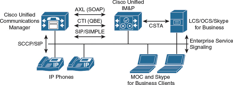
Cisco Unified Communications IM&P implements a Computer-Supported Telephony Application to Computer Telephony Integration (CSTA-to-CTI) bridge to integrate with Microsoft Office Communications Server (OCS) and Skype for Business interfaces. Cisco Unified Communications IM&P includes the following CTI gateway functionalities:
![]() CSTA over SIP interface to Microsoft Skype for Business and OCS server is available.
CSTA over SIP interface to Microsoft Skype for Business and OCS server is available.
![]() A CTI interface to CUCM is available.
A CTI interface to CUCM is available.
![]() A linkage of the older Microsoft Office Communicator (MOC) and the current Microsoft Skype for Business client and CUCM endpoints for a specific user is realized, which supports monitoring of CUCM endpoint activity via Microsoft clients. Support for call establishment and call modification for CUCM endpoints via Microsoft clients is also included.
A linkage of the older Microsoft Office Communicator (MOC) and the current Microsoft Skype for Business client and CUCM endpoints for a specific user is realized, which supports monitoring of CUCM endpoint activity via Microsoft clients. Support for call establishment and call modification for CUCM endpoints via Microsoft clients is also included.
![]() The functionality provides click to dial, phone hook status reporting, and general phone control directly from the Microsoft client.
The functionality provides click to dial, phone hook status reporting, and general phone control directly from the Microsoft client.
OVA Template for Cisco Unified Communications IM&P
Table 14-2 presents the available VM overlays for Cisco Unified Communications IM&P installations.
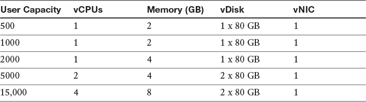
The 500-user OVA template is the minimum VM configuration for use with the Cisco Hosted Collaboration Solution. The 1000-user OVA template is only supported for Cisco Business Edition 6000.
Another important factor is the number of presence or IM users. When using only IM, without presence, higher user counts are supported per server and cluster:
![]() 500 full UC users, 1000 IM-only users, 6 single nodes, or subclusters
500 full UC users, 1000 IM-only users, 6 single nodes, or subclusters
![]() 1000 full UC users, 2000 IM-only users
1000 full UC users, 2000 IM-only users
![]() 2000 full UC users per node, 2000 IM-only users, 3 single nodes, or subclusters
2000 full UC users per node, 2000 IM-only users, 3 single nodes, or subclusters
![]() 5000 full UC users, 12,500 IM-only users, 6 single nodes, or subclusters
5000 full UC users, 12,500 IM-only users, 6 single nodes, or subclusters
![]() 15,000 full UC users, 25,000 IM-only users, 6 single nodes, or subclusters
15,000 full UC users, 25,000 IM-only users, 6 single nodes, or subclusters
Note
These templates may be adjusted and optimized with new releases of Cisco Unified Communications applications or VMware vSphere ESXi and can be found at http://docwiki.cisco.com/wiki/Virtualization_for_Unified_CM_IM_and_Presence.
IM&P Service maximum capacities per cluster are as follows:
![]() Cisco Unified Communications mode: In this mode, IM&P service integrates into a full Cisco Collaboration Systems environment to provide an enterprise-class IM&P solution in conjunction with the full suite of Cisco Collaboration Systems services, including voice and video. In this mode, IM&P service supports Cisco Collaboration Systems clients, such as the Cisco Jabber platform, and Cisco Jabber SDK, as well as third-party Extensible Messaging and Presence Protocol (XMPP) standard-based clients. When operating in Cisco Unified Communications mode, IM&P Service scales up to a maximum of 45,000 users in a multinode CUCM cluster environment.
Cisco Unified Communications mode: In this mode, IM&P service integrates into a full Cisco Collaboration Systems environment to provide an enterprise-class IM&P solution in conjunction with the full suite of Cisco Collaboration Systems services, including voice and video. In this mode, IM&P service supports Cisco Collaboration Systems clients, such as the Cisco Jabber platform, and Cisco Jabber SDK, as well as third-party Extensible Messaging and Presence Protocol (XMPP) standard-based clients. When operating in Cisco Unified Communications mode, IM&P Service scales up to a maximum of 45,000 users in a multinode CUCM cluster environment.
![]() IM-only user mode: IM&P Service provides an enterprise-class IM&P solution for enterprise users who are not using CUCM for call control. In IM-only user mode, IM&P Service supports Cisco Collaboration Systems clients such as the Cisco Jabber client, and Cisco Jabber SDK for all enterprise-class IM&P services. IM&P Service also supports the ability for third-party XMPP standard-based clients to interface with CUCM for IM&P services. When operating in Cisco IM-only user mode, IM&P Service scales up to a maximum of 75,000 users in a multinode cluster environment. Users deployed as part of the Jabber for Everyone offer without voice and video services operate in IM-only user mode.
IM-only user mode: IM&P Service provides an enterprise-class IM&P solution for enterprise users who are not using CUCM for call control. In IM-only user mode, IM&P Service supports Cisco Collaboration Systems clients such as the Cisco Jabber client, and Cisco Jabber SDK for all enterprise-class IM&P services. IM&P Service also supports the ability for third-party XMPP standard-based clients to interface with CUCM for IM&P services. When operating in Cisco IM-only user mode, IM&P Service scales up to a maximum of 75,000 users in a multinode cluster environment. Users deployed as part of the Jabber for Everyone offer without voice and video services operate in IM-only user mode.
![]() Microsoft Skype for Business interoperability mode (or Microsoft Remote Call Control): In this mode, IM&P Service allows Microsoft Skype for Business users on a PC to interoperate with Cisco Unified IP phones on CUCM by providing click-to-dial and associated phone monitoring capabilities. Interoperability is made available by activating Microsoft Skype for Business interoperability mode in IM&P Service and configuring Microsoft Skype for Business users. When operating in this mode, IM&P Service scales up to 40,000 Microsoft Office Communicator users per CUCM cluster.
Microsoft Skype for Business interoperability mode (or Microsoft Remote Call Control): In this mode, IM&P Service allows Microsoft Skype for Business users on a PC to interoperate with Cisco Unified IP phones on CUCM by providing click-to-dial and associated phone monitoring capabilities. Interoperability is made available by activating Microsoft Skype for Business interoperability mode in IM&P Service and configuring Microsoft Skype for Business users. When operating in this mode, IM&P Service scales up to 40,000 Microsoft Office Communicator users per CUCM cluster.
Cisco Unified Communications IM&P Cluster
Figure 14-8 illustrates the Cisco Unified Communications IM&P cluster architecture maximum option of up to six servers per cluster.
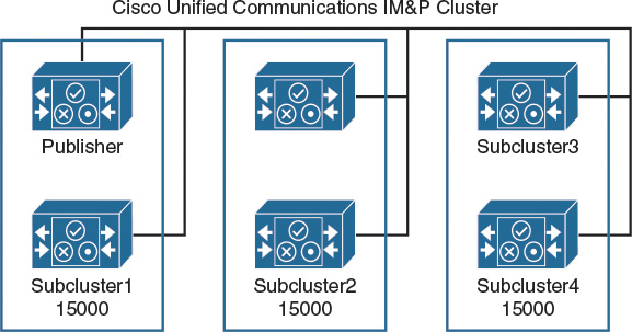
A cluster can be formed to scale Cisco Unified Communications IM&P to support up to 45,000 licensed presence users. The Cisco Unified Communications IM&P server uses the same virtualization approach that is used by CUCM or Cisco Unity Connection.
Cisco Unified Communications IM&P consists of up to six servers, including one server that is designated as a publisher. Cisco Unified Communications IM&P utilizes the same architectural concepts as the CUCM publisher and subscriber. Within a Cisco Unified Communications IM&P cluster, individual servers can be grouped to form a subcluster, and the subcluster can have at most two servers that are associated with it.
The figure shows the topology for a Cisco Unified Communications IM&P cluster. The Cisco Unified Communications IM&P cluster can also have mixed subclusters, where one subcluster is configured with two servers while other subclusters contain a single server. The Cisco Unified Communications IM&P servers form their own cluster even if they are integrated as subscribers in the CUCM cluster.
CUCM Deployment Options
This section describes how to deploy Cisco Unified Communications IM&P in different scenarios. Figure 14-9 illustrates CUCM and IM&P in different locations.
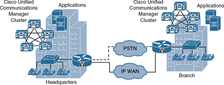
Cisco IM&P is supported with all CUCM deployment models. However, Cisco recommends locating the Cisco IM&P publisher in the same physical datacenter as the CUCM publisher due to the initial user database synchronization. All on-premises Cisco IM&P servers should be physically located in the same datacenter within the Cisco IM&P cluster, with the exception of geographic datacenter redundancy and clustering over the WAN.
A CUCM cluster can only connect to a single Cisco Unified Communications IM&P cluster. When you have a distributed CUCM deployment with two or more CUCM clusters, you also need two or more Cisco Unified Communications IM&P clusters per site. These Cisco Unified Communications IM&P servers can be connected using intercluster peers, when the clusters are in the same domain. If the Cisco Unified Communications IM&P clusters use different domains, a federation must be set up.
Service Discovery
When the Cisco Jabber client is opened the first time after a standard installation, you are asked to enter your e-mail address, as shown on the left of Figure 14-10.
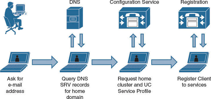
Based on the domain in your e-mail address, Cisco Jabber asks the DNS server for server records for _cisco-uds._tcp.example.com, as shown in the figure. The answer includes the IP address of a CUCM cluster server. Cisco Jabber contacts the CUCM server and requests the home cluster and service profile information that is required to reach the other application servers. Additional information is received via the jabber-config.xml file from the TFTP server in the CUCM cluster.
Quality of Service
This section describes the Cisco Jabber quality of service issues with trust boundaries.
The Cisco Jabber client marks call-signaling traffic with a differentiated services code point (DSCP) value of 24, or a PHB value of CS3, and it marks RTP media traffic with a DSCP value of 46 (PHB value of EF). Video traffic will be marked with a per-hop behavior (PHB) value of AF41 (DSCP value of 34), as illustrated in Table 14-3.

Typically, networks are configured to strip DSCP markings from computer traffic. Therefore, if the administrator wants Cisco Jabber traffic to be marked, the administrator must configure switches and routers to preserve DSCP markings for packets originating from the Jabber client application.
Cisco Jabber Port Usage
Table 14-4 describes the different ports that Cisco Jabber uses to communicate.
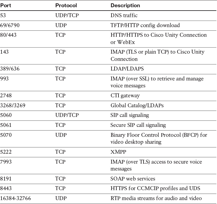
As shown in the table, Cisco Jabber uses a number of protocols for communication. In addition, these protocols may be used and are listed here for your reference:
![]() Port 7080: Protocol TCP (HTTPS); used for Cisco Unity Connection for notifications of voice messages (new message, message update, and message deletion)
Port 7080: Protocol TCP (HTTPS); used for Cisco Unity Connection for notifications of voice messages (new message, message update, and message deletion)
![]() Port 37200: Protocol SOCKS5 Bytestreams; used for peer-to-peer file transfers. In on-premises deployments, the client also uses this port to send screen captures.
Port 37200: Protocol SOCKS5 Bytestreams; used for peer-to-peer file transfers. In on-premises deployments, the client also uses this port to send screen captures.
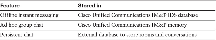
Enterprise Instant Messaging
This section describes enterprise instant messaging (EIM).
Cisco Unified Communications IM&P incorporates the supported EIM features of the Cisco Jabber Extensible Communications Platform (XCP), while allowing for modifications to enhance support for the multidevice user experience. Text conferencing, sometimes referred to as multiuser chat, is defined as ad hoc group chat. Persistent group chat is supported as part of the Jabber XCP feature set. In addition, offline IM (storing instant messages for users who are currently offline) is also supported as part of the Jabber XCP feature set. Cisco Unified Communications IM&P manages storage for each of these IM features in different locations, as shown in Table 14-5.
Note
The supported external databases are PostgreSQL (see http://www.postgresql.org/) and Oracle (see http://www.oracle.com).
If persistent chat is enabled, ad hoc rooms are stored on the external PostgreSQL database for the duration of the ad hoc chat. This procedure allows a room owner to escalate an ad hoc chat to a persistent chat; otherwise, these ad hoc chats are purged from PostgreSQL at the end of the chat. If persistent chat is disabled, ad hoc chats are stored in volatile memory for the duration of the chat.
Multicluster Deployment
Figure 14-11 illustrates how to connect Cisco Unified Communications IM&P clusters within the same domain.
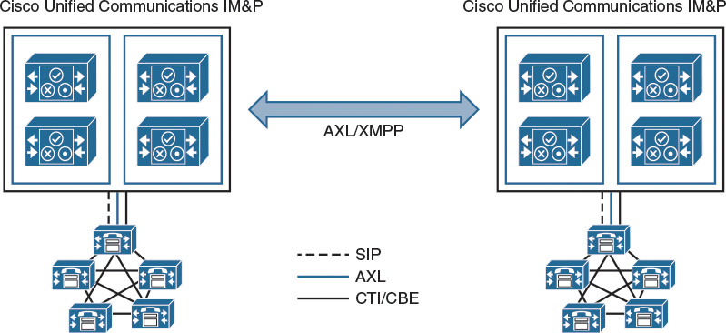
To extend presence and IM capability and functionality, these standalone clusters can be configured for peer relationships, thus enabling communication between clusters within the same domain. The figure represents the peer relationship between Cisco Unified Communications IM&P clusters when multiple clusters or sites are interconnected. This functionality provides the ability for users in one cluster to communicate and subscribe to the presence of users in a different cluster within the same domain.
To create a fully meshed presence topology, each Cisco Unified Communications IM&P cluster requires a separate peer relationship with each of the other Cisco Unified Communications IM&P clusters within the same domain. The address that is configured in this intercluster peer could be a DNS server FQDN that resolves to the remote Cisco Unified Communications IM&P cluster servers. The address could also simply be the IP address of the Cisco Unified Communications IM&P cluster servers.
The interface between Cisco Unified Communications IM&P clusters is twofold, an Administrative XML - Simple Object Access Protocol (AXL-SOAP) interface, and (SIP or XMPP). The AXL-SOAP interface manages the synchronization of user information for home cluster association, but it is not a complete user synchronization. The signaling protocol interface (SIP or XMPP) manages the subscription and notification traffic, and it rewrites the host portion of the URI before forwarding if the user is on a remote Cisco Unified Communications IM&P cluster within the same domain.
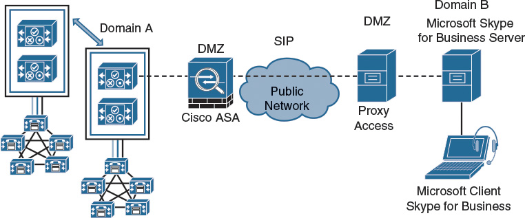
Federated Deployment
This section describes how to connect Cisco Unified Communications IM&P clusters that are in different domains.
Interdomain federation parameters:
![]() Two different DNS domains
Two different DNS domains
![]() Cisco Adaptive Security Appliance (ASA) appliance in demilitarized zone (DMZ)
Cisco Adaptive Security Appliance (ASA) appliance in demilitarized zone (DMZ)
Cisco Unified Communications IM&P allows for business-to-business communications by enabling interdomain federation, which provides the ability to share presence and IM communications between different domains.
Federation is a term that describes data servers in different domains that can securely connect to one another, as shown in Figure 14-12.

Interdomain federation requires that two explicit DNS domains are configured, as well as a security appliance (Cisco ASA) in the DMZ to terminate federated connections with the enterprise.
Figure 14-12 shows a basic interdomain federation deployment between two different domains, indicated by Domain A and Domain B. The Cisco Adaptive Security Appliance in the DMZ is used as a point of demarcation into the enterprise. XMPP traffic is passed through, whereas SIP traffic is inspected. All federated incoming and outgoing traffic is routed through the Cisco Unified Communications IM&P server that is enabled as a federation node, and is routed internally to the appropriate server in the cluster where the user resides. For multicluster deployments, intercluster peers propagate the traffic to the appropriate home cluster within the domain. Multiple nodes can be enabled as federation nodes within large enterprise deployments, where each request is routed based on a round-robin implementation of the data that is returned from the DNS server lookup.
Microsoft Skype for Business Federation
Figure 14-13 illustrates Cisco SIP federations with one or more Microsoft domains.
Cisco Unified Communications IM&P provides interdomain federation with Microsoft Skype for Business and the older Microsoft OCS, Microsoft Live Communications Server (LCS) to provide basic presence (available, away, busy, offline), and point-to-point IM.
Cisco Unified Communications IM&P must publish a DNS server record (SIP, XMPP, and each text conferencing node) for the domain to allow other domains to discover the Cisco Unified Communications IM&P servers through the DNS server records. With a Microsoft deployment, this procedure is required because Cisco Unified Communications IM&P is configured as a public IM provider on the access edge server. If the Cisco Unified Communications IM&P server cannot discover the Microsoft domain using DNS server records, the administrator must configure a static route on Cisco Unified Communications IM&P for the external domain.
The Cisco Unified Communications IM&P federation deployment can be configured with redundancy using a load balancer between the Cisco Adaptive Security Appliance and the Cisco Unified Communications IM&P server. Redundancy can also be achieved with a redundant Cisco Adaptive Security Appliance configuration.
In an intercluster and a multinode cluster Cisco Unified Communications IM&P deployment, when a foreign Microsoft domain initiates a new session, the Cisco Adaptive Security Appliance routes all messages to a Cisco Unified Communications IM&P server that is designated for routing purposes. If the Cisco Unified Communications IM&P routing server does not host the recipient user, it routes the message via intercluster communication to the appropriate Cisco Unified Communications IM&P server within the cluster. The system routes all responses that are associated with this request through the routing Cisco Unified Communications IM&P server.
Mapping of Presence Status
As Cisco’s and Microsoft’s products are developed separately by the different companies, in a federation between Cisco and Microsoft presence, not all presence fields have the same meaning. Table 14-6 shows a comparison between Cisco and Microsoft presence.
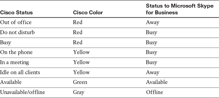
Rich presence capability (on the phone, in a meeting, on vacation, and so on), as well as advanced IM features, are not supported in an interdomain federation.
Federation Preparation
Additional preparation is required before implementing a federated deployment including routing, allocating public IP addresses, providing DNS records, and certificates. The following list gives you a quick overview of the tasks you must consider when building a federation on Cisco Unified Communications IM&P. Depending on the company, many departments may be involved when deploying presence federations.
![]() Routing configuration
Routing configuration
![]() Cisco Unified Communications IM&P to Cisco ASA appliance to foreign domain
Cisco Unified Communications IM&P to Cisco ASA appliance to foreign domain
![]() Access lists and firewalls
Access lists and firewalls
![]() Public IP address
Public IP address
![]() Outside interface of the Cisco ASA appliance
Outside interface of the Cisco ASA appliance
![]() Use Network Address Translation (NAT) or Port Address Translation (PAT)
Use Network Address Translation (NAT) or Port Address Translation (PAT)
![]() DNS configuration
DNS configuration
![]() Cisco Unified Communications IM&P must publish a DNS server record
Cisco Unified Communications IM&P must publish a DNS server record
![]() Publish the DNS server record _xmpp-server
Publish the DNS server record _xmpp-server
![]() Certificate authority server
Certificate authority server
![]() When using TLS, upload root certificate to Cisco Unified Communications IM&P server.
When using TLS, upload root certificate to Cisco Unified Communications IM&P server.
![]() CUCM supports native presence for BLF or call history. Cisco Unified Communications IM&P is required for Cisco Jabber and presence functionality.
CUCM supports native presence for BLF or call history. Cisco Unified Communications IM&P is required for Cisco Jabber and presence functionality.
![]() Cisco Unified Communications IM&P can be federated with other domains via XMPP (for example, with Google Talk or via SIP with Microsoft Skype for Business).
Cisco Unified Communications IM&P can be federated with other domains via XMPP (for example, with Google Talk or via SIP with Microsoft Skype for Business).
![]() Persistent chat, message archiving, and compliance require external databases (for example, PostgreSQL).
Persistent chat, message archiving, and compliance require external databases (for example, PostgreSQL).
![]() When designing Cisco Unified Communications IM&P, the limit is 45,000 users enabled for presence per cluster. A CUCM cluster can only connect to one Cisco Unified Communications IM&P cluster.
When designing Cisco Unified Communications IM&P, the limit is 45,000 users enabled for presence per cluster. A CUCM cluster can only connect to one Cisco Unified Communications IM&P cluster.
This chapter explained how to design and deploy a Cisco Unified Communications IM&P solution in different CUCM scenarios.
Review Questions
Answer the following questions, and then see Appendix A, “Answers to Review Questions,” for the answers.
1. Native presence in CUCM requires a Cisco Unified Communications IM&P server to function properly.
a. True
b. False
2. Which protocol is used between Cisco Unified Communications IM&P and Microsoft Skype for Business when integrating in an enterprise network?
a. AXL
b. CSTA
c. SIP
d. XMPP
3. Which two options identify the maximum number of presence users and the maximum number of IM-only users that are permitted in a Cisco Unified Communications IM&P cluster? (Choose two)
a. 40,000 presence users
b. 45,000 presence users
c. 75,000 presence users
e. 75,000 IM-only users
f. 80,000 IM-only users
4. How many servers can be in a Cisco Unified Communications IM&P cluster?
a. 2
b. 4
c. 5
d. 6
e. 8
5. Which port number must be opened in a firewall to allow Cisco Jabber to discover services?
a. 53 DNS
b. 69 TFTP
c. 3268 Global Catalog
d. 5060 SIP
e. 5222 XMPP