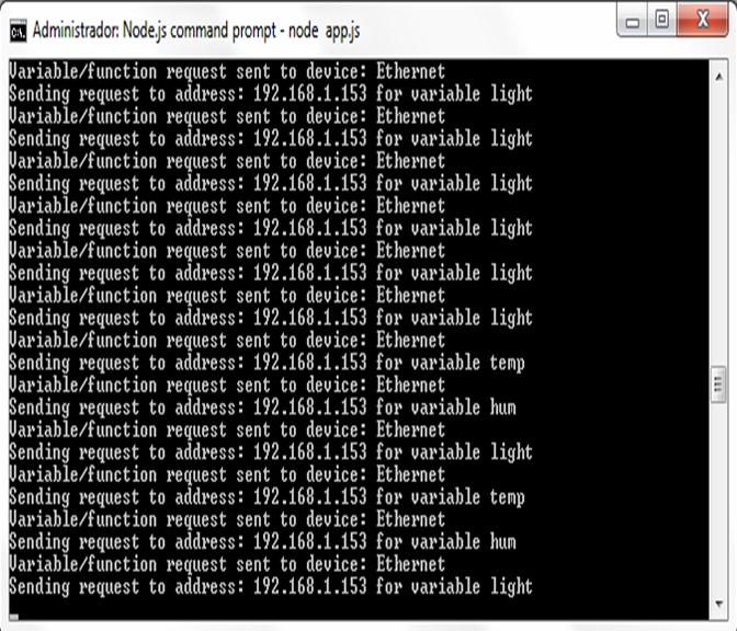
In the preceding section, we showed how to monitor our Arduino via Wi-Fi using the CC3000 module; now we will use another important module: Ethernet Shield. The hardware connection of the part is similar to the following image:
You can now either copy the code inside a file called Monitor_Ethernet.ino, or just get the complete code from the folder for this project; you need to use the Arduino IDE.
The following are the libraries included in the program:
#include <SPI.h>
#include <Ethernet.h>
#include <aREST.h>
#include <avr/wdt.h>
Include the library for the DHT11 sensor:
#include "DHT.h"
We define the pins for the temperature and humidity sensor:
#define DHTPIN 7
#define DHTTYPE DHT11
We have the instance of the sensor:
DHT dht(DHTPIN, DHTTYPE);
We register the MAC address for the device:
byte mac[] = { 0x90, 0xA2, 0xDA, 0x0E, 0xFE, 0x40 };
IPAddress ip(192,168,1,153);
EthernetServer server(80);
We now create an instance of the aREST API:
aREST rest = aREST();
We publish the variables that will be monitored:
int temp;
int hum;
int light;
We now configure serial communication and start the instance of the sensor:
void setup(void)
{
  // Start Serial
  Serial.begin(115200);
  dht.begin();
We start the variables to publish:
  rest.variable("light",&light);
  rest.variable("temp",&temp);
  rest.variable("hum",&hum);
It is very important to give the ID and the name of the device that we are using:
  rest.set_id("008");
  rest.set_name("Ethernet");
We begin the Ethernet connection:
if (Ethernet.begin(mac) == 0) {
    Serial.println("Failed to configure Ethernet using DHCP");
    Ethernet.begin(mac, ip);
  }
We display the IP address on the serial monitor:
  server.begin();
  Serial.print("server is at ");
  Serial.println(Ethernet.localIP());
  wdt_enable(WDTO_4S);
}
We read the temperature and humidity sensor:
void loop() {

  temp = (float)dht.readTemperature();
  hum = (float)dht.readHumidity();
We measure the light level of the sensor:
  float sensor_reading = analogRead(A0);
  light = (sensor_reading/1024*100);
We listen for the incoming clients that will be connected:
  EthernetClient client = server.available();
  rest.handle(client);
  wdt_reset();
}
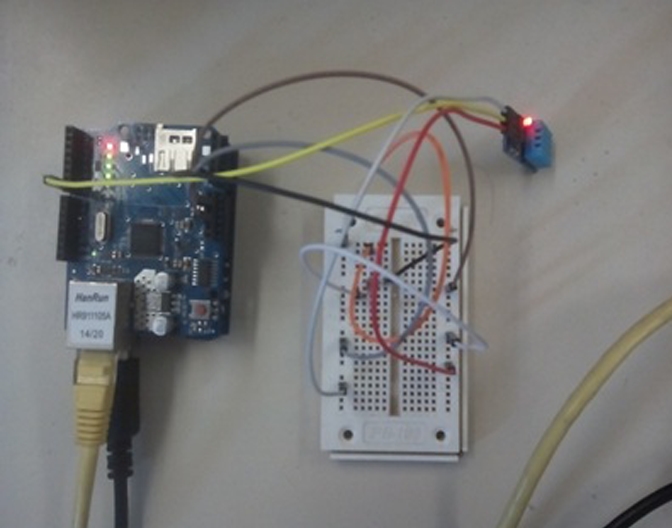
Now that we have finished the configurations, we open a web browser and type the IP address of your Arduino Ethernet shield: http://192.168.1.153. If everything goes perfectly it will display the following screen with the JSON response from the board:
The preceding screenshot shows the results of the JSON request.
In this section, we will explain the code for configuring the devices that we can control from a web page.
We installed the express package in the previous section; if you have any difficulty, just open a terminal and type the following:
npm install express
We define the node express and create the app:
var express = require('express'),
var app = express();
We then define the port to listen:
var port = 3000;
We define the instance of Jade application, using the view engine:
app.set('view engine', 'jade'),
We configure the public folder:
app.use(express.static(__dirname + '/public'));
We now define the devices to monitor:
var rest = require("arest")(app);
rest.addDevice('http','192.168.1.153'),
We serve the application:
app.get('/', function(req, res){
res.render('interface'),
});
We start the server and send the message when the device is connected:
app.listen(port);
console.log("Listening on port " + port);
Open your terminal in MS-DOS and execute app.js in your Node.js server
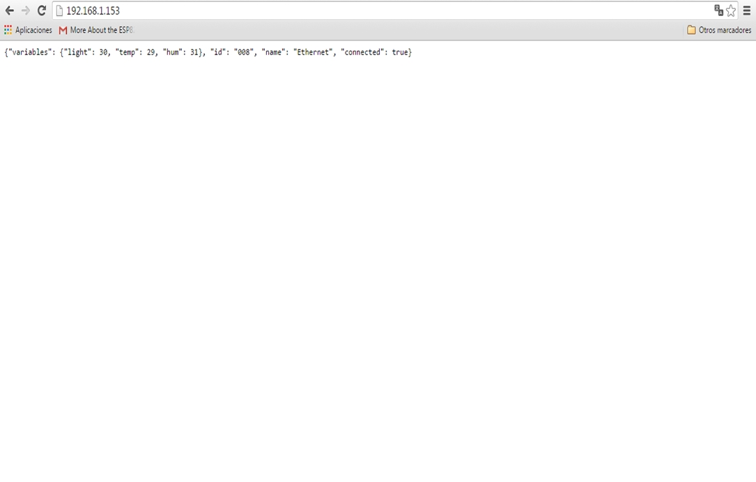
To test the application, open your web browser and type http://localhost:3000; if a screen like the following, congratulations appears, you just configured your server properly:
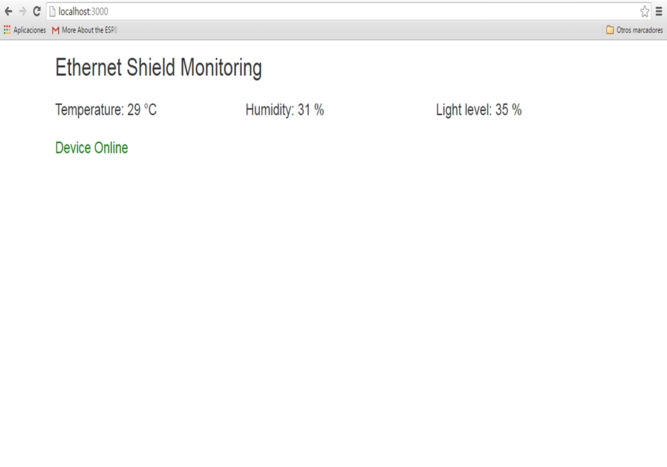
Here we have the screen where we see the execution of app.js in the Node.js server: