
Chapter 16
UV Mapping and Editing
Preparing Your Model and Creating UV Maps
Introduction to UV Mapping
And now we move on to UV mapping. If there were such a thing as a Holy Grail of texturing that was greatly sought after by artists, then UV mapping would probably be it. The fact is that all too often there seems to be this shroud of mystery surrounding the use of UV mapping, which makes it appear as a scary, difficult process that requires some kind of genius to master.
The truth is that UV mapping is actually very simple. However, it is an occasionally painful process that can, more often than not, take ages to complete. This is not because it is a very complicated process, but simply because of the nature of editing the actual maps, which is a pretty tedious and usually rather lengthy process.
However, do not despair at the thought of such tedium. Once you understand how the process works, it can actually be strangely enjoyable, as it is a refreshing break from the often mind-bending techniques involved in other areas of the 3D creation process. I always feel a tremendous sense of satisfaction when looking at the results of hours of tweaking a UV map and seeing that it is perfect!
Let’s begin to work our way through this shroud of awe and wonder that surrounds the subject.
UV mapping is, in essence, simply a way of converting the topographical information of your model into a flat 2D layout that is then used as a template for painting textures. UV mapping is just another method of placing textures onto your models, except that in this case, a little more work is required in Modeler.
The U and V refer to coordinates in 2D space, just as the letters X, Y, and Z refer to coordinates in the 3D space that you are used to working with when modeling. Basically, you could say that when you flatten X, Y, and Z, you get U and V. So they are not letters that refer to some secret code that could unlock some deep mystery; they are just simple coordinates. The u-axis is the horizontal one, and the v-axis is vertical.
Any point within the UV map has both U and V values that you can adjust using the UV tools within Modeler.
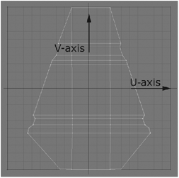
Figure 16-1
You make a UV map by selecting the model you wish to unwrap, or a section of it, and clicking on the New UV Map button under the Texture section on the Map tab in Modeler. When creating a UV map, you are presented with a number of options, discussed later in this chapter.
NOTE: You cannot make or edit UV maps in Layout. All mapping tools are found in Modeler.
The UV Editor
Before we begin unwrapping and editing UV maps, let’s take a look at the LightWave Modeler UV Texture Editor.
Each Modeler viewport has three buttons at the top-left corner, two of which are drop-down menus with several view mode options. To open the UV Texture Editor, all you have to do is select the UV Texture option under the viewport’s first drop-down menu, the same one you use to select the many different view modes for that particular viewport.

Figure 16-2
In the second drop-down menu, you can select a background image currently loaded in the Image Editor. If you don’t have any images loaded, you have the option to load one from disk. I usually start with a generic checker-board grid to edit my UV layout, constantly checking it for correct placement, overlapping, and distortion.
The next button is the Free Move button. This handy option allows you to detach the currently selected faces from the laid out mesh and move them to a different location in the UV space, like an instant unweld operation! This is extremely useful since it will decrease the amount of unwelding you do during the UV creation process. I’ll discuss the Free Move option in depth in Chapter 17 in the “Understanding Discontinuous UV Maps” section.
In the UV Texture viewport you’ll see a UV grid. This is where you will lay out your, well, you guessed it, UVs! It is recommended (especially for organic models) that you keep your layout inside this grid; any parts of your UV layout falling outside of this grid will have the texture tiled. Tiling UVs are more often used in hard models, such as an asphalt road or a concrete wall. Keep in mind that your texture has to be seamless; otherwise, you’ll find seams when the texture tiles over your object. (This might be obvious to some, but I thought I should mention it for those who are new to LightWave and texture mapping in general.)
NOTE: The Free Move function has been available in LightWave since version 8.2.
Planning Your UV Maps
One of the most important things about using UV maps is that you need to plan them properly. If you have ever tried to unwrap an entire character model (as many people often try to do) and seen the resulting chaos that appears in the UV map viewport, you will know that there is a certain trick to getting a decent result from the command.
The trick lies in planning where and how you will unwrap the model. Obviously, some types of UV maps are better suited to certain shapes than others. You have to figure out which ones are suited to your needs, and execute them as such.
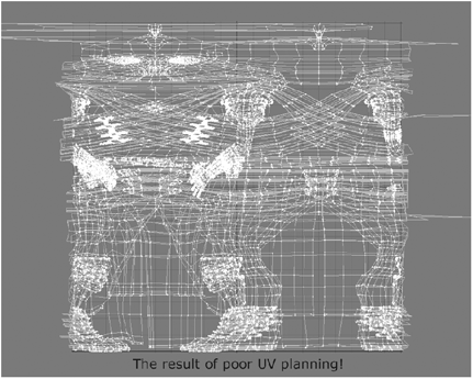
Figure 16-3
In most cases, a number of UV maps are required for any object that is more complex than a box. That is because even though UV mapping does flatten things out into a nice template that you can do whatever you want with, you still have to start with logical shapes.
For example, if you are unwrapping a human character, you cannot simply unwrap the entire model. You have to plan where to create the different UV maps, depending on the shapes found in the model. In this instance, it would be most efficient to unwrap the head, torso, arms, legs, hands, and feet separately, using unwrap projections most suited to the rough shape of the part.
Sure, this is quite a lot of work, but it is more efficient in the long run because editing an unwrapped map of an entire character would give endless problems. Planning your unwraps logically is therefore the best option. If a part of a model is more or less cylindrically shaped, then unwrap it cylindrically, whereas if another part is flat and more suited to planar unwrapping, then do that section with a planar unwrap. Simple.

Figure 16-4
All you need to do is take a good look at your model and divide it up into logical sections to unwrap, based on their shapes.
Another thing to consider is whether UV mapping is really necessary. In many texturing cases, the standard projection techniques discussed earlier will suffice, so why use UV mapping?
One of the interesting things about UV mapping is that technically it isn’t as accurate as the standard projection methods. Whereas the standard methods simply project the image straight onto the model without any regard to the actual polygon structure, and more importantly, the actual positions of vertices within the model, UV mapping uses the vertices in the model to place the map. Basically, the vertices are used like pins to attach the map to the model. Because of this, the areas between these points are interpolated, which, in basic terms, is an estimation. So the map is only technically accurate at the points, while the rest of the map is positioned as an estimation of where they should be, in relation to the positions of the points. A well-edited map will place the image nicely onto the model, but it will still not be as technically accurate as a normal planar projection, or any other kind of standard projection.
However, since standard projections are almost impossible to use when texturing very unevenly shaped objects, such as most organic objects, UV mapping is the best option.
It is important to only begin unwrapping when your model is complete. Making changes to a model after you have unwrapped it can often result in a lot more editing having to be done, and sometimes also requires changes to any texture maps you may have already made. It is extremely annoying to have to go back and re-edit parts of your map and parts of your actual textures, so be sure that you are 100% happy with your model before unwrapping and texturing.
Tips for Better UV Maps
To Freeze, Or Not to Freeze?
Bearing in mind what we have discussed regarding the manner in which the points within a UV map pin the texture to the model, it is only logical that the more points a model has, the more accurate the map is. This leads to a dilemma. Sure, you can increase the density of the mesh very easily, either by freezing it or by subdividing it further before unwrapping it, but do you really want to do that? We all know that it is good practice to keep the polygon count of a model as low as possible, even when working with high-resolution models, since, among other advantages, it keeps render times down and is easier to animate. However, if the model has a higher poly count, the UV map will be technically more accurate.
The thing to consider here is that a UV map of a dense mesh is a real pain to edit. Since it is almost impossible to use a UV map that has had no editing whatsoever (for the simple reason that it is highly unlikely that your initial unwrapping effort will be perfect), you have to remember that editing a UV map with a lot of polys is going to be a lot of work and, frankly, a bit more of a pain than is really necessary. Most UV maps need pretty extensive editing, and moving large chunks containing lots of polys around in your UV map is going to be really cumbersome and irritating, especially when you have to do it point by point, which is most often the case.
So you need to consider if it is really worth the effort. In my experience, I have never increased the poly count of a model simply for the sake of UV mapping, and I have never really felt that the resulting UV map was not accurate enough once I had edited it. So it is really up to you to decide on this one.
Multiple UV Maps in a Single Surface
Another problem encountered by many artists is the problem of using multiple UV maps on one surface. Using more than one UV map on a surface often results in oddities when rendering, and often also results in some of the maps not appearing to work at all. Although there are ways to fix this problem, I find that the easiest solution is simply to assign each UV map to a separate surface, if that is possible. While this method does indeed have drawbacks, such as the slight confusion of having so many surfaces applied to a model, it is sometimes nicer not to have to bother with covering up the problems of using multiple maps.
Another advantage of using separate surfaces is that, practically, it is easier to divide a model up into sections for mapping by initially assigning separate surfaces to each section that is to be unwrapped. This makes it easier to keep track of which part is which, especially if you assign a different color to each surface. Simple, yet effective.
Initial Placement of Seams
Choosing the correct center point for your unwrap is also important. If you have to unwrap a head, for example, the best way of unwrapping it would be to have the center of the UV map in the center of the model as well, so that the model is unwrapped from the center of the back to the front. Unwrapping the model in this fashion will ensure that the main seam for the map will run along the back of the head. A trick for doing this is to place your cursor at 0 (in the center, basically), rotate the model 90°, then unwrap it and rotate it back into position. This guarantees, in most cases, a seam that runs along the back of the model.
Figure 16-5 shows a head that has been unwrapped while facing forward. Notice the way that the seam is placed down the side of the face, just behind the left ear.

Figure 16-5
Now take a look at Figure 16-6. Here, I rotated the head −90° and unwrapped it. This resulted in the seam being placed down the back of the head, which is preferable since it is easier to conceal this seam when painting textures. This also makes the neck area easier to texture, since it is no longer separated from the lower jaw area, as in the previous example.
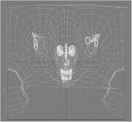
Figure 16-6
Using Parts
Another little something that makes the whole process a bit easier is to break your model up into parts. This makes for easier selections when unwrapping. I mentioned earlier that it is easy to keep track of your different sections by applying different surfaces to them, but another way is to select the polys that you wish to unwrap and assign a part name to them for easy selection at a later stage.
To group polygons into a part, you simply select them, go to the Display tab, click on the Grouping button, and select Change Part Name. By giving the selection a name, you can then easily select it again from your Polygon Statistics window (which you open by pressing “w”) by clicking on the Part button and selecting the part you want.

Figure 16-7
UVs and Subdivision Surfaces
Something that a lot of people complained about — and has been fixed — is the distortion that happened when unwrapping sub-d models. Now it really doesn’t matter if you unwrap your models with subdivision on or off since NewTek has added a feature called Subpatch Interpolation. UV maps used to get interpolated linearly even if the mesh was subpatched, which caused distortion of the textures. Now you have a total of five different UV interpolation options that will help get rid of the distortion problem once and for all.
Take a look at Figures 16-8 and 16-9. The first head was unwrapped with Linear interpolation, while the second is using Subpatch UV interpolation. Notice that the distortion is completely gone with Subpatch UV interpolation.

Figure 16-8: Linear interpolation

Figure 16-9: Subpatch UV interpolation
See “Fixing the Annoying Subdivision Distortion Problem — Interpolation Options” in Chapter 17 for more information on this wonderful new feature.
Don’t Panic!
Yes, UV mapping can seem very daunting at first, but do not worry — once you are comfortable with the whole process, you will realize that it is actually really not so big a deal. All in all, UV mapping is something that, once you have done it quite a lot, becomes extremely simple. You should find that you begin to develop your own habits and ways of doing things that make the process much simpler for yourself. Later on we explore all the tools that are used in the process, and many of them can have a number of interesting uses other than what they are specifically for.
Now that we are comfortable with the concepts of UV mapping, let’s move on to the actual types of UV mapping and start doing some unwrapping!
Planar UV Maps
Using Planar Maps
Planar UV mapping, much like its standard projection counterpart, is probably the simplest method of unwrapping. This is because it is generally quite predictable, in the sense that you know more or less what the resulting map will look like and what sort of editing it will require.
As a general rule, anything can be planar unwrapped. Although some maps might need a lot more editing than others, depending on their shape, planar unwrapping can often be the most efficient way of unwrapping objects. If you have the patience to edit it, you could even unwrap objects like heads or torsos or even limbs in a planar fashion, even though these sorts of objects are generally not flat in shape, which is what a planar solution is usually used for. This is the beauty of UV maps, that they can be edited, unlike standard projections that have problems of stretching along uneven topography, as in the case of the standard planar projections that we explored earlier.
Since we already have an understanding of how planar mapping essentially works (provided you have read the previous section of this chapter), learning how to make planar UV maps is pretty simple.
Basically what planar unwrapping does is it looks at the model along the axis that you specify and simply gives you a nice big flattened version of it along that axis. Of course this means lots of overlapping polygons in most cases (well, in any case that isn’t simply a one-sided box or something equally simple), but as mentioned before these can be fixed through editing.
As I mentioned at the start, practically anything can be unwrapped in a planar fashion, but of course this method is more suited to objects that are more or less flattish and lie predominantly along a single axis. So objects like swords, hands, books, walls, and the like are prime candidates for planar unwrapping.
Remember that because you can assemble a number of different UV unwraps into a single UV map, things like buildings work well using planar unwraps because you can unwrap each wall individually along its axis and assemble all the walls into a single UV map. This eliminates the need for loads of standard projections or boring repeating textures since you can then create the textures for each wall in one big image that is far more practical and convenient. (The Atlas unwrapping type that we look at a little later on is also useful for simple architectural unwrapping like this.)

Figure 16-10
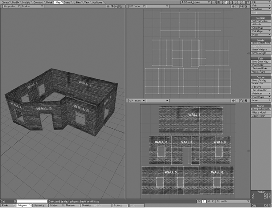
Figure 16-11
The example shown in Figure 16-11 was laid out in a matter of minutes by simply unwrapping each wall individually along its own axis and adding it to the UV map. Having each wall separate on a template then gives you the ability to easily paint individual textures for each wall without the hassle of using loads of different layers projected from different directions within the Texture Editor. This is a classic example of why UV mapping can be a convenient solution for texturing, even for relatively simple objects like buildings.
Planar UV Map Tutorial: Unwrapping a Sword
Let’s explore the process of creating a simple planar unwrap of a model, the object in this case being a sword.
1. Open Modeler and load the 4.2.2-sword.lwo object from the companion CD. A relatively simple sword model should now be showing in your viewports. As you can see, the model faces along the z-axis in Modeler and is fairly flat. This makes it an ideal candidate for planar UV projections.

Figure 16-12
2. Make sure that one of your models is showing the UV map template. To do this, simply click on the viewport view type at the top-left corner of any viewport, and select UV Texture. This is important because once we make our UV map, we can manipulate and edit the map itself within this particular viewport.

Figure 16-13
3. Select the polygons of the entire model. Go to the Map tab and under the Texture heading, select New UV Map. A new window pops up with a bunch of options for you to choose from, including what type of UV projection you would like, a field to enter in a name for the UV map, and some options for manually setting up the position of the map itself. By default this window is set to create a planar map, so all we need to do is enter in an appropriate name (just use “sword”) and make sure that the projection axis is set to the z-axis. Leave the other settings as they are, and click OK.
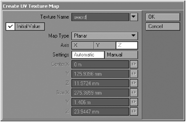
Figure 16-14
You might get a fright now when you see the projection appear in the viewport as it will appear squashed. Don’t worry — this is perfectly normal, and is easy to fix.
NOTE: When editing UV maps, it is very important to make sure that your mouse is within the UV Texture viewport only. Doing this will ensure that your changes will only be applied to the UV map, and not to the model itself. Anything that you do to the points and polygons within the UV Texture viewport will apply to the UV map only.
4. Now, while the polygons are still selected, select the Stretch tool (press “h”) and, ensuring that your mouse cursor is hovering within the UV Texture viewport, stretch the sword UV map until its dimensions more or less match those of the model itself. This is an adjustment that is approximately 20% horizontal and 120% vertical scale. Now select the Size tool (press Shift+h), and scale down the UV map so that it fits inside the square template within the UV Texture viewport.
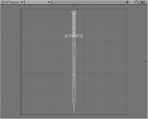
Figure 16-15
We are left with one slight problem. Since we have unwrapped the object straight along the z-axis that the model lies along, parts of the model are now overlapping in the UV map. Essentially what we have is both sides of the model being treated as a single projection within the UV map. So if we were to now paint a texture onto this UV map the way it is, both sides would look the same since the image would be projected straight through the front and back of the sword. So how can we fix this? Well, this is where the editable nature of UV maps really shines.
Before we do any editing, it’s always best to unweld all the points in your model. This is simply to prevent slight oddities that can occasionally occur within UV maps. As you can see, the sword is perfectly symmetrical, both on the x-axis and the z-axis.
5. Go into your Right viewport and select all the polygons on the right-hand side of the center line to select the “back” side of the sword.

Figure 16-16
If you now hover your cursor over the UV Texture viewport and drag your mouse to the left, you’ll see the entire back side of the sword move over the left side of the UV map, leaving the front side on the right, as shown in Figure 16-17.
This now means that because of the way in which the UV map is laid out, we can paint a different texture onto the front and the back of the sword because they are separate in the UV map, instead of overlapping one another. Don’t forget to hit “m” again to remerge all the points in the model that we unwelded!
This sword is now ready for some texturing, so go ahead and paint a nice texture for it. If you are not sure how to go about creating metal textures, then take a look at the tutorials in Part 7 for some tips!
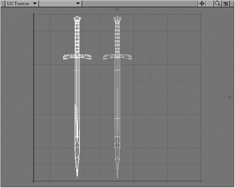
Figure 16-17
Cylindrical and Spherical UV Maps
Using Cylindrical and Spherical UV Maps
Cylindrical UV mapping is pretty much identical to its standard mapping counterpart of the same name. Just like we saw with standard cylindrical projections, the cylindrical UV mapping type splits the model along a seam that runs along a defined axis and spreads the rest of the model out from that point in a cylindrical fashion.
I use this type of mapping almost as often as planar mapping, since it is actually very versatile and highly suited to many organic shapes, especially in characters’ heads, arms, hands, and even torsos.
Spherical UV mapping, in practice, works in very much the same fashion as cylindrical mapping, which is why I am covering these two UV types in the same section. I have to admit, though, that I have actually never used a spherical UV projection, simply because cylindrical UV mapping always does the trick. Let’s face it — how often do you actually have to UV map a round object? A piece of fruit? A planet? A ball? All these can be done with standard spherical projections, and generally wouldn’t actually require UV mapping.
Let’s take a look at the same model unwrapped using the default settings of cylindrical mapping (on the left) and spherical mapping (on the right). See Figure 16-18.

Figure 16-18
As you can see, they are almost identical. The main area of difference is toward the poles, where the spherical map has a more pronounced distortion.
Placing the Initial Seam
Probably the most common use of the cylindrical projection is in unwrapping human heads. Most people model heads facing forward on the z-axis, and find that upon unwrapping the head, the seam (created by the manner in which cylindrical unwrapping works by splitting the model along the axis) is placed down the side of the face, usually just in front of one of the ears.
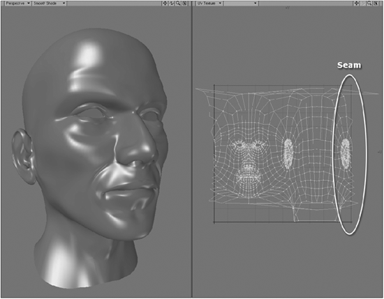
Figure 16-19
While we can obviously easily reposition this seam by moving the polygons in the UV map viewport, it can save a bit of hassle to place the seam in a more appropriate place initially.
The easiest way to do this is to rotate the object before unwrapping it.
Simply select your model, hit “y” to activate the Rotate tool, and then hit “n” to open its numeric control panel. It is better to do this operation with the numeric panel instead of rotating manually in the viewports because you have more precision this way and won’t risk changing the position of the model, which can happen when you rotate things by hand.
If your head is facing forward on the z-axis, enter a value of −90.0° along the y-axis.
Hit the Apply button, then unwrap the model cylindrically on the y-axis. Then go back to your Rotate numeric panel, and rotate the model back 90.0° on the y-axis and apply the transformation.

Figure 16-20
The seam is then placed along the back of the head, a far more convenient place for it to be, since it will likely be covered with hair.
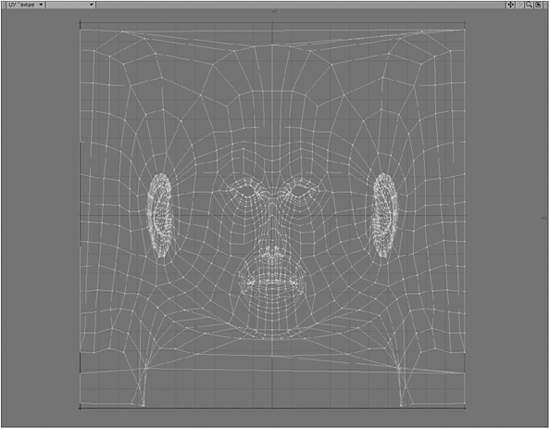
Figure 16-21
Cylindrical Map Tutorial: Unwrapping a Human Head
I thought it would be nice to do a fairly advanced UV mapping tutorial for this chapter, and since cylindrical mapping is so useful for human heads, let’s unwrap one of those.
1. Open the 4.2.3-head.lwo model from the companion CD in Modeler. This is a slightly Oriental male head, and I should mention that the ears were modeled by the fantastic South African LightWave artist Werner Ziemerink.

Figure 16-22
2. Rotate the head using the method described previously, using the numeric panel to rotate it −90.0° along the y-axis. Go to the Map tab and click on New UV Map. When the Create UV Texture Map panel pops up, give it a logical name like “Head” and select to unwrap cylindrically along the y-axis.
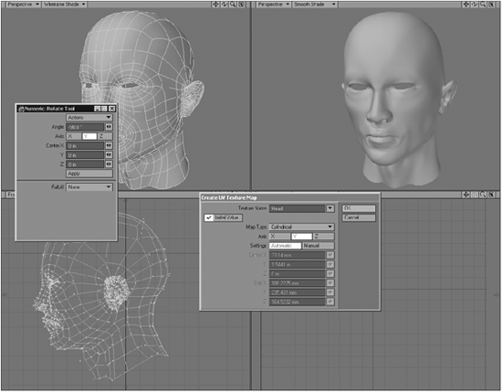
Figure 16-23
Rotate the head back 90.0° on the y-axis before continuing.
3. Now it’s time to edit. Go to your Display options (hit “d”) and change the Layout to Double Vertical.
4. Set up your two viewports so that one of them is a Perspective viewport that is set to Texture shading (top left of the viewport) and have the other viewport set to UV Texture.
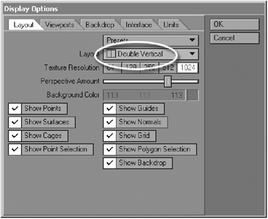
Figure 16-24

Figure 16-25
5. Open the Image Editor (Ctrl+F4) and load the _uv_checker.jpg image into Modeler. This loads a fairly large square image with a red and white checkerboard pattern.

Figure 16-26
6. Open the Surface Editor, go to the Skin surface, and open up the Color Texture Editor by clicking on the “T” button next to Color. Using the default layer that is created, change the Projection to UV, select the UV map you created for the head from the UV Map list, and select the _uv_checker.jpg image as the image. You’ll now see the image applied to the model in your Perspective viewport.
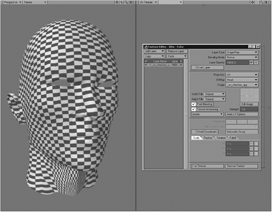
Figure 16-27
Looking now at the texture applied to the head in the viewport, we can immediately see where we need to adjust the vertices in the UV map to eliminate the stretching. (See Chapter 17 for more information about stretching and squashing in UV maps.)
7. Let’s start with the neck area first. As you can see, the checkerboard image is becoming squashed here, which means that the polygons for this area in the UV map are too large — hence they are allowing too much of the checkerboard image into that area.
So we need to move the points for this area inward to fix this problem. Go to your UV viewport, select the points immediately surrounding the middle points in the neck area, and move them inward so that they look like those in Figure 16-28.
Notice how this affects the texture applied to the model. The aim of editing this UV map lies essentially in getting the checkerboard as distortion-free as possible through adjusting the vertices. What it really comes down to is that you need to get the shape and size of the polygons in the UV map to proportionally match those in the model itself.
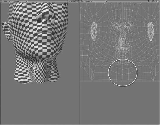
Figure 16-28
8. Let’s look now at the underside of the chin. Rotate your Perspective viewport, and you’ll see that the image has become very stretched under the chin.

Figure 16-29
When we look at this area in the UV map, it becomes obvious why this stretching is occurring. The polygons that form this part of the model have become totally squashed in the UV map, as shown in Figure 16-30.
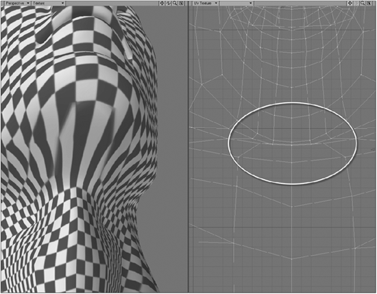
Figure 16-30
9. So what we need to do is pull these polygons downward to fix this area. Figure 16-31 shows how I have edited the area so that the image has become less stretched. It’s not always possible to totally eliminate stretching and squashing, but we should always try to eliminate it as much as we possibly can. I have drawn over the polygons in the image to make the editing a bit more obvious. Notice that I have also made some adjustments slightly lower down to reduce some of the previous distortion in the neck area.
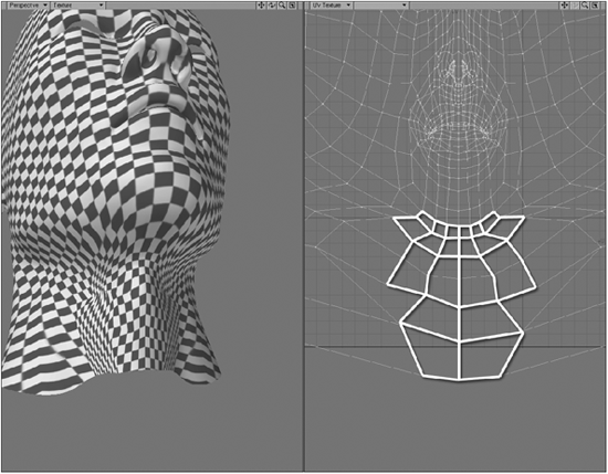
Figure 16-31
10. A little more tweaking, and the entire front of the neck area begins to look correct. This involved not only shifting and arranging the vertices inward, but also selecting the polygons in the UV map themselves and actually using the Stretch tool to stretch them inward.

Figure 16-32
This editing has now caused areas on the side of the neck to become squashed. This is simply because I have been shifting things inward, and the polygons on the neck that now look squashed in the Texture viewport look like that because they have become too large in the UV map, thereby causing too much of the image to become squashed into that area.

Figure 16-33
11. All we need to do to fix this is obviously continue to move the vertices in this area inward so that the polygon in the UV map is no longer so stretched. You’ll find that as you edit certain areas, you’ll also need to readjust areas directly surrounding them to allow everything to shift smoothly into place. Remember, don’t panic if you cannot get the checkerboard 100% perfect on the model; you just need to remove the major stretching and squashing.

Figure 16-34
12. Zoom in on the parts of the texture where it has little wiggly distortions in it, as shown in Figure 16-35.

Figure 16-35
These distortions are caused by the subdivision of the model and cannot actually be perfectly fixed, since they are an artifact of LightWave’s subdivision algorithm. So don’t worry about them too much.
13. If we zoom out of the model now and take a look at the entire thing, it becomes obvious that the whole map is a little too stretched along the y-axis. In the UV map, this is the v-axis, and we need to scale the map down along this axis to fix this.
However, because of the nature of discontinuous UV maps in LightWave, we need to unweld the points in the model before scaling them; otherwise, parts of the model are going to remain stuck in place.
14. Press Ctrl+u to unweld all your points. The model will look a bit odd in your viewport if you were displaying your model in Subpatch mode (Tab), so generally I just press Tab again to go to normal Polygon display mode.
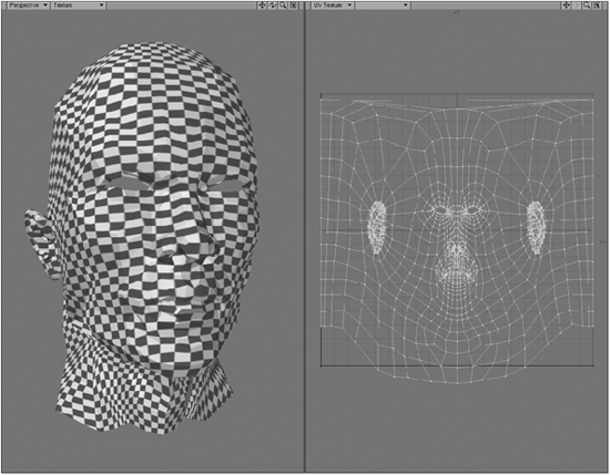
Figure 16-36
15. Now go to your UV viewport, select all the polygons, and press the “h” key to activate the Stretch tool. Holding down the Ctrl key (to constrain the stretching to a single axis), squash the polygons downward to squash them along the v-axis. Squash the polygons until the squares in the texture begin to look more square instead of rectangular.
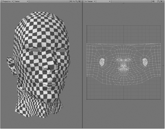
Figure 16-37
16. Press the “m” key to merge your points again before continuing.
Of course, this squashing altered some of the editing we did previously, but you don’t really need to worry all that much about it, because the squashing now on the neck is relatively minimal and is not likely to cause problems when you paint a texture for it later on.
17. Let’s now focus on the top of the head. Rotate your Perspective viewport so that the top of the head is visible. You’ll see some nasty pinching at the pole where the cylindrical map comes to a point.
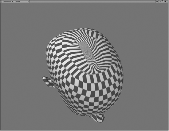
Figure 16-38
To be honest, there is no real point in spending much time actually editing this to fix it because you’ll more than likely cover this area with hair, using Saslite or Sasquatch, or even modeled hair. If you want the character to be bald, it would be better to create an additional planar projection along the y-axis (just a standard projection; no UV map necessary) of the top of the head, and blend the two textures together using an alpha channel or Falloff settings in the Texture Editor.
So this pretty much concludes the process of editing the UV map for a head. Some people like to create additional projections for the ears as well, but that isn’t always entirely necessary, as ears generally don’t tend to have much texture detail on them. It’s up to you, and since you now have this model, you’re free to do with it as you please.
Atlas UV Maps
Using Atlas Maps
Aaaah, the ever-tempting Atlas unwrap option. This often looks extremely alluring to use since it gives the impression of being an ideal option for anything. Let me quickly banish that idea. Although the idea of an atlas unwrap seems like a great one, more often than not the result is a disjointed mess, especially when unwrapping organic models. In my experience, this option is not really suitable for characters (or any organic objects, for that matter) unless you want to spend a really, really, really long time editing the map.
The following image demonstrates the fragmented chaos that results from unwrapping a simple head object.
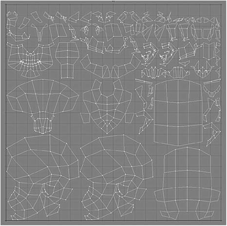
Figure 16-39
Figure 16-40 shows the same map after about an hour of editing, and it still needs a lot more editing before it can be of any use.

Figure 16-40
The fragmentation that occurs from unwrapping using the Atlas unwrap option makes it disastrous for anything other than structures such as buildings, cars, or anything else that has mostly retained simple shapes (primitive shapes).
Atlas unwrap does have one main advantage: It can be used to unwrap an entire object, regardless of the orientation of any part of that object. This is because atlas does not use an axis to unwrap; it simply flattens out the entire object along an arbitrary axis. Pretty cool!
So basically, you do not have to worry about choosing the right axis along which to unwrap, depending on what sort of alignment the different parts of the model have. Instead, it is simply a matter of clicking to unwrap, and then dealing with the resulting map as it turns out.
In the case of atlas mapping, editing is essentially the key to success, as the result of the initial unwrap is so very unusual. Atlas maps are always very fragmented, no matter what settings you use. Of course, as we know, editing is essential in all unwrapping methods, but in this case it takes on more importance since the initial unwrap is, in almost every case, totally unusable without extensive editing. This only really excludes extremely simple buildings, which, although they can definitely be improved by editing, can use the initial map obtained in many circumstances.
When editing atlas unwraps, one tends to use tools such as Flip UV Point Map a lot, since many polys often become flipped when using this method. We explore all the UV editing tools in great depth in Chapter 17.
Making an Atlas UV Map
To make an atlas UV map, select the model that you wish to unwrap, click on New UV Map on the Map tab in Modeler, and select Atlas.
You’ll notice that the Atlas UV mapping type has a different setup of options compared to the Planar, Cylindrical, and Spherical types.
The Relative Gap Size option defines the distance between the fragmented sections of the map. Larger values will cause the sections to be farther apart from one another in the map, but remember that since the entire map needs to fit into the square UV template that is a finite size, increasing this value also means that each part will be smaller in the UV map. If you want to paint really fine details into your textures, you are going to have to create much larger images for your textures since each part is so small within that map.
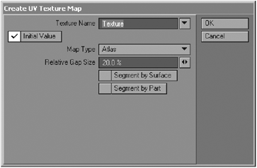
Figure 16-41
The following image shows an unwrapped cube with a Relative Gap Size value of 20% (on the left) and one with a value of 80% (on the right). I have drawn over the map with bolder lines to make the details clearer.

Figure 16-42
The Segment by Surface and Segment by Part options allow you to specify whether the discontinuities in the UV map will be positioned according to different surfaces or parts assigned to the model that you are unwrapping. For more information on discontinuous UVs, refer to Chapter 17.
So if you have, for example, three different surfaces assigned to the model, you can choose to have the fragmentation defined by these different surfaces. The same would apply to any parts that you have created in your model (parts are groups of polygons that you can define under the View tab in Modeler).
Atlas UV Map Tutorial: Unwrapping a Small Building
This tutorial demonstrates the use of Atlas UV mapping to unwrap a small building. We will unwrap the outer walls first, and then do the inner walls.
1. Open the 4.2.4-small_house.lwo object from the companion CD in Modeler.

Figure 16-43
2. The roof and the walls are on two separate layers. Let’s go to the wall layer and concentrate on that one first. Select all the outer walls of the house. I have already assigned a separate surface to them for ease of selecting, so all you have to do is open the Polygon Statistics panel (hit “w”) when in Polygon mode (Ctrl+h), go down to where it says Surf, and select the Walls Outer surface. Click on the little + symbol to select the polygons to which this surface is applied.
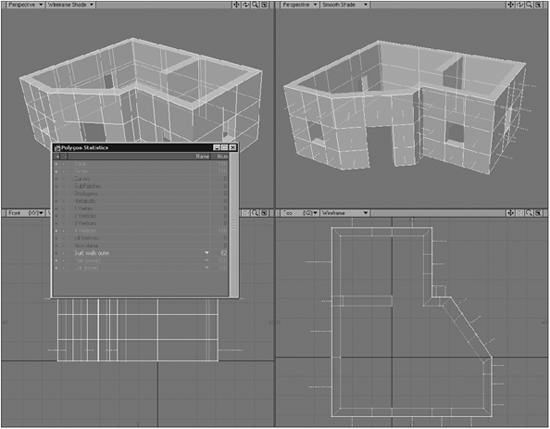
Figure 16-44
3. Go to the Map tab and click on New UV Map. Select Atlas as the Map Type and give it the name “outer walls.” Leave the other values as they are and click OK.
4. Change one of your viewports to UV Texture, and the map should automatically be displayed in the viewport. As you can see, all the walls are nicely flat in the UV template.
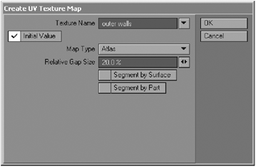
Figure 16-45
5. Open the Image Editor and load the _uv_checker.jpg image from the companion CD.
6. Open the Surface Editor, go to the Walls Outer surface, and open the Color Texture Editor. Change the default layer Projection setting to UV, select the “outer walls” UV map from the UV Map list, and load the checker-board image.
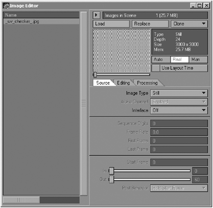
Figure 16-46
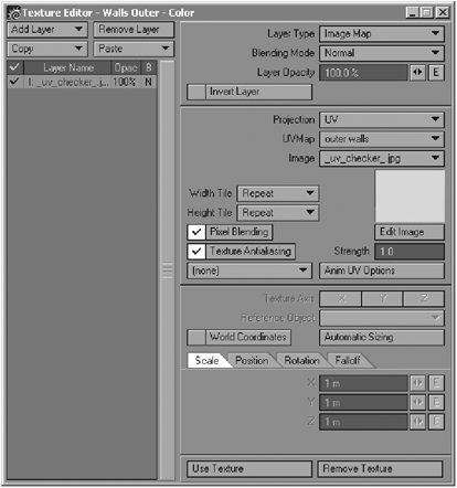
Figure 16-47
Make sure that your Perspective viewport is set to display textures, and you’ll see the checkerboard image applied to the model. The outer walls, as you can see in Figure 16-48, are almost perfect.
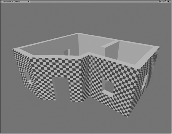
Figure 16-48
If we look at the area immediately to the right of the doorway, we can see that the checkerboard image is slightly squashed in this area.
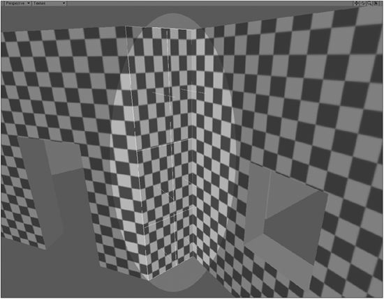
Figure 16-49
7. These polygons are slightly too wide in the UV map, so we need to use the Stretch tool to fix this. You will have to unweld the vertices before doing this though, as this area is discontinuous, so press Ctrl+u to unweld the points before using the Stretch tool.
8. Now select the polygons that we need to squash, go to the UV viewport, select the Stretch tool (“h”), and squash the polygons inward along the u-axis (horizontally) until the patterns become square instead of rectangular, as shown in Figure 16-50.

Figure 16-50
Leave all the points in the UV map unwelded for now.
At the moment, the walls in the map are not positioned alongside their correct counterparts. In other words, the walls in the UV map are not necessarily flanked by the walls that are actually next to them in the model. So ideally we need to arrange them correctly in the UV map to make the texture painting simpler, since there will be fewer seams to deal with.
9. Let’s start with the door area and the piece of wall to its left. Select the polygons in this area. You’ll notice that in the UV map, these two parts of the wall do happen to lie alongside one another. In Figure 16-51 I have made the selection in the UV map bolder so that you can see more clearly what you need to be doing.

Figure 16-51
10. Move these out of the actual UV area so that we can start arranging things correctly. Move them up and position them above the actual UV map. When you select the polygons to move them, do so in Point mode (Ctrl+g) instead of Polygon mode. Moving the polygons around in Polygon mode sometimes leaves points behind.

Figure 16-52
11. Now let’s move clockwise around the house and move the walls in the UV map into place. Rotate your Perspective viewport around so that you can see the walls to the left of the section we just moved. Select them in your viewport so that you can see where they are in the UV map. We want to have these positioned directly to the left in the UV map as well, so select the points of this section in your UV viewport, and move them up and to the left of the area we moved previously.

Figure 16-53
Rotate your Perspective viewport now so that you can see the back of the house.
You’ll notice something a bit odd. In your Perspective viewport, select these polygons from left to right and watch how they are selected in the UV viewport at the same time. Notice something a bit odd? Yes, they are backward!
12. No need to panic — this is a common occurrence in atlas UV maps. All we need to do is use the Flip UV command to fix it. Select all the points of that section of wall and click on the Flip UVs button. Select Flip U and click OK.

Figure 16-54
This flips the points horizontally, so that they now flow correctly.
13. Select the points for this section and move them into place on our row of walls. Move them up to join with the new row of walls we are building at the top of the UV map.
Figure 16-55
14. Swivel your Perspective viewport around to the side of the house now, and select the walls there. Move them into position on the new row at the top as well, and then repeat this process for the next section.
15. Last, we have the little piece that we squashed earlier. If you select these polygons from left to right in the Perspective viewport while looking at the UV viewport, you’ll notice that these polygons are also flipped incorrectly. Once again, simply select the points of this section, hit the Flip UVs button, and select Flip U. Then, move this section into place on the row of walls.
16. Now select all the points in this long row of walls, scale them down, and position them back into the actual square template of the UV map.
17. Because they are so small in the UV map now, you will need to create a very large texture map to get detail into these small areas. Since we still have so much room going to waste in the UV map, select the points of the polygons forming the front and left facades of the house and move them below the other row. You’ll ideally need to rearrange the sections forming the front part a little, so that the part that is to the right of the door part is now to its right in the UV map (previously it was on the other end of the row from that section).
18. Scale these sections up as much as you can in your UV map now, and it should look like Figure 16-56.
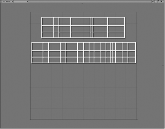
Figure 16-56
19. Okay, so let’s move onto the inner walls of the house. Select them by surface from the Polygon Statistics panel (“w”), and click on New UV Map. Select Atlas and call the map “inner walls.” Leave the other settings as they are.

Figure 16-57
20. You’ll get a nice big fragmented map looking like Figure 16-58.

Figure 16-58
You are probably freaking out right now, but relax because I have some good news for you. Remember when we unwelded the points earlier? Well, because the entire model was unwelded, LightWave has assumed that all the pieces are separate, and so it has not kept them intact when it unwrapped the model.
21. So press Ctrl+z to kill the UV map.
22. Merge all the points in the model again by pressing “m.” Now create the UV map again, using the same settings I described in step 19. Ahh, that’s much better.
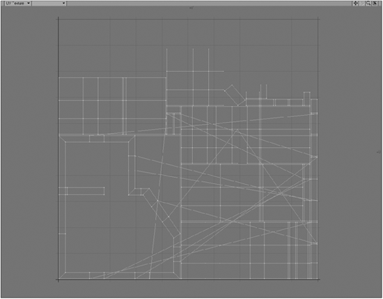
Figure 16-59
Don’t worry about all the criss-crossing lines everywhere; they are only there because pieces of wall that should be alongside each other currently are not. Once we have edited the map, those lines will no longer be there.
23. Go to the Surface Editor, select the Walls Inner surface, and load the _uv_checker.jpg image into the Color Texture Editor, using the “inner walls” UV map.
24. Now we need to unweld again because we don’t want to be bothered with discontinuities while editing. So press Ctrl+u to unweld all the points.

Figure 16-60
25. Now simply do the same as we did with the outer walls by selecting each section, moving it up to the top, and arranging a nice long row of wall sections. Watch out for flipped polygons, as a few of the sections in this map are flipped the wrong way on the u-axis in the UV map.
Figure 16-61 shows the long row I made, starting from the left side of the back inner wall on the left end of the row.

Figure 16-61
26. Once you have them all in a row, split the row into two again, and arrange them so that they will fit into the UV map space.
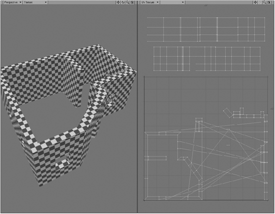
Figure 16-62
27. Okay, now we are left with a bunch of polygons that form all the horizontal parts of the model. First, we can get rid of the top row that runs along the top of the walls because the building has a roof and we will therefore never see those polygons. Select them in your Perspective viewport, and then click on Clear Map. This will remove them from your UV map. They will leave some points behind in the UV map — select those points and click on Clear Map again to delete them from the map.

Figure 16-63
28. Now we are left with the window ledges, the inner doorframe, and a mess of weird, distorted polygons. Let’s deal with the weird ones first. Select them in your UV viewport.
You’ll notice that they are actually polygons on the outside walls, so we don’t need them here either. Click on Clear Map again while they are selected. Select any points that they leave behind and clear those as well.
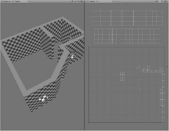
Figure 16-64
29. All that we have left now are the doorframe polygons and window ledges. You are really free to arrange these to your own personal preference. Personally, I really couldn’t be all that bothered about them, so I just arranged them all along the bottom of the UV map. If you really want to, you can arrange them inside the window holes in the appropriate sections in the parts you’ve been editing. Now arrange everything snugly into the UV space.

Figure 16-65
And that’s atlas UV mapping. A lot of moving things around and rear-ranging, but useful for situations like this.
30. Merge your points by pressing “m.” And that’s it!