
Chapter 26
Architectural Surfaces
Architectural Surfaces Tutorial: Stairway
Architectural images are extremely popular these days, with entire studios dedicated only to architectural visualization work. You can show clients images of their building’s exterior or interior long before a single nail is hammered or walls get painted. FPrime helped bring LightWave to this market mostly due to its sheer speed. You can render images using radiosity at a fraction of the time than you can with LightWave alone. In this tutorial I wanted to do something a bit different from the average room. We are going to texture a daylight-lit basement stairway. Besides good textures, good lighting is essential for architectural renders. Remember that good textures make your models but good lighting makes your scene! Since I would like to use FPrime to render this image, we will be texturing it with the “classic” Texture Editor by adding layers to the surface just like the guitar tutorial. If you don’t have FPrime, you can render with LightWave’s standard radiosity, but it will take longer.
The Model
This model is quite simple: a few walls, a ceiling, floor, a window, and of course the stairs. The model contains weight maps that we will use to control certain aspects of the textures. In general, it is a simple model and what makes it look nice is the texturing and lighting. To get a bit of a nostalgic feeling, I modeled a couple of toys to be added to the scene later.
Surfacing the Room Elements
In this tutorial we are going to use the “classic” Texture Editor using layers. I would also like to use FPrime for rendering this image and since at this point it does not take advantage of nodes, we have to stick with layers.
1. Set the content directory in LightWave to the Stairs folder inside the Tutorials directory of the companion CD (“o” on the keyboard, then “Paths”). After setting the content directory, load the scene called Stairs.lws.
Most of the surfaces in this room are quite simple. The procedurals used are subtle as well; it is a good idea to build your textures slowly, one by one, and fine-tune from there. The biggest problem with that approach is that it will be difficult to see exactly what the textures are doing separately. So if you think you are going to need four different procedurals or images to achieve the look that you are after, just add the layers one by one and see their effect. Another suggestion I can give you when using procedural textures is to change the texture color to a very bright, vibrant color like a bright red. This makes the procedural really stand out and the patterns will be clearly visible; then after you are happy with the texture, change the color to a more appropriate one.
2. Before you start, if you would like to see what you are doing interactively, activate VIPER, create a new camera in the scene, and leave it at its default settings. Make a test render so the buffers can be saved for VIPER.
During the surfacing session you can move this camera to the specific area that you are working on and have a clear view of the surface in the VIPER window. Every time you move the camera to a new location you need to make a new render in order to update VIPER’s buffers; if you have FPrime a new render is not needed, as the previewer will update automatically.
3. Let’s begin with the walls. There is not much going on here, so you just have to decide the type of paint finish that you would like to have for them. In this case I’m going for a semi-gloss finish. I changed the base color of the walls to a beige color: 217, 205, 164.
4. Click on the “T” button to open the Texture Editor of the Color channel and change the default layer to a Crumple procedural texture. Change the texture attributes as follows:

Figure 26-1: Color layer
Layer Opacity: 5%
Texture Color: 204, 10, 1
Frequencies: 2
Small Power: 0.536
Scale X: 5m, Y: 5m, Z: 5m
This layer is very subtle, but it breaks up the base color a little so it isn’t completely even.
5. For the Diffuse channel, lower the amount to 95%; semi-gloss paint reflects quite a bit of light so a nice bright color for the surface would be ideal. We can use procedural textures to break it up a little. Click on the “T” button of the Diffuse channel to open the Texture Editor. Add a Turbulence layer with the following values:
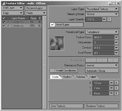
Figure 26-2: Turbulence layer
Layer Opacity: 15%
Texture Value: 80%
Frequencies: 3
Contrast: 0%
Small Power: 0.5
Scale X: 10mm, Y: 7mm, Z: 4mm
6. To randomize it a bit more, add another Turbulence layer with these values:
Layer Opacity: 5%
Texture Value: 9%
Frequencies: 3
Contrast: 78%
Small Power 0.92
Scale X: 5m, Y: 5m, Z: 5m
7. We need to make exactly the same Turbulence layer for the Specularity channel that we made for the Diffuse channel. Instead of making the layer from scratch again, go back to the Texture Editor of the Diffuse channel by clicking on its “T” button. Select the Turbulence layer on the bottom of the stack, then click on the Copy pull-down menu button above the layer stack and choose Selected Layer(s). Next click on the “T” button of the Specular channel to open its Texture Editor and click and hold on the Paste pull-down menu and select Replace All Layers.
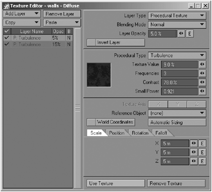
Figure 26-3: Second Turbulence layer
8. Keep the Glossiness channel with a low value, like 5%. Since the paint that we are trying to mimic is semi-gloss, add a tiny bit of reflection, such as 2%.
9. The last channel for the walls surface is Bump; again paste the same Diffuse Turbulence layer that we also used for the Specular channel.
10. Next, let’s make some imperfections on the wall’s surface. Sometimes when you paint walls you’ll notice that the wall is not 100% smooth. It might have dents or plaster bumps, or it may have been painted with low-quality tools, such as cheap rollers or brushes that can lose fibers or hairs that get mixed with the paint (I hope my mom reads this). To mimic all these imperfections you can use a Dented procedural texture. Add this Dented layer on top of the Turbulence layer and change the following values:

Figure 26-4: Dented layer
Layer Opacity: 100%
Texture Value: 42.5%
Scale: 1.45
Power: 5.0%
Frequency: 0.75
Octaves: 3.6
Noise Type: Perlin Noise
Scale X: 15mm, Y: 15mm, Z: 15mm
11. I didn’t spend too much time on the window surfaces since they won’t be visible in the final render and any textures added to it will have some impact on rendering time. I thought of just using some basic channel settings, like lowering the Diffuse and increasing Specularity and Glossiness. The only surface that is really important is the glass of the window since the rays produced by Ray Tracing need to go through the glass and into the room. Select the “Glass” surface and change these channel values:

Figure 26-5: Glass surface
Color: 200, 200, 200 (gray)
Diffuse: 100%
Specularity: 30%
Glossiness: 70%
Reflection: 10%
Transparency: 90%
Refraction Index: 1.2
Smoothing: On
Double Sided: On
12. Now let’s surface the hand rail. It consists of three surfaces: the painted wood, the gold-colored support, and the screws. I wanted to surface the wood surfaces in the scene other than the steps to make them look like they could use another coat of paint, so I use a very light gray base color, like RGB 240. Click on the “T” of the Color channel to open the Texture Editor and add a Cyclone layer. This is a rarely used texture, and I thought this would be a great example of showing this texture being used in something other than… err, cyclones. After the layer is created, dial in these values:
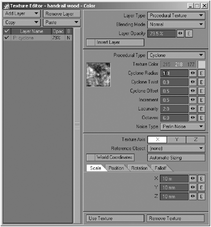
Figure 26-6: Cyclone texture
Layer Opacity: 79.5%
Texture Color: 215, 218, 177
Cyclone Radius: 1
Cyclone Twist: 0.9
Cyclone Offset: 0.5
Increment: 0.5
Lacunarity: 2
Octaves: 6
Noise Type: Perlin Noise
Texture Axis: X
Scale X: 10m, Y: 10mm, Z: 10mm
13. For the other surface channels, just dial in these values:
Diffuse: 90%
Specularity: 10%
Glossiness: 32%
Reflection: 3%
14. For the Bump channel we need to copy the Cyclone layer from the Color channel. Click on the Color channel’s “T” for the Texture Editor and copy the Cyclone layer. Now click on the Bump channel’s “T” button for the Texture Editor and paste the Cyclone texture layer. Add a Dented layer on top of that for extra detail as seen in Figure 26-7:

Figure 26-7
Layer Opacity: 100%
Texture Value: −42%
Scale: 2.5
Power: 5
Frequency: 0.75
Octaves: 3
Noise Type: Perlin Noise
Scale X: 20m, Y: 10mm, Z: 10mm
15. The metal details of the handrail are easy enough; just remember that for good metals you need low Diffuse and high Specular values. Make the base color of the gold accent 244, 208, 114. Then click on the Color channel’s “T” once again, and change the default layer to a Turbulence procedural with these settings:
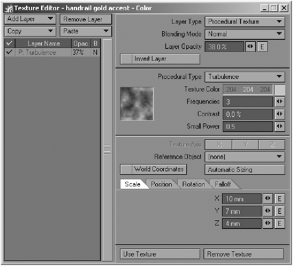
Figure 26-8: Gold-colored layer
Layer Opacity: 38%
Texture Color: 204, 204, 204
Frequencies: 3
Contrast: 0%
Small Power: 0.5
Scale X: 10mm, Y: 7mm, Z: 4mm
16. Use a gradient for the Diffuse channel. Create one extra key and put it on the bottom of the gradient. Make the Layer Opacity 80%, select Incidence Angle as Input Parameter, and set in these values for the keys:
17. This gradient will cause the surface’s Diffuse to increase incrementally toward the surface edges, creating the effect of a subtle rim highlight. Now change the following channel values:

Figure 26-9: Incidence Angle gradient
Diffuse: 35%
Specularity: 55%
Glossiness: 34%
Reflection: 50%
18. Now you have a pretty convincing metal. Before we move on to the screws, let’s add some bump detail to the metal. Add a Turbulence procedural texture with the following values:
Layer Opacity: 20%
Texture Value: 10%
Frequencies: 5
Contrast: 0
Small Power: 1
Scale X: 7mm, Y: 7mm, Z: 7mm
19. Add a Dented texture layer to add variation to the texture:
Layer Opacity: 100%
Texture Value: 42.5%
Scale: 1.45
Power: 5
Frequency: 0.75
Octaves: 3.59
Noise Type: Perlin Noise
Scale X: 7mm, Y: 7mm,
Z: 7mm
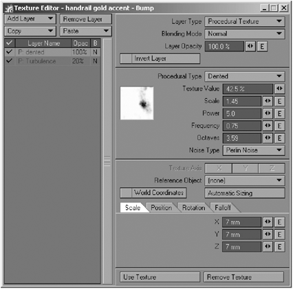
Figure 26-10: Dented texture
20. These layers combined will create the look of some wear and tear on the surface, but it isn’t strong enough to overpower the surface. Use this texture for the screws as well, but change it slightly so it isn’t an exact copy. Right-click on the handrail gold surface and copy it, then right-click on the screws surface and paste it. Get rid of the bump map for the screws; they are so tiny that it will not make a difference to the final image and the procedurals won’t have to be calculated. Change the basic surface properties to these:
Color: 223, 233, 233 (light gray)
Diffuse: 60%
Specularity: 100%
Glossiness: 24%
Reflection: 5%
21. Add a gradient in the Reflection channel and select Incidence Angle as the Input Parameter. Leave the default key as is and add an extra key with a Value of 11.5 and a Parameter of approximately 72.9. This will make the edges of the object more reflective.
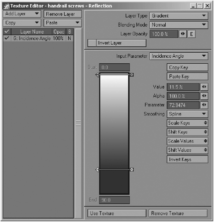
Figure 26-11: Reflection gradient
22. For the “steps sides” surface, make the base color burgundy to create a good contrast with the beige walls, something like 138, 38, 12. Click on the “T” button to add some texture layers to the surface. Make the first layer a red Crumple procedural texture. Change the Blending Mode to PShop Multiply; this will multiply the color information with the base color, resulting in a slightly darker color. Remember, subtlety is key. Having this in mind, use the following values:

Figure 26-12: Crumple color layer
Layer Opacity: 5%
Texture Color: 204, 10, 1
Frequencies: 2
Small Power: 0.536
Scale X: 5m, Y: 5m, Z: 5m
23. To add some tear and wear discoloration, add a Dented texture layer with the following settings, as seen in Figure 26-13:
Layer Opacity: 100%
Texture Color: 255, 255, 255
(white)
Scale: 2.5
Power: 5
Frequency: 0.75
Octaves: 3
Noise Type: Perlin Noise
Scale X: 20m, Y: 1m, Z: 1m
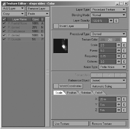
Figure 26-13
24. To make this texture more interesting and natural, add a Turbulence layer to the stack. Leave all the settings at their defaults with the exception of Contrast, which should be set to 49%. Also change the Blending Mode to Texture Displacement; this will disturb the texture that sits right above it. Add another Dented texture to the stack (Figure 26-14); this will be the texture that will be displaced by the Turbulence layer. Change the following:

Figure 26-14
Layer Opacity: 20%
Texture Color: 255, 198, 174
Scale: 1.71
Power: 5
Frequency: 0.75
Octaves: 3
Noise Type: Perlin Noise
Scale X: 50mm, Y: 50mm, Z: 200mm
25. Now we have some nice streaks caused by the Turbulence layer underneath. The only problem with this as it stands right now is that it covers the whole surface equally and is thus a dead give-away of the procedural pattern. To correct this, add a Fractal Noise layer to the stack, and change the Blending Mode to Alpha and the Contrast to 1.45. Now the Dented texture below will fade in some areas and therefore eliminate the too even pattern.

Figure 26-15: Alpha layer
26. For the Diffuse channel, lower the amount to 95%, click on its “T” button to open the Texture Editor, and add a couple of Turbulence layers to add variation to the diffuse values, as shown in Figures 26-16 and 26-17.
Layer Opacity: 15%
Texture Value: 80%
Frequencies: 3
Contrast: 0%
Small Power: 0.5
Scale X: 10mm, Y: 7mm, Z: 4mm

Figure 26-16
Layer Opacity: 3%
Texture Value: 80%
Frequencies: 3
Contrast: 78%
Small Power: 0.92
Scale X: 2m, Y: 2m, Z: 2m

Figure 26-17
27. Back in the Surface Editor change the Specularity channel value to 10% and Glossiness to 17.5%. Sometimes you can get away with just fine-tuning these values, but it depends on the surface and the look you are going for. In this case, leave Glossiness as is but add a simple Turbulence layer to the Specularity channel:
Layer Opacity: 15%
Texture Value: 80%
Frequencies: 3
Contrast: 0%
Small Power: 0.5
Scale X: 10mm, Y: 7mm, Z: 4mm
28. Almost done with this surface… it just needs some bumps and dents. Go to the Specular channel and click on its “T” button to open the Texture Editor and copy the Turbulence layer. Go back to the Bump Texture Editor by clicking on its “T” button and replace the default layer with the one that we just copied. On top of that create a Dented texture to add imperfections to the surface:
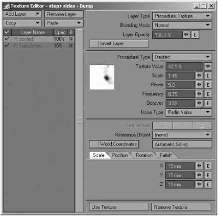
Figure 26-18: Dented bump layer
Texture Value: 42.5%
Scale: 1.45
Power: 5
Frequency: 0.75
Octaves: 3.6
Noise Type: Perlin Noise
Scale X: 15mm, Y: 15mm, Z: 15mm
29. We have two of the main surfaces left to do: the “wainscoting” and “steps tops” surfaces. Copy the “handrail wood” surface and paste it on the wainscoting surface. Since this surface doesn’t see as much traffic as a handrail would, let’s change the Specularity channel to 20%, the Glossiness channel to 15%, and Reflection to 5% to make it a little glossier looking than the handrail.
30. The surface called “steps tops” is probably the most challenging one of the bunch. Let’s start with the Color channel; copy the base color texture layer, Cyclone, from either the handrail wood or wainscoting surface, then click on the steps tops surface and click on the Color channel “T” button and replace the default layer with this one to make it the base texture as well. Now, create a Turbulence layer to be used as a displacement, just like we did before, with the following settings:
Layer Opacity: 100%
Texture Color: 204, 204, 204 (light gray)
Frequencies: 3
Contrast: 87.5%
Small Power: 0.505
Scale X: 2m, Y: 2m, Z: 2m

Figure 26-19: Displacement texture
31. Add a Dented procedural texture layer to the stack and change the following:
Layer Opacity: 15%
Texture Color: 138, 38, 12
Scale: 4
Power: 5
Frequency: 0.75
Octaves: 3
Noise Type: Perlin Noise
Scale X: 40m, Y: 20mm, Z: 20mm
32. Let’s add some color variation to the surface using a gradient. Add the gradient to the stack, then change the Blending Mode to PShop Multiply and the Layer Opacity to 35%. The model contains a weight map called “steps.” Use this map to drive the gradient by changing the gradient Input Parameter to Weight Map, and selecting the map from the pull-down menu. Figure 26-21 shows the “steps” weight map. You can also load the model into Modeler and take a look at the map there. We need three keys in this gradient with the following values from top to bottom (see Figure 26-22):

Figure 26-20: Dented layer
Key 1
Color: 000, 000, 000 (black)
Alpha: 36%
Parameter: −100%
Key 2
Color: 255, 245, 213
Alpha: 44%
Parameter: 21%
Key 3
Color: 146, 121, 71
Alpha: 34.5%
Parameter: 100%
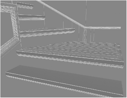
Figure 26-21: “Steps” weight map

Figure 26-22
33. To finish the Color channel, copy the Turbulence displacement layer and paste it below the gradient so it too gets displaced.
34. For the Diffuse channel, just lower the amount to 90%.
35. Let’s jump to the Bump channel — lots to do there. You know what’s next… click on the Bump channel’s “T” button and paste the same Cyclone texture that you used before. Add a Dented procedural to the stack (Figure 26-23), and change the following values:
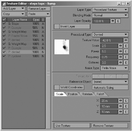
Figure 26-23
Texture Value: −42%
Scale: 2.5
Power: 5
Frequency: 0.75
Octaves: 3
Noise Type: Perlin Noise
Scale X: 20m, Y: 10mm, Z: 10mm
36. This surface should show heavier wear and tear than the rest of the surfaces of the room, so let’s add some bumps and dents to the edges of the steps. Add a Crumple texture, change the Opacity to 50%, and change these attributes (see Figure 26-24):
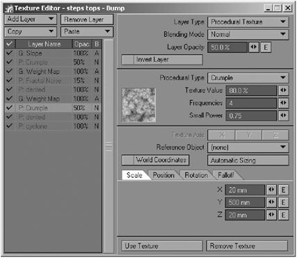
Figure 26-24
Texture Value: 80%
Frequencies: 4
Small Power: 0.75
Scale X: 20mm, Y: 500mm,
Z: 20mm
37. In order to isolate this texture to the edges of the steps, we can reuse the weight map that we already have available, so create a gradient with the Blending Mode set to Alpha and the Input Parameter set to Weight Map, and pick the “steps” map from the pull-down menu. You can load the object in Modeler and see what this weight map looks like to get a better idea of what areas you are isolating with it. We need the following keys in the gradient:
Key 1
Value: 0%
Alpha: 100%
Parameter: −100%
Key 2
Value: −10%
Alpha: 100%
Parameter: 0%
Key 3
Value: 0%
Alpha: 100%
Parameter: 54%
Key 4
Value: 100%
Alpha: 100%
Parameter: 100%

Figure 26-25: Weight alpha gradient
38. Copy the Dented layer already on the stack and paste it to add a copy, keeping everything the same with the exception of the Scale tab values set to X: 40m, Y: 20mm, and Z: 20mm. Let’s add another layer of bumps to the edges of the steps. Add a Fractal Noise texture to the stack, change the Opacity to 15%, and change these values:
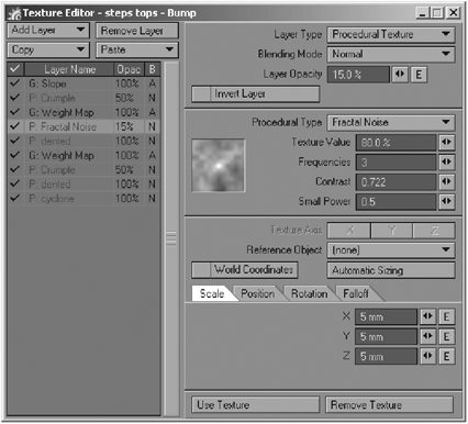
Figure 26-26: Fractal Noise texture
Texture Value: 80%
Frequencies: 3
Contrast: 0.7
Small Power: 0.5
Scale X: 5mm, Y: 5mm, Z: 5mm
39. Since we also want to isolate this texture to the edges, copy the weight map gradient and paste it on top of the Fractal Noise. To finish the bump map, create a Crumple texture (Figure 26-27) with the Opacity at 50%. Also change the following:
Texture Value: 100%
Frequencies: 3
Small Power: 0.98
Scale X: 10mm, Y: 10mm,
Z: 10mm

Figure 26-27: Crumple texture
40. This texture also needs to be isolated, but this time to the sides of steps; to do this use a gradient with the Blending Mode set to Alpha and the Input Parameter set to Slope (Figure 26-28) with the following key values:
Key 1
Value: 0%
Alpha: 100%
Key 2
Value: 77.3%
Alpha: 100%
Parameter: 0.11
Key 3
Value: 100%
Alpha: 100%
Parameter: 0.5
Key 4
Value: 80.3%
Alpha: 100%
Parameter: 0.85
Key 5
Value: 0%
Alpha: 100%
Parameter: 1
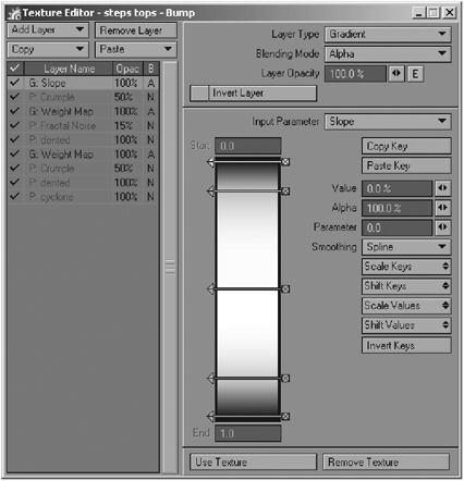
Figure 26-28: Slope gradient
41. The other channels are easy. Change the Specularity channel value to 60% and click on the Specular channel’s “T” button. Change the default texture to a gradient. Since this is a simple white to black gradient, just change the Input Parameter to Bump. For the Glossiness channel, just change its Value to 40%. The Reflectivity channel needs to be at 5% to 8%. It also needs a Turbulence layer with the Opacity at 25% (Figure 26-29) and the following settings:
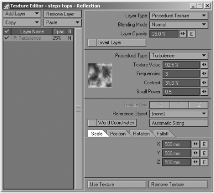
Figure 26-29
Texture Value: 92.5%
Frequencies: 3
Contrast: 31%
Small Power: 0.5
Scale X: 500mm, Y: 500mm, Z: 500mm
You can make a test render or you can use FPrime to see the progress of the texturing work thus far.
42. Back in the Surface Editor, right-click on the “steps tops” surface and copy it; paste this surface to the “chipped wood” surface. All we need to do here is change its color slightly and delete some unneeded texture layers. Make the base color something like 248, 241, 229 to make it look like the geometry dents were at some point painted with the steps, or you can texture them like wood so it looks like the chipped wood is recent. Open the Color texture layers and get rid of the gradient and the Turbulence layer on top of the layer stack; then open the bump layers and get rid of these (bottom to top): the first Crumple and its gradient and the Slope gradient. You should have what’s shown in Figure 26-30.

Figure 26-30: Bump map
43. The “foot guard” surface basically follows the same process as we have done before with a slight difference in color and pattern. Copy the surface “steps tops” and paste it into the “foot guard” surface. Change the color to a light gray, something like RGB 223. The Specularity value should be 30%, Glossiness 40%, and Reflection 3%.
44. Open the Texture Editor for the Color channel and delete the weight map gradient. Select the Dented layer and change its Blending Mode to PShop Multiply, then set the texture color to 138, 129, 117. Copy this layer and paste it on top of the Turbulence layer; since the turbulence texture is set to Displacement, the dented texture will get disturbed and thus make smears and scratches on the surface. Change the Dented layer (Figure 26-31) values to the following:

Figure 26-31
Texture Color: 187, 170, 138
Scale: 1.19
Power: 3.15
Frequency: 1.1
Octaves: 5
Noise Type: Perlin Noise
Scale X: 2m, Y: 2m, Z: 2m
Now open the Bump channel’s Texture Editor to remove some of the unneeded layers. Remove or turn off (from top to bottom) the Slope gradient, Fractal Noise, the weight map gradient, and the other Fractal Noise layer. The Texture Editor should look like the one in Figure 26-32.

Figure 26-32: Bump layers
As I mentioned at the beginning of the chapter, I added a couple of toys to have a little nostalgic and playful feeling in the image. These objects are hidden in the scene; just open the Scene Editor and unhide them, then activate them so the renderer can see them. If you happen to have Worley’s Sasquatch you can load the scene called bear fur.lws included on the companion CD. You can render this pass separately and compose it on top of the finished stairway image. If you don’t have Sasquatch, you can use Saslite, which is included with LightWave. Figure 26-33 shows the final composite I created using Photoshop.

Figure 26-33: Final composite