
Chapter 25
LightWave/ZBrush Workflow
In Chapter 11 I gave you a quick overview of ZBrush’s features. Now I’ll talk about how you can implement ZBrush into your LightWave work so you can take advantage of the displacement maps, normal maps, etc., that are now part of the everyday production pipeline. It might seem at first glance that the steps are quite extensive, but in reality it isn’t that difficult or lengthy. Once you know what to do, it’ll be a breeze, and working with ZBrush is a lot of fun, too. For artists who are new to ZBrush, I recommend getting used to the interface and tools first since ZBrush’s interface is quite different than any other app out there. If you just can’t wait and want to dig right in, then follow along; by the time we are done, you should be able to work with your own models from start to finish. Let’s get to it!
Preparing Your Model for ZBrush
The first thing we need is a model to work from. I have provided a base object of an alien head for you to follow along with (in the TutorialsAlien directory on the companion CD), but you can work with your own model if you prefer. One rule of thumb that you should keep in mind when your model is intended for sculpting and painting in ZBrush is that it is preferable for your model to be all quads. ZBrush subdivides the base object the best when it is all quads. If you find that some triangles cannot be avoided, try to place those triangles in inconspicuous places so if there is any pinching it is not so noticeable. Another “rule” is to cap the holes in your model, such as eye sockets and nostrils. I have left holes in the base object for illustrative purposes; the bottom of the chest will not be seen in our final render, but if you move the camera in Layout you will see a harsh line of the displaced polygons caused by the lack of a cap in the alien bust. I also left the mouth interior out since I wasn’t going to open its mouth. When you are working with your own models, don’t forget to cap the holes.
A last tip about preparation is about the UV layout. ZBrush has some powerful UV tools that make this part of the creation process a breeze; however, I personally like to unwrap the mesh myself in LightWave. I’ll explain why shortly, but for now just remember that if you decide to unwrap your mesh in LightWave, make sure there are no overlapping UVs. If your UV layout has any overlapping UVs, ZBrush may crash upon loading the object, so if you run into this problem take a look at your UV layout first. Taking the time and not rushing through unwrapping pays off at the end.

Figure 25-1: The Alien head base object
We are almost ready to export our freaky-looking alien, but one last thing before we hit the Export button… Open the Surface Editor (F5), and then the Color Texture panel, and in the default layer select the UV texture we created. It doesn’t have to have an actual image; what we are looking for is that the OBJ Exporter recognize that there is a UV texture being exported with the model. If this step is skipped, the UVs will be skipped as well upon exporting.
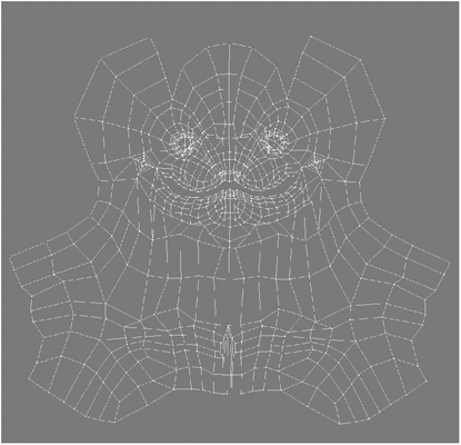
Figure 25-2: The Alien head unwrapped
Now we are ready to export. Create a descriptive folder in your content directory to avoid any confusion. I usually name mine “OBJ” and then save the OBJ file there with something like “base” somewhere in the name; this way you know it is the base object that you exported from Modeler.
TIP: You can take advantage of Modeler’s “parts” in ZBrush since they get exported with the OBJ model. In ZBrush, “parts” will show as polygroups that you can hide on the fly by holding the Ctrl and Shift keys while clicking inside the polygroup you wish to keep on the canvas. Click again while still holding the keys to invert the selection.
Importing Objects into ZBrush
Now that we have our base object completed, it’s time to load it into ZBrush.
Once you open ZBrush, roll your mouse over the Tool menu at the top of the UI. Click on the little orange icon on the far left corner to dock this menu to either the left or right side of the UI. ZBrush calls imported objects “tools” and this is where our object will be after import. Click on the Import button under the Tool menu and browse for the OBJ model we exported; the object will appear as the current tool.
Go ahead and draw the Alien head on the canvas by clicking and dragging. Immediately after drawing the object on the canvas, click on the Edit button right below the main menu. As long as the Edit mode is active, you will be able to modify your mesh in 3D space. The minute you deactivate this button, ZBrush will drop your mesh onto the canvas and it will no longer be an editable 3D object like before. In Edit mode it is “pixols” based, also known as 2.5D. Like I said earlier in the book, pixols are more powerful than regular pixels since they can hold z depth and material information.

Figure 25-3: ZBrush’s UI with our Alien OBJ model
We are not going to experiment with this aspect of ZBrush; just remember to keep the Edit button active and everything will be fine.
On the right side of the UI you will find the tools needed to navigate through the canvas. These tools also have keyboard shortcuts. To move your object, press and hold the Alt key and click and drag your mouse. To rotate the object on its own axis, just click and drag anywhere on the canvas. Scale is a bit trickier. Press Alt, then click and hold on the canvas, and release the Alt key; this might take a little getting used to.
ZBrush’s UV Tools
Let’s explore the UV toolset in ZBrush and see the advantages and disadvantages of their use in our LightWave workflow.
There are many options available in the Tool menu when we have an object active on the canvas. We are going to use several of those options, also called subpanels, but for now let’s look at the Texture panel, which is accessed by clicking on the Tool menu. Here we have the UV tools; the first three from left to right are the common cylindrical (Uvc), planar (Uvp) and spherical (Uvs) projections that by now you should feel comfortable using. The next one, UVTile, will tile the texture image map to every single polygon of your mesh, taking advantage of tileable texture maps. This option works best when the polygons are pretty uniform across the mesh.

Figure 25-4: Texture panel
Next we have the two options that you will use the most when unwrapping meshes in ZBrush: GUVTiles and AUVTiles. Adaptive UV tiles (AUVs) explode the texture into rectangles of the same approximate size. These match the size of each polygon of the mesh, so the more polygons on your mesh, the more tiles in your AUV.
Grouped UV tiles (GUVs) are very similar to AUVs with the biggest difference being that GUVs try to group areas together so it is easier to read if the texture is later opened in an external program such as Photoshop or Painter. I personally like to unwrap my models myself because I end up getting exactly what I need and they are perfectly readable by anyone who takes a look. This might be very important in large studios where a texture might have to be retouched by someone not familiar with ZBrush. If UVs are not your strongest skill, then either one of these two options will do a great job for you.
ZBrush needs UVs in your object for the creation of texture, normal, and displacement maps. If you are sculpting, you do not need to have one right away, but it is good practice. Also, try to use a power of 2 for textures; for example, 256, 512, 1024, 2048, or 4096. The power of 2 is really important when dealing with real-time render engines like those used for video games. A 1000 × 1000 texture map will use as much memory as a 1024 × 1024 map, so why not use the extra pixels? Also, some engines will round the texture to the next size, so if you have a 1050 × 1050 texture the engine will need the same memory as if a 2048 × 2048 texture was used. Of course this greatly depends on the game engine itself, as some engines do let you use odd resolution figures. For textures intended for broadcast and/or film, the issue is not that important. What would be more important is that UV maps are square, and since you are using UV maps to paint your objects, your ZBrush texture map should be square as well; otherwise, you might have unpredictable results.
Our alien head has a UV map already created in Modeler, but if you would like to try the above mentioned UV options by all means do so. You won’t break anything. ;)
Sculpting and Texturing
You have everything ready to start sculpting… well, almost everything. Before you start sculpting your object, go ahead and open the Morph Target subpanel and click on the StoreMT button as shown in Figure 25-5. ZBrush uses a form of hierarchical subdivisions, and you can go up or down the levels of subdivision at any time. Changes done at any particular level of the hierarchy are propagated through all the other levels of subdivision, so if there are major changes to the mesh, level 1 of our base will get deformed as well. The Morph Target helps us go back to the original base object when it is time to generate our displacement maps and normal maps. However, if the changes are extremely drastic, it is better to create the needed maps from level 1. We’ll discuss this in detail later, when we are ready to go back to Modeler. Now let’s get started with the sculpting process!

Figure 25-5: Morph Target subpanel’s StoreMT button
Open the Display properties subpanel and change the DSmooth option to 1. This is like turning smoothing on in the LightWave Surface Editor. At this point you can subdivide your object. I start by working one level at a time first, adding a level when I feel I have gone as far as possible with the current level. Click on the Geometry submenu and click the Divide button to add a subdivision level to the mesh, then sculpt away until you feel that you need another level of subdivision. Remember that the changes to the mesh will propagate through the subdivision levels.
Having a pressure-sensitive graphic tablet like a Wacom, for example, is a great advantage and I strongly recommend it; it makes sculpting and texturing in ZBrush that much more enjoyable.
Sculpting is very intuitive in ZBrush, but you still need to familiarize yourself with the tools right above the canvas area. Let’s just concentrate on those that will allow us to sculpt our mesh. (Remember to keep that Edit button on!) Right next to the Edit button are the Draw, Move, Scale, and Rotate buttons. When you are using Draw, you will be able to paint and/or sculpt your mesh. Move allows you to move vertices very similarly to the Magnet tool in Modeler, where the brush has a falloff and therefore lets you adjust several vertices at once. If you make the size of the brush and its focal shift quite small, you will be able to affect one vertex at a time. The same goes for Scale and Rotate. Notice that some options in this toolbar will be grayed out depending on what mode is active.
This toolbar also contains buttons to turn off or on the channels that you wish to affect: Material + RGB (Mrgb), Rgb (RGB alone), Material (M alone), Zadd, and Zsub. Zadd will add volume to the sculpt, and Zsub will take away volume from the sculpt. These are the two we are going to be using right now. Leave Zadd active and deactivate Rgb or Mrgb if they happen to be on.
Also in this toolbar you will see Z Intensity, which is the strength of the current brush; Focal Shift, which controls the brush’s falloff; and Draw Size, which controls the overall size of the brush. Because these are used quite often, Pixologic created some contextual menus to make changing all these options a snap. Press the “s” key to display a contextual menu from which you can change the brush’s size. If you also need to change other options at the same time, like Size and Focal Shift, then press the Spacebar to open a contextual menu that displays most of the options available on the top toolbar. This increases productivity since you don’t have to break the creative process just to change the focal shift of the brush, for example.
Figure 25-6: The top toolbar buttons and options
Another extremely useful shortcut when you are sculpting is the Alt key. By pressing this key your brush will interactively change modes on the fly; for example, if you are in Zadd mode, the Alt key will switch the mode to Zsub! This is so convenient and is one of those little things that make a huge difference when sculpting.

Figure 25-7: Spacebar contextual menu
While you are sculpting, you will run into some hard edges. These are common and sometimes even desirable, such as when you’re sculpting wrinkles. Press and hold the Shift key to switch your brush to a smoothing brush.
You may reach a point where your mesh has over one million polys and performance suffers a little, even though it’s still quite fast for such a high amount of polys. To get better rates you can hide parts of your mesh momentarily. Remember when I mentioned that parts get saved in the export to OBJ from Modeler? Now we can take advantage of those. Click on the Frame button on the top toolbar and you will see the alien head in wireframe shaded view with two different colors. Those colors are the parts I saved in Modeler; in ZBrush they are called polygroups. This is extremely useful not only because of performance improvement, but also so you can access areas of the mesh that would otherwise be hard to reach or isolate. You can also save your own polygroups right in ZBrush by separating the UV islands of your mesh into groups (if your model happens to have a UV layout, that is). You can also hide the geometry you wish to exclude from the polygroup and then click on the Group Visible button in the Polygroups subpanel.
One thing that I run into a lot in forums is that new users try to sculpt every little miniscule detail on their objects, such as skin pores and tiny wrinkles. I believe that doing so is kind of inefficient and a waste of memory since the mesh needs to be subdivided a lot in order to achieve such fine details and replicating such a high level of detail can be quite difficult and time consuming. It is more efficient to do two passes: a low-frequency sculpt where you sculpt the major changes of the form of the mesh and a high-frequency pass for adding details such as the skin pores as a bump map. The results are excellent and it is far more efficient.

Figure 25-8: Low-frequency sculpt
Texturing is a similar process to sculpting but you usually will work with Zadd or Zsub off, and use Rgb only. As I mentioned before, you need to have UVs present before you start painting. You already know that the alien head provided has a set of UVs, so all you have to do is pick a base color first and then create a texture of the desired size; the new texture will be created and will be filled by the main color on the palette. At this point, ZBrush handles painting like “vertex paint.” You paint the vertices of the mesh, so the higher the level of subdivision, the more information there is and the smoother the stroke. Don’t worry too much about this right now since we are going to use one of the greatest tools of ZBrush to paint: Projection Master!
Projection Master
Projection Master allows you to to paint deformations or textures or both at the same time using all of ZBrush’s tools and specialized brushes, such as the Deco, Blur, Highlighter, and Colorize brushes. Projection Master will temporarily drop your object in 2.5D space to paint and you will not be able to navigate through the object in 3D space; however, Projection Master will compensate for all the deformations and color information painted. After you are done with one side you move on to the next, and so on, until the complete mesh is detailed or painted. Another cool feature of Projection Master is that you can use alphas as brushes and thus paint and deform an incredible amount of detail very quickly. I have included a folder on the companion CD named SNoWs_ZBrush_alphas that contains alphas for you to use. Let’s go through the process of painting deformation details on our alien dude.
Go to the highest level of subdivision in the mesh by moving the SDiv slider on the Geometry subpanel to the far right and then click on the Projection Master button. The Projection Master window pops up. This window is divided in two sections. The top section has to do with color textures and the bottom section has to do with deformation textures. Turn off every color option and turn Deformation on. Once you click on the DROP NOW button, the model will become pixols based until we finish the Projection Master session.

Figure 25-9: Projection Master
Load any of the provided alphas from the companion CD. Set the size and intensity of the brush and make sure Zadd is active. Select a brush from the Tool panel and go crazy! Experimentation is the name of the game at this point. Experiment with different brushes, z intensity, alphas, and strokes and see their effects.
Once you are happy with the results, you are ready to pass all those changes to your actual mesh. Click Projection Master once again; the DROP NOW button now reads PICK UP NOW. Once you hit that button, ZBrush will transfer all that information to your mesh! Easy, right?
The same thing goes for painting textures, but you select the Colors option instead of Deformation. Follow the same steps as before but remember to turn Zadd/Zsub off and turn Rgb on. Again, experiment. Use different colors and alphas, use the Blur brush to blend colors, use the Highlighter, Noise, etc. Go crazy!
TIP: When using Projection Master, stay away from mesh edges. If your brush goes over an edge that is not visible, the texture will get projected through the mesh in a similar fashion as a planar map, causing undesirable stretching or displacement where it was not intended.
Now that we have all the low-frequency deformation and color textures done, we can move on to the high-frequency details. Create another texture filled with a medium gray (128, 128, 128). This will be our high-frequency bump map. Click on the Material ball and load the bumpmatviewer material from the ZMaterials library that comes with ZBrush. This material will be applied to the mesh automatically upon loading and will allow us to view the bump map as it will appear in LightWave when rendered. Drop your mesh in Projection Master and knock yourself out! Pretty cool, right?
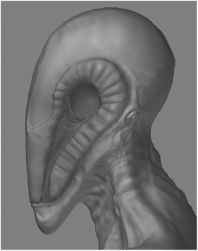
Figure 25-10: Color texture

Figure 25-11: Bump map viewer material
Rendering and Saving Displacement, Normal, and Texture Maps
Well, that’s been fun and all, but we want to go back to LightWave to get our masterpiece rendered.
In order to use all of the texture maps we created, we need to flip the V coordinates of the maps; otherwise, our textures will be mapped incorrectly in our model. This is the most common problem people have when they are starting out incorporating ZBrush into their work. The active texture should be the bump map that we just worked on. Open the Texture panel and dock it. Right below the texture maps is a button labeled Flip V. If you click this button, you will see that the bump map seems to be improperly mapped to your model in ZBrush, but it will show correctly once we load it into Layout. You will have to do this for every texture you save from ZBrush to be used in LightWave. After you flip the bump map, save it as a TIFF or PSD file, whichever you prefer; the file format for bump maps is not as important as it is with displacement maps.
Displacement maps are grayscale maps rendered from the sculpting you painted on your object; essentially they are height maps. This map is then used in Layout to displace the geometry to mimic the ZBrush sculpt.
Let’s get our displacement map rendered out. Go to the first level of subdivision of the alien head model and roll out the Displacement subpanel. Here, you set the algorithm to be used and the resolution of the map. Go ahead and change the DPRes to the maximum, which is 4096 pixels, and turn on SmoothUV. Now you need to select the displacement algorithm. You can select from Adaptive Scan or DPSubPix (subpixel). Adaptive Scan should be fine for most of our work and this is what I used for the final displacement of our alien. The main difference between Adaptive and subpixel is that subpixel calculates the number of times the mesh is subdivided before the displacement map is generated. If you went all out and painted in skin pores, for example, this will give you better results than Adaptive since it is more accurate; however, the render times will be dramatically longer — sometimes several hours longer depending on resolution and the level of accuracy you selected. Since we separated the high frequency from the low frequency, we can use Adaptive and save a lot of time without the quality suffering at all.
Click on the Create DispMap button to render the displacement map. A progress bar will appear, informing you of the progress and estimated time. After the map is rendered, it will show up as the current alpha map in the Alpha panel. If it doesn’t show as the current alpha, click on the Alpha panel and select it; it should be the last image listed in the panel. Now flip this image’s V coordinates and save it as a TIFF file. This is very important since TIFF files saved from ZBrush will be 16-bit per channel instead of 8 like PSD, and therefore will give you greater accuracy and in turn better results.

Figure 25-12: Flip V
Normal maps are very similar to bump maps, which are used to add detail without adding more polygons to your geometry. They contain more data and thus provide better results, and they can completely replace the normals of the polygons. Open the Normal Map subpanel in the Tool panel and turn on SmoothUV and Tangent, which is necessary for LightWave v9. Click on the Create NormalMap button to render the map and the progress bar will come up again. After the map is rendered, it will show as the current texture; once again you will flip the V coordinates and save it as a TIFF.
If you have painted any other maps, such as specular and diffuse maps, flip and save those as well. They do not need to be TIFF 16-bit and can be saved in PSD format. All of these images will be opened in Photoshop or your image editing software of choice to be converted to PNG format images. PNG will keep file sizes small without sacrificing their quality. Keep the displacement and normal maps as they are; do not convert them to PNG or you will lose the extra data saved in a 16-bit file like those we saved from ZBrush.
At this point export the level 1 object as an OBJ file. We will bring this into Modeler to prep it for Layout.
Bringing It All Together
Open the original LightWave object and the newly created object. Since our object had major changes I decided to go with the level 1 mesh from ZBrush, but there is one slight problem — our original mesh contained vertex data since it had a morph map. We lost this morph map when we exported the model for ZBrush. Don’t worry, though, we just need to pass the vertex position of the new object to the original model so we do not have to recreate every morph map. Copy the object from ZBrush and paste it in a new layer of the original object. We are going to use a Modeler tool called Background to Morph. This is a snap since the vertex order has not been changed; if the vertex order had changed at all, then I’m afraid there is no recourse but to redo all your morphs, weights, etc. Luckily, we don’t have to deal with that because we did not add or subtract geometry to the base object.
Make the original object the foreground and the ZBrush object the background layer, then go to Map>Morph and select Bkg to Morph, pick a name, and click OK. Now that we have a morph of the new vertex locations we need to pass this data to the base object. Go to Map>Morph, choose Apply Morph, and make sure you select the correct morph map since every vertex map you have in the file will be listed here. Then click OK, and you’re done! All the vertices are now in the identical positions as the base exported from ZBrush. Hit the Tab key to convert your object to subdivision surfaces, and delete the ZBrush OBJ layer and the morph map we just created to keep the file clean and tidy. That’s it.
Since we created our UV map right in LightWave, the base object already had it and we didn’t have to pass that information over. If you have a ZBrush-generated UV map, then that has to get transferred to the original base object. To do this we need a free plug-in called ZWave, which you can download from www.flay.com. Install the plug-in like any other plug-in in LightWave, and it will show up in the Additional list. This plug-in is quite easy to use. Just load the original object, the one you want to copy the UVs to, and activate ZWave. Click on the Import File button and browse for the ZBrush exported object. Leave every option as is, making sure that Replace Existing Texture is on, and click OK; the UV data is transferred to the object! Now it’s time to jump to Layout.

Figure 25-13

Figure 25-14: Finished SubD model
Launch Layout and load the scene called Alien_Start.lws. This scene has the object already loaded and ready for displacement and texturing. We are going to use the Node Editor to set up our displacement and texture maps.
NOTE: For more information about the Node Editor, refer to Chapter 14, “The Node Editor.”
First let’s get our displacement map working and matched as close as possible to the ZBrush sculpt. Select the object and open the Object Properties panel (“p”). In the Geometry tab, change Subdivision Order to after bones. We are going to revisit this in a minute. Click on the Deform tab and under Add Displacement, select Morph Mixer, then apply the only morph map available in the list. Now we can see that our morphs are still there and working properly. Click the check box next to Edit Nodes to activate nodes and then open the editor by clicking on the Edit Nodes button. If you are unfamiliar with nodes and you don’t want to go back to Chapter 14, just follow these steps and you will be fine.
Upon opening the Node Editor window, we see a node already there. This is the destination node. In this case it is a displacement node; we will be plugging our displacement network here. Go to the Add Node drop-down menu at the upper-left of the window and add the following nodes:
2D Textures>Image
Math>Scalar>Subtract
Math>Scalar>Multiply
Math>Vector>Scale
Spot>Spot Info
Double-click the Image node and load the displacement image you saved earlier or load the one provided on the companion CD called Alien_sculpt_ disp.tif. Turn MipMap Quality to Off and under Mapping select UV map and pick Alien; this is our UV map that we used to paint our displacement, normal, and color maps in ZBrush.
ZBrush, unlike LightWave, uses 50% gray as no displacement. We need to change these values for LightWave to displace the mesh properly; to do this we use the Subtract node. Connect the Luma output of the Image node to the A input of the Subtract node, then double-click this node to view its properties and change the B value to 0.5. That will take care of the displacement values; now we move on to the amount of displacement. Plug the Result output of the Subtract node to the A input of the Multiply node. Open its properties by double-clicking on it, and then change the B value to 1.5. This number is dependent on the scale of the object; since our Alien head is quite big, let’s start with 1.5 and fine-tune from there.
We now need to tell LightWave the direction and scale we want the displacement to have. We already have the scale figured out using the Subtract and Multiply nodes, so all we need is the direction, which the Spot Info node will give us. We then need to combine the direction with scale, which is the function of our Scale node. Plug the Normal output of the Spot Info node to the Vector input of the Scale node, then plug the output of the Multiply node to the Scale input of the Scale node. The output of the Scale node is then plugged to the input of the Displacement node and our network is finished. You should be able to see the displaced mesh in your viewport.

Figure 25-15: Displacement node network
In order to get as close as possible to the ZBrush sculpt we need to add more subdivisions to the mesh, but instead of doing that globally we will take advantage of APS (Adaptive Pixel Subdivision). With APS we can tell the LightWave render where more detail is needed and where it is not that crucial, so let’s revisit the Object Properties panel and make some changes.
In the Geometry tab in the Object Properties panel, change Render SubPatch to Per Polygon Level and click on the “T” button to open the Texture Editor.

Figure 25-16: APS
Here we are going to create a gradient with three keys that will control the density of the mesh. Change the value of the first key to 25, make another key and place it on the bottom of the gradient, then make a third key and change its value to 0 and place it on the middle of the gradient.
Now you can make a test render to compare your LightWave output to the ZBrush sculpt. After the test I felt I needed to increase the amount of displacement, so in the displacement Node Editor I changed the amount of displacement from 1.5 to 1.75; the results look closer to the ZBrush sculpt at this amount.
Almost done… Open the Texture Editor (F5) and open the Node Editor, making sure that the check box is on. Here you will see the Surface destination node, which is where we are going to plug in the other textures we created in ZBrush.
Create the following nodes:
2D Textures>Image
2D Textures>NormalMap
Load the color texture in the image map like we did with the displacement map. Make sure MipMap Quality is off and that you select the Alien UVs. Do the same for the Normal Map node but load the normal map we created in ZBrush. Copy and paste the color texture image node and replace the image with the specular, bump, and any other textures you may have. Plug the Color output of the color texture image node to the Color input of the Surface destination node. Plug the Normal output of the Normal node to the Normal input of the Surface destination node, and so on, until all your textures are properly mapped to the corresponding input.
Render again. All the textures should show properly on the rendered image with the exception of the bump map, which is very faint. This is due to the mid-gray ZBrush values again. In order to correct this, just increase the Bump Amplitude in the image node that contains the bump map to a very large amount, like 300% or 400%. Now it is just a matter of fine-tuning the specular, glossiness, diffuse, etc., values as needed. You can even add subsurface scattering or any other type of shaders. Experiment!
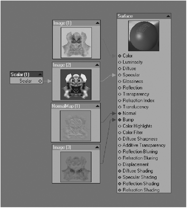
Figure 25-17: Finished skin node network

Figure 25-18: The result
NOTE: Check out Chapter 14, “The Node Editor,” for more on creating networks, shaders, SSS, etc.
NOTE: For more on LightWave and ZBrush workflow and techniques I suggest you read the LightWave ZPipeline guide published by Pixologic and written by fellow artist and author Steve Warner. It has some more cool information that I’m sure you will find useful as well. It can be found at http://www.zbrushcentral.com as well as www.pixologic.com.
ZBrush is an extremely powerful application. By combining it with LightWave, you will be able to create stunning characters, landscapes, planets, meteors, and more!
Figure 25-19 shows a comp I created in Photoshop after playing with the node network a little further. If you would like to use this surface, just load it from the Surface Presets folder on the companion CD or load up the scene called Alien_finished.lws.
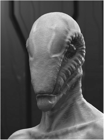
Figure 25-19