
Chapter 17
Map Transformation and Editing Tools
UV Map Editing Tools
Of course, creating UV maps is not just about unwrapping the model and taking it into Photoshop (or whatever paint package you are using). The majority of the time that you spend on UV maps is spent on editing the darn things so that they are actually usable. Once we have made a new UV map, we look to the UV tools in Modeler to start fixing up the stretching and weird distortion that invariably creeps into your unwrapped template.
All the tools that we need are found within the menu under the Map tab in Modeler.
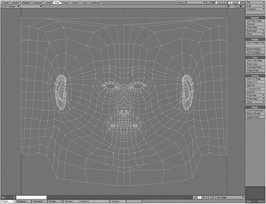
Figure 17-1
Not all of the options we find here are for UV maps, as this tab is for working with all vertex maps, of which UV maps are only one particular type. So if you find yourself wondering why I have ignored some of the buttons on this panel, now you know. This chapter only deals with UV mapping tools.
General Commands
The first bunch of options we encounter under the Map tab are basically just the usual Copy, Delete, and Rename functions that we are accustomed to elsewhere in the LightWave package, as well as a couple of other, perhaps unfamiliar terms. You can click on the Edit Maps and More buttons to access a few other commands as well.

Figure 17-2
Let’s look at each of them, one by one.
Set Map Value
To use this function, you need to select points within your currently active UV map (the one that is showing in your UV map viewport). By selecting points and entering in any U or V value, those points will be moved to those coordinates within the UV map.

Figure 17-3
The first value represents the U coordinate, while the second value represents the V coordinate.
This is great for fine-tuning your UV maps, especially if there is any fragmentation (such as the fragmentation that occurs in atlas maps) and you need to place points back together with a high level of precision. I use this tool a lot when editing UV maps.
Copy Vertex Map
Click on the Edit Maps button to access this command. This option copies the currently selected UV map, just as its name suggests. Copying a UV map creates a new one that you can name as you wish.

Figure 17-4
You can use this option to create one big UV map from a bunch of different maps that you have already made. Simply select the maps one by one, and when the Copy Vertex Map window pops up, simply enter in the name of the UV map that you wish to copy it to. This is useful for when you are working with models like game models, where you are limited to the number of images that you can use on a character, so you can unwrap all the different parts separately and then simply put them all together in a single map and arrange them so that you can texture all the different parts in a single image.
Delete Vertex Map
Click on the Edit Maps button to access this command. This option deletes the currently selected UV map. Use this one cautiously as there is no further prompting to confirm the deletion.
Rename Vertex Map
Click on the Edit Maps button to access this command. Use this option to rename the currently selected UV map. A new window pops up for you to enter in the new name.

Figure 17-5
Clear Map
If you wish to remove certain polygons from within a UV map, use this option. Simply select the polygons that you wish to remove, and press this button.
If no polygons are selected, the entire contents of the UV map are removed.
Be aware that due to the nature of UV maps, removing polygons from the map removes the immediately surrounding polygons as well. Be sure to unweld (Ctrl+u) the points in the map before using this if you wish to keep all the surrounding polygons intact within the map. Just don’t forget to remerge the points again afterward by pressing “m.”
Cull Map
Click on the More button to access this command. Since I have absolutely no mathematical abilities whatsoever (I can barely count over 10), I have a little trouble really fully understanding this tool’s function and usefulness since the explanation of it in the LightWave manual left my brain reeling somewhat.
However, after researching it a little, I have a decent explanation of it for you. This tool affects points in a region of your UV map that you specify by entering in a value for the Threshold Magnitude setting below which all points will be selected or deselected, depending on which option you choose.
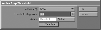
Figure 17-6
This value is reached by using a calculation to determine the region that will be affected by the action, namely the addition of the square root of the U value to the square root of the V value.
All that said though, I have never used this option! When I want to remove points or polygons from a UV map, I generally just select them and hit Clear. It’s more straightforward.
Normalize Map
Click on the More button to access this command. This function scales the selected vertex map from the Source VMap list according to the Minimum and Maximum values specified in the respective fields.

Figure 17-7
This is handy for ensuring that the map makes the most of the UV map space provided. I usually just scale this by hand, as I sometimes want to have different areas in a UV map scaled according to how I want to paint them later on, but this can save you time if it is a simple projection that you have been editing, and you now want to simply size up to fill the space with the touch of a single button. Just be careful that it does not distort any areas that shouldn’t be distorted (although this isn’t all that likely to happen).
Using the UV Mapping Tools
Under the Texture heading on the Map tab, we find the tools for creating and editing our UV maps for texturing.
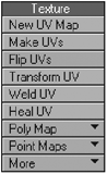
Figure 17-8
New UV Map
This particular function creates a brand new UV map for the currently selected polygons or object in Modeler.
Clicking on the button opens a window from which you select your projection, name your new map, and specify a few other options.
From the Map Type drop-down, you can select the type of projection that you wish to use for your UV map. For more information on each of these projection types, take a look at Chapter 15.
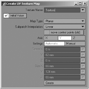
Figure 17-9
Next we have the Subpatch Interpolation drop-down. Here you have some options to help you with distortion of textures on SubD objects. See “Fixing the Annoying Subdivision Distortion Problem — Interpolation Options” later in this chapter for more information about the options in this drop-down menu.
Once you have selected a type of projection and a method from the Subpatch Interpolation drop-down, select the axis that you wish to apply that projection along by clicking on the desired axis button.
Below the interpolation options is a button called “move control points (old)” that is used to turn on or off the “classic” way LightWave worked with subpatched UVs. I supposed that’s there for backward compatibility because I still haven’t found a use for this option in my daily work, but there you have it if you need it for any reason. Just be warned that unlike the interpolation options, this is one you cannot turn on or off interactively; if you don’t like the results, you’ll have to start over.
You can have your UV settings automatically calculated for you, or you can manually enter your own settings for the placement and scale of the UV map by clicking on the Manual button next to Settings and entering your own values. Since you can edit your UV map once it is made, changing these settings is not always necessary.
Make UVs — Assign UV Coordinates
Another way of creating a UV map is to click on the Make UVs button. This brings up a window similar to the one you get when selecting the New UV Map button. Apart from creating new UV maps with this command, you can also use it to edit the settings of an existing UV map by selecting that particular map from the Texture Name list, which lists all UV maps currently assigned to that model.
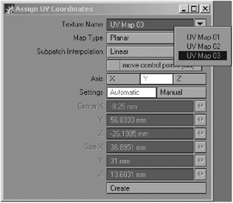
Figure 17-10
This allows you to change the projection type, axis, scale, and position of the existing UV map, which can be particularly useful if you created that UV map without using the Initial Value option in the Create UV Texture Map window.
The Make UVs command can also be used to add additional polygons to an existing UV map. Select the polygons you wish to add to the map, click on Make UVs, and select the map’s name from the Texture Name list.
This is a useful way of making a single UV map out of a few maps without using the Copy Map command.
In this window you also have the option to select an interpolation method for your UVs.
Flip UVs
This command is needed on occasions where, for whatever reason, you have polygons that are facing the wrong way in your UV map. You can flip the polygon along the U (horizontal) or V (vertical) plane, or both.

Figure 17-11
Generally, it is advisable to unweld your vertices before using this command since it can mess around with the discontinuous nature of UV maps.
When using the Atlas unwrap command, it is quite common for polygons to have some of their polygons flipped incorrectly, so instead of carefully selecting points and flipping them manually and then trying to carefully reposition them, using this command saves you time and effort.
Transform UV
Clicking on the Transform UV button brings up a panel from which you can numerically adjust the Offset, Scale, and Rotation values around a specified Center of your currently active UV map.
Remember that UV values are defined by percentage values from within the UV space, so you would enter values from 0% to 100% for these options. Use the Center value to define the point from which these values are calculated. By default, the Center value is 0% for both U and V coordinates, which means that all Offset, Scale, and Rotation values will be calculated from the lower left-hand corner of the UV map outward. If you wish to make these changes from the actual center of the UV map, you would enter values of 50% for both U and V in the Center fields.

Figure 17-12
I don’t ever use this command, since I have a tendency to do everything by hand as much as I can when editing my UV maps.
Weld UV
Weld UV will evaluate the points in the UV map and determine which points are on top of each other and then weld them. This is useful when you have several detached pieces that you move into place and wish to join them with the other pieces (or islands) of the map. For example, if you detach a portion of the UV map mesh using Free Move you will notice that the points of the outer edges will become red on both the section you detached and the mesh you detach it from. If for some reason you want to place it back where it was without using Undo, just move the piece back; the red points will subtly snap, and you can then use Weld UV to make the separated pieces one single mesh again.
Heal UV
Using this tool is similar to sewing points back together automatically. It is important to note that Heal UV averages the position of the offending discontinuous points and will place the continuous points in that averaged location. Use this tool with caution; if you run it on your whole UV mesh, it might jumble it all up. I have rarely used this tool.
Poly Map
As these options are no longer used, they are not discussed here.
Point Maps
Looking under the Point Maps drop-down, we find two commands — Spread UVs and Quantize UVs.
Spread UVs works with quads (four-sided polygons) only, and basically allows you to size them by using numeric values within the UV space.

Figure 17-13
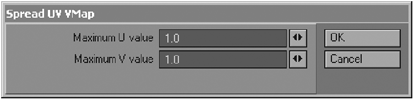
Figure 17-14
The Quantize UVs command snaps selected points in the UV map to the grid using the values entered into the appropriate fields.

Figure 17-15
Again, these are options that I never really use. In fact, I don’t think I have ever used them because of my tendency to eyeball everything and move points around by hand.
Set UV Value
This command is accessed from the More drop-down. The Set UV tool is for numerically positioning points within the currently active UV map. It basically does the same thing as the Set Map Value command we looked at earlier except that this tool is specifically for UV maps, so you have options for entering in values for U and V instead of X, Y, and Z as with the Set Map Value command.

Figure 17-16
This tool is particularly useful for ensuring that points meet where they are supposed to when you’ve been editing a UV map with the points unwelded.
Click on either the U or the V button and enter a desired percentage value within the UV space onto which you would like to position the selected points. This is a very useful tool for precision, especially in those pesky UV maps where things have become horribly fractured (such as an atlas UV map).
Polygon Normal UVs
This command is accessed from the More drop-down. The command projects the texture UVs along the polygon normals, mapping the image flat on the normal.

Figure 17-17
It is a tool that works with poly maps, which is the predecessor to the discontinuous UV maps that we work with now. Since we don’t really need poly maps anymore, this tool (along with the other poly map tools) has really outgrown its usefulness, and I am guessing that the only reason it is still in the program is for the off chance that you may happen to be given a really old LightWave model to work with that uses them. Otherwise, you can ignore it.
UV Spider
This command is accessed from the More drop-down menu. When you select a polygon, the UV Spider crawls along and adds a row of polygons to the UV map. The UV Spider tool is similar in a way to the BandSaw modeling tool.
The following image shows the result of using the UV Spider tool. Two polygons were selected and the tool was activated. In the UV viewport you can now see the entire row (edge loop) of polygons following those selected polygons has been added into the UV map.

Figure 17-18
You will notice that the polygons are stretched to fill the entire space of the UV map, but this can be adjusted using the settings for the tool.
At the top of the panel, where it says Vertex Map, you can enter a new name to create a new UV map for the tool to work with, or you can select an existing UV map to which the UV Spider will add its unwrapped polygons.
The Select Edge options allow you to specify the direction along the actual topography (the model’s surface) that the UV Spider runs along. Selecting Auto will let the tool decide for you.
The Direction option (either U or V) determines the actual direction within the UV space that the polygons will be added to the UV map. If the Direction is U, the band stretches in the U direction (horizontally in UV space) with a top and bottom in the UV plane determined by the U Start and U End values.
The following image shows the UV Spider applied along the U direction with the default U Start and U End values, which stretches the band of polygons across the entire UV space.

Figure 17-19: UV Spider applied along the U direction
If the Direction is V, then the band goes in the V direction (vertically in UV space), using the V Start and V End values to determine the beginning and ending values for the scaling of the polygons in the map.
This next image shows the UV Spider applied along the V direction with the default V Start and V End values, which stretches the band of polygons across the entire UV space.

Figure 17-20: UV Spider applied along the V direction
This tool is quite useful for additional control when unwrapping edge loops (loops of polygons used when modeling organic surfaces), although in some cases you may find it a little more time consuming than using a regular projection.
Guess Viewport UV Image
This command is accessed from the More drop-down. To use it you should have the surface of which the currently active UV map is a part selected in the Surface Editor. Selecting Guess Viewport UV Image then lets Modeler attempt to guess the appropriate backdrop image for the UV map (to be placed as a backdrop in the UV viewport) by looking for the image that the UV map is projecting in the surface.
Figure 17-21 shows the result of this action when working with a skin texture applied using the UV map. As you can see, the command has placed the painted head texture into the backdrop of the UV viewport.

Figure 17-21
This is very useful for making adjustments to the UV map when you need to be able to see the actual image applied while editing, especially when matching a UV map to a premade texture. This option is basically the same as going to your display options, going to the Backdrop tab, and loading the image in there; it simply saves you that effort.
Texture Guide
Click on the More button to access Texture Guide, an interactive tool for creating texture projections on your model. This tool can adjust existing standard projections, as well as create UV maps from them.

Figure 17-22
To use the Texture Guide, you should have the surface that you wish to work with already selected in the Surface Editor, and generally it makes sense to already have an image applied to the surface. Select the Texture Guide tool and press “n” to open its numeric panel so that you can adjust the settings.
It is very much like a more interactive version of the options that you find within the Texture Editor in the Surface Editor itself.
You can select your projection type, adjust the axis along which the image is projected, and alter its scale, position, and rotation. Adjusting the position and rotation of an image is made simpler by the appearance of a bounding box shape with a crosshair in your viewport that shows the shape and size of the image (with the crosshair in the center), as well as the rotation of the image.

Figure 17-23
Clicking on the Make UVs button and entering a name for the new UV map allows you to see, in real time, what the resulting UV map will look like in your UV viewport.
If a UV map has already been created for the object, the Texture Guide can sample the projection into the UV map interactively. This can greatly increase the speed of creating your initial UV projections since you can immediately see what the resulting map will look like.
I never really use this tool, as I am so familiar with the projections that LightWave has, and so I generally know what to expect when selecting the New UV Map option and choosing a projection type. However, this tool is useful for those of you who are still getting a grip on different projections and want a more intuitive method of working with them. But chances are that you will eventually outgrow this tool once you become a UV mapping expert!
Tips for Editing UV Maps Successfully
The Necessity of Editing UV Maps
If I had a dime for every occasion that someone has told me, “I don’t understand UV mapping,” I’d probably have … well, a lot of dimes. In all honesty I am not sure why it is that people struggle so much to understand the concepts of UV mapping when they are actually so very simple. All you need to do is use your brain. If you can make a model in 3D, then you certainly have enough brainpower to handle UV mapping properly, trust me.
As I have mentioned before, one of the really handy things about using UV maps, as opposed to using standard projection techniques to apply your textures to your models, is that UV maps can be edited. This means that you have vertex-level control over the exact placement of your textures since you can adjust the map to suit your needs. Essentially, you can create a UV map using any particular axis and projection type, and with time and effort you can adjust it to look completely different.
Take a look at the following image. As you can see, the unwrapped map of this armor (done along the y-axis using a Cylindrical projection) would be difficult to use as a template for a texture because, well, frankly it’s a little crazy.

Figure 17-24
This was an armor model I made for an elf character, and I wanted to paint very intricate patterns onto the armor plating. Because of this, I needed to find a more ideal way of laying out the UV map so that the process of painting patterns would be simplest. I decided to edit the UV map so that each of the strips of armor formed a horizontal band that would be easy to paint rows of patterns onto.
After a bit of tweaking I ended up with the following map instead, a far more convenient layout onto which I could paint patterns.
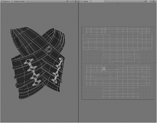
Figure 17-25
In doing so, I’ve also eliminated all the overlapping polygons, which cause problems once a texture is applied. Overlapping polygons are one of the biggest reasons for editing UV maps, since most UV maps that you create, especially for organic surfaces, will initially have overlapping polygons appearing in certain areas.
This very clearly illustrates the benefits of taking some time to edit your UV maps to make the process of painting your textures so much simpler and straightforward.
But before we look at the actual nitty-gritty of editing UV maps, it’s important to understand how UV maps in LightWave actually work.
Understanding Discontinuous UV Maps
UV maps in LightWave are created in a discontinuous manner. This means that when the polygons are unwrapped and flattened to create the UV map, areas where the model has become “split” by the unwrapping process will remain locked in place to ensure that they do not become very badly misaligned during the editing process.
When you try to select all the vertices within the UV map, only a certain number of them can be selected.
In previous versions of LightWave, these vertices could not be selected or even be seen in the UV Editor at all.
The reason the vertices can not be selected or seen is because they are essentially attached to one another on the model itself, despite being in different places within the UV map.
In the following image, I have selected two polygons that are directly alongside each other on the model. However, as you can see, in the UV map they are on opposite sides, and because of that, the polygon on the top right has no selectable vertices in the UV map because those particular corners are joined to other polygons where the points are selectable.

Figure 17-26
Since these polygons are all connected to each other, what will happen if I select that polygon marked “1” and try to move it within the UV map? Take a look at Figure 17-27. I’ve added the arrow to show the direction in which I tried to move the polygon.
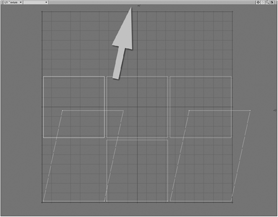
Figure 17-27
As you can see, the polygon I selected cannot actually be moved within the UV map because its vertices are locked to the polygons to which it is selected. And it is the polygons to which it is selected that move instead. This demonstrates the discontinuous nature of the UV map.
Starting with version 8.5, however, you can see the vertices in a discontinuous UV map and you can also edit them! Once you open the UV Editor and you have a map made you will notice some red points on your map which are the shared vertices of the discontinuous map. Having those points in red makes it easier to see where the seam is within that map. Just make sure that the vertices of the seam match up for a good, clean map.
Using the Unweld Command
While this discontinuous property of UV maps can be useful to remind you where the seams lie within a UV map, you will probably find that most of the time you’ll want to work without this happening, since you invariably want to be able to shift around all the points you need to when editing your maps.
Thankfully, we now have a new option to help with this problem! When you enter the UV Editor you will now see a button called Free Move on the top navigation bar, which when activated will allow you to edit vertices and polygons whether you are in SubD mode or not. This helps tremendously when editing UVs. You can select a group of polygons and move them to a different area of the UV map without having to unweld first, a huge time saver.
While we now have the Free Move option to help with discontinuous UV maps, you will occasionally get in a situation where unwelding the vertices would be a better solution.
Unweld (Ctrl+u, or Detail>Points>Unweld) will disconnect the polygons within your UV map from one another while maintaining the points that connect them on each polygon. The points are duplicate copies of those selected points (or of all the points in the model if none are selected) so that none are shared by two polygons.
Each polygon is given its own copy of the selected vertices, and VMap values for the polygon are made continuous over the new vertices. This command is essential to being able to edit discontinuous UVs correctly and efficiently when Free Move alone won’t do. For example, if you are editing a UV map with Free Move activated, you might see interconnecting lines due to the nature of discontinuous UVs. A better solution for this case would be to make a new set of UV maps for each part you are mapping and merge them all together using the Copy Vertex Map command, as discussed earlier, or simply unwelding your mesh, so keep this technique in mind every time you are editing UV maps.
Just remember to merge (press “m” or Construct>Reduce>Merge Points) the points again once you are finished editing! If you have moved points around in the map that were previously discontinuous, merging the points will keep the changes you have made. This is useful since it allows you to place seams where you want them.
NOTE: Separated groups of polygons in the UV Editor are also known as “islands.”
Fixing the Annoying Subdivision Distortion Problem — Interpolation Options
Many LightWave users, especially the seasoned ones, know about this “little” problem that LightWave’s subdivision surfaces have had since their introduction. When UV mapping subdivision surfaces in Modeler, you would encounter a strange phenomenon whereby you find little distortions on your surface when applying textures with UV maps. While some of the distortions might be visually inconspicuous once the texture had been applied to the model, these distortions were sometimes quite obvious, such as when your texture is required to have lines, logos, or letters. This could be quite frustrating and annoying to solve.
Figure 17-28 shows examples of this distortion. I have circled some of the areas affected by this problem, and as you can see, the texture has little jiggles in it in these areas.
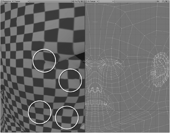
Figure 17-28
In the past we used to have workarounds to help reduce this distortion, including increasing the poly count, but as you know, by doing so you would also be increasing physical size and render times. You could also use morph maps or endomorphs to help alleviate the problem. Of course the last method of dealing with highly problematic situations is simply to opt for using standard projections instead of UV maps.
To correct this problem, LightWave now has Subdivision Interpolation options from which you can select the most appropriate method for your mesh. These options are accessible when you create a new map via the New UV Map button, the Make UVs button, or the Vertex Maps window. You can also customize the Map tab of your GUI and add the interpolation buttons to the UV Texture group of buttons. You can select from the following options:
• Linear — This option is most frequently used when you are creating UVs for polygonal objects. Since there is no smoothing of the geometry like in SubD models, the interpolation is calculated in a linear fashion, point A to point B. Some users like to unwrap their SubD objects while in Polygon mode; however, you will get somewhat less distortion if you unwrap your SubD models while in SubD mode, which leads us to the next option.
• Subpatch — This one is a godsend. This option practically eliminates distortion of your textures on SubD models. I say practically because some distortion may still occur, but it is most likely due to texture stretching or overlapping UVs than the actual conversion from polys to SubDs. LightWave used to have only one method of UV interpolation, Linear, so when you converted your polygons to SubD, the interpolation solution wouldn’t take into account the smoothing of the polygons; it would still calculate from point A to point B, ignoring the curve between these two points, and therefore distortion would occur. With this option, the interpolation between points will be weighted, as if the UV mesh was a SubD mesh as well, taking into account the smoothed geometry of a subdivision surface and thus solving the annoying distortion problem. It is also important to mention that the discontinuous edges that you might have will not be aligned.
• Linear Corners — This option will interpolate the corners of the mesh and the pieces you separate using Free Move. The edges between these corner points get Subpatch interpolation. The discontinuous edges do not line up with this option either.
• Linear Edges — Very similar to Linear Corners, the main difference is that the corners and the edges in between get interpolated linearly. The discontinuous edges will meet up, but distortion might still happen as a result.
• Across Discontinuous Edges — This option is very similar to Subpatch with the biggest difference being that unlike Subpatch, the discontinuous edges will line up, thus decreasing the distortion on the discontinuous edge. I usually stick to this option or Subpatch for all my SubD meshes.
When you have the UV Editor open and a UV set selected, you can change between these options interactively and see their effect in the viewports. You can do this with the Vertex Maps window or by adding the buttons to the GUI, as I described earlier. You can also assign wireframe colors to different UV maps, making it easier to tell what’s what in the viewport when more than one UV set is selected.
Eliminating Stretching
For most organic models, as well as some nonorganic ones, you are going to encounter a certain degree of stretching when creating UV maps. This is simply because the unwrapping process is bound to make some changes to the sizes of some of the polygons when it lays them out flat. One of the best ways to check how much stretching is occurring in your map is to apply an image with a checkerboard pattern to the model using the UV map. This immediately shows you where the map is stretching or pinching.
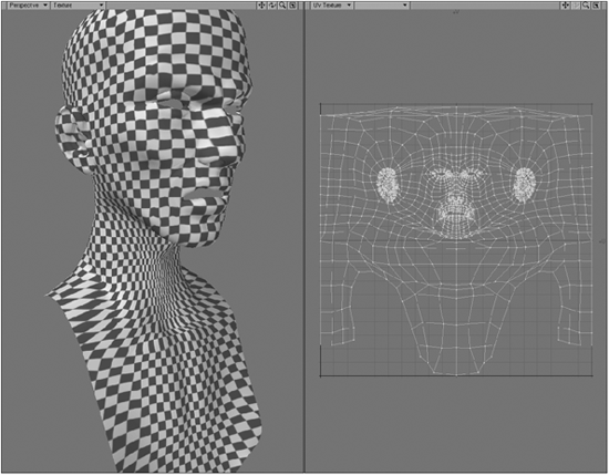
Figure 17-29
Eliminating this stretching is generally quite straightforward. All we need to do is go to those areas of the UV map and push and pull the vertices around in order to size the stretched polygons correctly in relation to the other polygons.
Interestingly enough, this way of eliminating stretching requires you to almost think backward. This is because the way that you move vertices to eliminate it is actually opposite to what may seem logical to you.
For example, let’s look at the following area on this unwrapped head, where we can see a lot of stretching occurring.
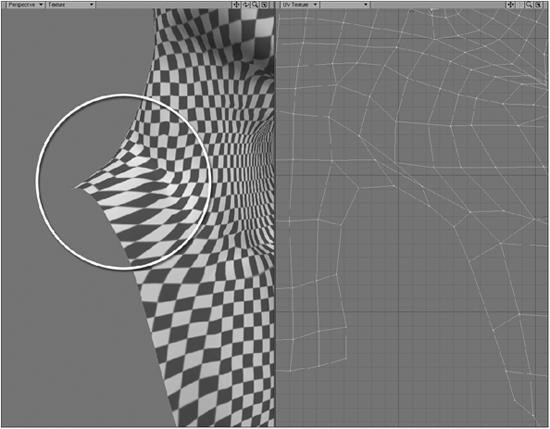
Figure 17-30
The reason that I say we need to think backward is because stretching in a UV map does not occur because the texture is stretched over too many polygons (as would seem logical to those of you who are not UV-savvy), but because the texture is actually stretched over too few.
Let’s look again at the model, and focus specifically on the areas where the stretching is particularly bad. I have circled the polygons in the UV map where the stretching is occurring.

Figure 17-31
Now, the reason that this area is stretching so badly is because the little checks in the image are being stretched over too small an area within the polygons in the UV map. A good analogy to describe this is that the polygons in the UV map basically act as a container into which that particular portion of the image that lies beneath it fits. Sometimes we need to adjust the size of that “container” in order to allow more of the image to fit into it, and sometimes we need to adjust it so that less of the image fits into it, and instead overflows into the surrounding “containers.”
So what we need to do to fix this is to stretch the polygons in the UV map outward so that more of the image is contained within them, instead of a small area of it being stretched to fit inside the polygons.

Figure 17-32
Likewise, in areas where the texture is being squashed, as shown in Figure 17-33, we need to do the opposite to eliminate it, since essentially the squashing is caused by too much of the image being put into the “containers” of the polygons.
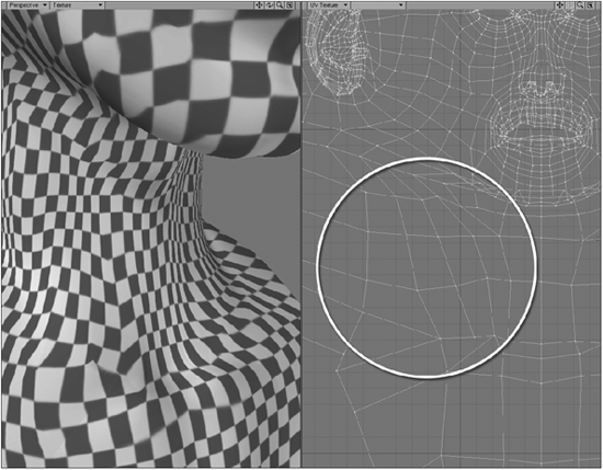
Figure 17-33
So in a case like this, we simply push the polygons in the UV map inward so that the image overflows into the surrounding polygons instead. In doing so we have less of the image fitting into the polygon.
Basically, we need to look at the sizes of the polygons in the actual model, and ensure that they are relatively proportional to one another within the UV map as well. This is probably the most time-consuming part of editing UV maps.
Combining Different UV Maps
Sometimes you may have a number of different UV maps assigned to a single model that you wish to combine into one UV map once they have all been created. This is something that is particularly common when working with game models, since it means that you can essentially apply textures to an entire character using a single image.
To do this in LightWave, you can start off by making as many different UV maps as you like and then making one final one into which you will combine all the maps already created. When you make the final map, click on the New UV Map button and simply deselect the Initial Value option in the Create UV Texture Map window. This creates a blank UV map.
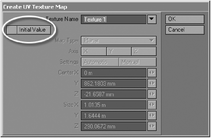
Figure 17-34
Of course, you don’t necessarily have to make a new map. You could just take one of the existing maps and combine all the others into that one. But for the sake of example, let’s just use the new blank map.
To get all the UV maps into the single map, all you need to do is use the Copy Vertex Map command, found in the Edit Maps drop-down list.
Go to each of the maps that you have made, click on the Copy Vertex Map option, and in the text field in the window that pops up, simply type in the name of the blank map that you created.

Figure 17-35
Doing this to each of the maps you have created will add the information from each UV map into the one whose name you enter into the text field when copying them.
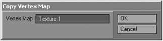
Figure 17-36
Eventually you will end up with a nice big UV map that contains all the maps for your character, which you can then go into and size and arrange each part to suit your needs.
Patience
The most important thing you need to have when working with UV maps, apart from using your brain, is a lot of patience. And I’m not talking about the card game.
UV mapping is almost always a fairly time-consuming process, but in the end it’s generally worth it since working with a well-edited UV map makes the process of painting textures a lot smoother and more enjoyable because you don’t have to worry about stretching or distortion issues when you finally apply your beautifully painted textures to your model. Getting a great UV map can take one hour, or it can take ten hours. Sometimes even more. The more you get used to it, the quicker the process will become as you refine your techniques and habits, but you will still find yourself occasionally sitting for hours on a single map. Just grin and bear with it.