Chapter 10
Mechanical Systems and Ductwork
Ductwork, like pipework, is a system family through which the Autodesk® Revit® MEP platform can calculate airflow rates and pressure drops on any correctly defined system. Ductwork also provides the graphics for the traditional “drawn” documentation and the variety of ways this can be represented on a drawing sheet at different stages of a project, regardless of whether the duct is presented as a single line at concept design or as a fully coordinated double line for a construction issue.
The three main types of ducts are rectangular, round, and oval. They are the basis for your design and documentation. There are two ways of using ducts: with the Duct tool or the Placeholder Duct tool. Placeholders allow the designer to rough in layouts in single-line mode.
Although at first glance this seems similar to a view that is set to a coarse level of detail, the placeholders display only a single line, regardless of the level of detail that is set. In addition, placeholders do not create fittings when a duct run is drawn, although they do show a symbolic representation where rises/drops occur. However, they still have the use of all the design tools that an engineer requires, allowing the duct to be sized based on airflow, elevation, and so on. All these duct types, whether placeholder or normal, connect to air terminals and a variety of mechanical equipment. They also host duct fittings and accessories. By using the fittings and accessories available with the standard installation, the user can create supply, return, and exhaust systems with very little additional thought.
During your implementation, however, you should also consider the benefits of creating additional duct types that suit the way you work and your company's standards.
In this chapter, you will learn to do the following:
- Distinguish between hosted and level-hosted components
- Convert placeholder ducts into ducts with fittings
- Use the various duct routing options
- Adjust duct fittings
Air Distribution Components
Air distribution components come in many shapes and sizes. Depending on the design, they can be mounted in a variety of ways:
- Diffusers in a ceiling
- Duct-mounted sidewall diffusers
- Wall mounted
- Floor diffusers
- Suspended
In each of these instances, the designer must decide whether to use hosted components (and if so, which type of hosting) or whether to just host to the active level/work plane. There are several ways of placing these objects, and some of these may be conflicting.
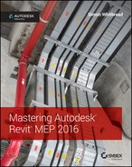
An example of this is an installation that has diffusers hosted in the ceiling as well as areas where the architect's design is for suspended fittings (see Figure 10.1). In this project, assume that there is an external architect and that the architectural model is being linked. This means that you cannot use ceiling-hosted air terminals. Although you can see the linked ceiling, Revit recognizes it only as a face. Because of this, the air terminals need to be created as either face-hosted families or families that are hosted to the level—that is, no physical hosting. Additionally, since Revit MEP 2014, there has been the ability to host an air terminal to a duct, regardless of how that particular family has been created. When placing a duct-hosted air terminal, click the Air Terminal On Duct button to access this feature.
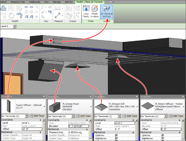
Figure 10.1 Diffuser hosting methods
The most important point here is that, after you commit to one type of family (hosted, level hosted, wall, and so on), you can exchange, for example, a ceiling-hosted air terminal only with a similarly hosted air terminal, not just those that are of the same category (see Figure 10.2).
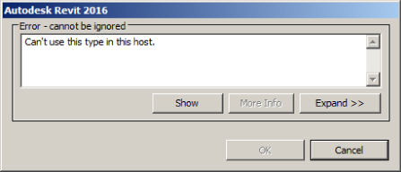
Figure 10.2 Hosting error message
The next problem is that the air terminals that are suspended are in fact the same type as those that are mounted within the ceiling tiles. The engineer wants to be able to schedule and filter them as one. How do you manage this?
The ability to copy/monitor air terminals (as well as lighting fixtures, mechanical equipment, and plumbing fixtures) means that the services engineers can monitor the locations of air terminals that the architect has placed because the architect is responsible for placing these objects. As with the other items that can be copied/monitored, the services designer can choose to copy the original family type from the linked file or “map” it to one of their own choosing. In Figure 10.3, you can see, however, that after the air terminals have been copied/monitored, regardless of the type of host association this ceiling-hosted family has no host but is in the correct location specified by the architect.
Figure 10.3 Copy/monitor level-hosting air terminals
Mechanical Equipment Components
Mechanical equipment comprises the components that make up the majority of large- to medium-size plant objects for the mechanical designer. From air conditioners (ACs) and air-handling units (AHUs) to air curtains and heat pumps, these all provide the geometry and parameters associated with HVAC design. As with all components, choosing the hosting type is important. A level-hosted object cannot be exchanged for a face-hosted or ceiling-hosted one.
Air-Conditioning/Handling Units
The heart of the mechanical air system, the air-conditioning or air-handling units, can start life as generic “boxes” with intake and exhaust. Although basic in construction and with no manufacturer data attached, generic ACs/AHUs can have the same number of parameters as more detailed families. Similar in dimension and performance to generic ACs/AHUs, the concept box can be swapped out during the detail design period for a more detailed manufacturer or construction-issue family, or even for a set of families if the AC/AHU unit has been constructed from its manufacturer's component parts (see Figure 10.4). It is, however, entirely likely that the connectors in this generic unit will not be in the correct location when the more detailed manufacturer's family is loaded. This can mean some rework is necessary in order to produce a more accurate model.
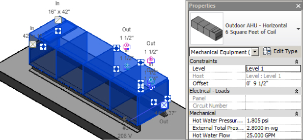
Figure 10.4 Basic AHU and parameters
The majority of large ACs/AHUs are generally placed on the level where they are inserted, while fan coil units (FCUs) or heat pumps are generally placed in a ceiling void, although they can also be in a plant room. The placement of these units can depend on whether the unit is mounted on rails, a plinth, or anti-vibration mounts and whether these mounting devices are part of the AC/AHU family (see Figure 10.5).
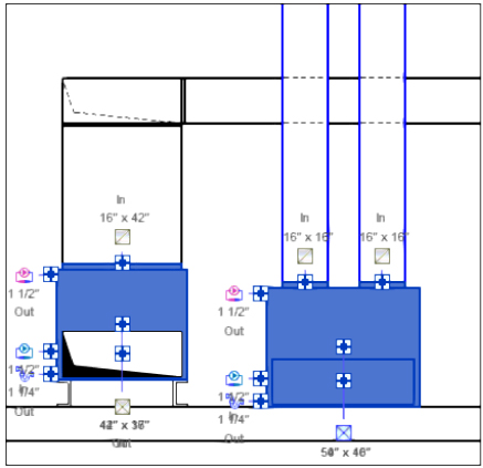
Figure 10.5 Floor-mounted and skid-mounted AC/AHU
VAV Boxes
Generally created as level-hosted families, variable air volume (VAV) terminal boxes are usually mounted somewhere within the ceiling void, suspended from the underside of the slab above. In terms of placement, these are given an offset relative to the building level associated with the active view. Using the Properties palette, the offset can be predefined prior to the VAV being placed in this case. This makes for an easier workflow than in previous releases, in which most objects were placed on the reference level and then subsequently moved to the correct elevation (see Figure 10.6).
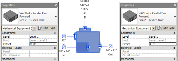
Figure 10.6 Changing the invert level
Connections to both AC units and VAV boxes can include heated- and chilled-water services and electrical for connecting to water and electrical systems (see Figure 10.7). Also note the connector labels in this view, which allow easier identification of connections and their flow direction, where applicable. These symbols also double as a shortcut to start creating ducts from the connector; just click the icon to start.
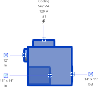
Figure 10.7 Typical mechanical and electrical connections to mechanical equipment
Heating and Cooling Elements
Heating coils, chilled-water coils, or reheat coils can be shown as part of the equipment or provided separately. They can also be duct mounted. Generally for FCUs, heat pumps, and most ACs/AHUs, the coil connections would be built into the equipment, but for a built-up AHU or for a VAV that may or may not include reheat, providing a coil separately can make it easier to swap out without changing the entire family. Duct-mounted coils need to be made adjustable to duct size and coil width (determined by the number of rows) and will need to have the pressure drop provided from the manufacturer's data.
Electric duct heaters can also be required. With these you need to ensure that you allow for the fire rating required. Building this into the family ensures that you are not relying on the users to remember it every time.
Ductwork
Ducts can be displayed in a variety of ways; they can be rectangular, round, oval, a placeholder, or, new to Revit 2016, fabrication parts, as shown in Figure 10.8 (refer to Chapter 24, “Fabrication Parts,” to learn more).
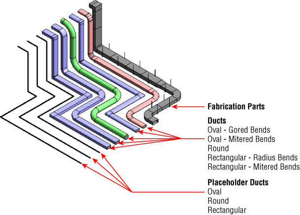
Figure 10.8 Ductwork
Placeholder ducts, as you can see in Figure 10.8, are shown only as a single line, although they retain nearly all the characteristics and properties of a regular duct. In Figure 10.9, you can see the differences. Placeholder ducts do not have values for Justification, Insulation, or Lining, because they are not needed at the conceptual stage of the project when placeholders are being used.
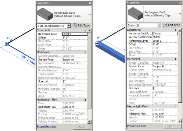
Figure 10.9 Design criteria for placeholder ducts
Within Revit, ducts are system families, and they provide the physical connections that hold systems together. This contrasts to the logical (conceptual relational) connections discussed in an earlier chapter. Ducts combined with fittings permit you to create a duct type, as described in the next section. Although ducts hold a huge amount of information, for the user there are several important considerations to note, such as the type of bends, transitions, and other fittings that make up the duct run. Also take into consideration lining and insulation, which can be applied to runs or parts of runs after placement.
Since Revit MEP 2014, we have had the ability to specify the type of system that a duct is associated with (exhaust, return, or supply), without it actually being connected to any equipment. You will be able to change the system type of a duct, even after it is connected to equipment, but not the classification. For example, if your duct is connected to a supply terminal, then you can change your system type to Outside Air, but not to return or exhaust air, as the Outside Air system type should have been created from the Supply Air system classification. If your duct is not connected to any equipment, you can change it to any system you like, as shown in Figure 10.10.
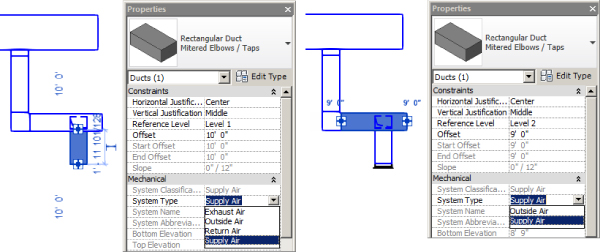
Figure 10.10 Ducts associated with systems
When highlighted in the System Browser, both ducts and placeholder ducts are highlighted in the drawing area. If a duct is created in the wrong system type, simply select one section of the run and change it to the required system. All the connected ducts and fittings will also change. This ability can have several benefits, including these:
- The user doesn't have to remember to select the appropriate system before creating a duct—its system type can be changed at any time.
- Differing systems can be connected together. An example of this for ducts could be a supply AHU with a redundant backup. Although the backup system is not included in the system calculations, it can connect to the main supply without affecting the calculations in that system.
In Revit MEP 2016, all systems (with the exception of fabrication parts) are named. Even though they may be default names, it is easy to change them on the fly. You also have the ability to divide a system. This is dependent on elements within the system not being physically connected and could be used as a means for breaking up large systems that may be slowing down the design process. To achieve this, select an appropriate system, as shown in Figure 10.11. Notice that although it is physically not connected with a duct, it is a single system. Also, with the supply air system selected, you can see the new Divide System button on the ribbon.
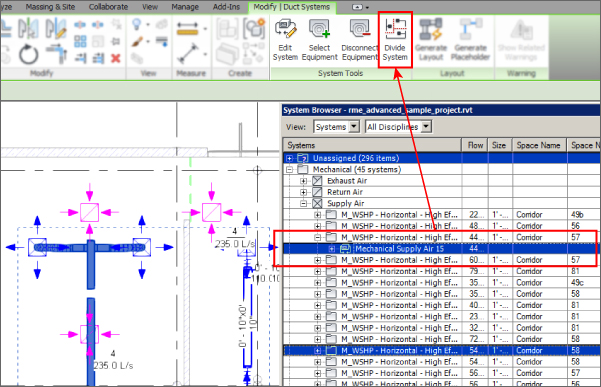
Figure 10.11 System Browser
Once you click the Divide System button, a message similar to the one in Figure 10.12 appears. The number of systems depends on the number of physical breaks in your original system.
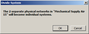
Figure 10.12 Divide System message
With the system now split, the original system and the new one (or however many have been created) are automatically sequentially numbered, as shown in Figure 10.13.
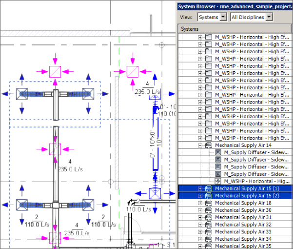
Figure 10.13 Systems shown separately
Interference checking in Revit is a comprehensive and accurate tool. Not only can you use the placeholder ducts (and pipes) in the interference check, but duct insulation can also be included as part of the process (see Figure 10.14).
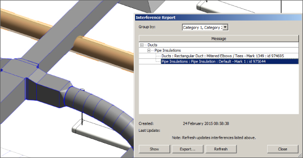
Figure 10.14 Interference check
Duct Types and Routing
Creating new duct types is a way of managing how your runs of ductwork connect into each other, such as whether or not bends are mitered. Although you can change fittings inserted retrospectively, it is much easier to create a run in one go, using either the automatic or manual tools, and duct types make that easier.
Creating New Duct Types
Although it may be tempting to create types with names such as Exhaust and Supply, try to keep these names more specific, such as Stainless-2D Radius/Taps or Galvanized-Mitered/Tees. This way, the user only has to think about what material was used for the duct. Using a name that specifies Supply or Extract may be initially attractive, but doing so can lead to ambiguity and misunderstandings among the modeler, designer, engineer, and potentially the client. Another downside to this is the need to create multiple types of bends, tees, crosses, and so on for all the different material types and system types you are likely to use.
To create a new duct type, or to edit an existing type, right-click one of the existing types in the Project Browser (as is typical for all Revit system families) and click Duplicate. This copies the existing duct type and appends the number 2 to the end of the name (for example, Mitered Elbows/Tees 2). Now right-click again and choose Properties, which opens the Type Properties dialog box. At this point, you can choose to rename the duct type and assign the necessary fittings. These fittings need to be preloaded to use them, but you can also reuse those already in use in the project/template.
Using Automatic Duct Routing
When using the automatic routing tools, as a rule of thumb you should work on small sections—all the feeds to a VAV box is one good example. This means the computer has fewer objects to calculate and the routing suggestions have less room for error. Before even starting this process, check the options under Mechanical Settings (see Figure 10.15) for default Duct Type, Offset, and Maximum Flex Duct Length values because these are used during the routing process. Also note that these settings can be set for the different system types.
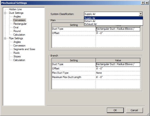
Figure 10.15 Mechanical settings
Now you're ready to use automatic duct routing. Here's how:
- Place your VAV box, ensuring that it is located at the correct height. You can change it later if needed, but this may lead to you changing your duct route. Sometimes it is worthwhile to place the unit at the correct level and create a short run of duct from each connector. This gives you the correct levels of ducts (and pipes) from which you can then adjust the default height (Offset), as described in step 8.
- Place your air terminals. At this point, it is a good idea to consider the following, not from a design point of view but from a Revit one:
- What type are the ceilings (if any)?
- If there are ceilings, should you use face-, ceiling-, or level-hosted families?
- Are you going to create your own placeholder ceiling to host your families?
- Should you use the ability to copy/monitor the air terminals already placed by the architect?
- Choose the type of air terminal. Is it top, side, or even sidewall entry?
- Once you've taken these things into consideration, it's time to start laying out the equipment. Figure 10.16 shows (1) a space where the upper limit has been defined as the level above; (2) the Specified Supply Airflow value for the space has been entered manually; (3) Calculated Supply Airflow has been computed using the analysis tools; and (4) Actual Supply Airflow is calculated from the flow rates for the air terminals that Revit finds within the space's boundaries.
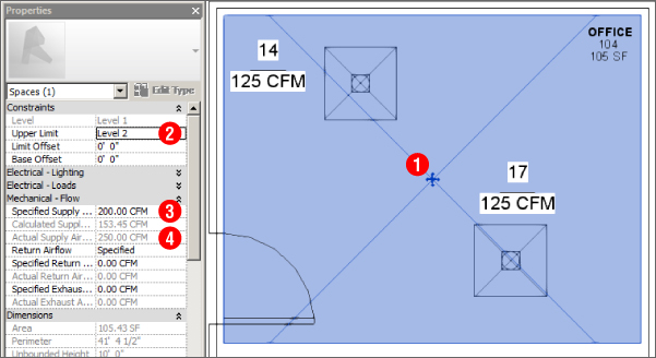
Figure 10.16 Space properties
- Creating a system is a relatively easy process in Revit MEP. Either you can select one air terminal, create the system, and then add others, or you can select all the air terminals you want to be in the system. On the ribbon, select the Duct option on the Create Systems panel (see Figure 10.17).
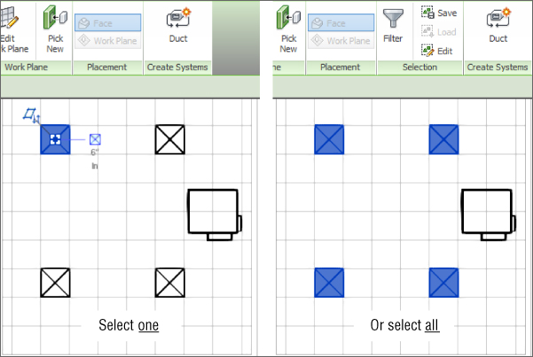
Figure 10.17 Create Systems panel
After you click the Duct button, the Create Duct System dialog box appears (Figure 10.18).
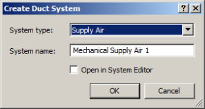
Figure 10.18 Create Duct System dialog box
This dialog box allows you to edit the system name and, if necessary, open the new system in the System Editor to add/remove objects and select equipment. Objects that are not part of the current system appear as halftone in the drawing area. When they are selected to be added to the system, their appearance changes to full weight (see Figure 10.19).
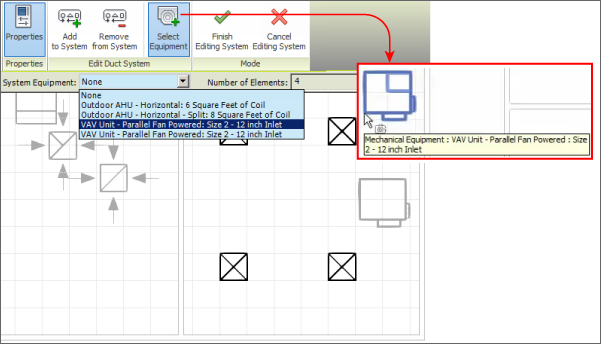
Figure 10.19 Add To System command
- Once you have completed adding air terminals, click Select Equipment, and either select the equipment from the Options Bar drop-down or select the actual VAV box indicated on the plan, as in Figure 10.19.
- Complete this task by clicking Finish Editing System. You have now created a logical connection/relationship between the parts, and now it is possible to start creating the physical connections. This is where the fun begins!
- Hover over one of the items in the system (but do not select it) and press the Tab key. All the items in the system—air terminals and the VAV box—will now be enclosed in a dotted-line box. Without moving your cursor, left-click. This selects the system, as shown in Figure 10.20, and displays the system in the System Browser. (Remember the shortcut if the System Browser is not displaying? Press F9).
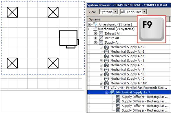
Figure 10.20 Tab-selecting the system
With the system selected, you have several options; one of these is to create a layout. You can use either regular ducts or the placeholder option.
- Select Generate Placeholder and, as shown in Figure 10.21, the sketch options for layout are displayed. For Solution Type, select Network, option 5. Remember that you can also edit the default settings for the duct offsets, as shown earlier in Figure 10.15, by clicking the Settings button on the Options Bar. Most errors that occur using Layout are associated with either settings that fail to deal with elevations and fittings assigned to duct types well, or duct or equipment that have not been placed at the correct elevations to allow the duct run to work at all.
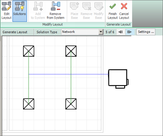
Figure 10.21 Generating a layout
You have several options for automatically generating your duct layout. These include Network, Perimeter, and Intersection options. Each can give you several solutions that can vary depending on the predefined settings for the duct layout, which can also be accessed from the Options Bar. Figure 10.22 shows that you can click the Edit Layout button, which allows you to select the layout lines in order to make changes to the layout. As a visual aid, main duct runs are shown in blue, whereas branch runs are shown in green. Using a plan and a 3D view side by side is a great way to ensure that a layout will work before clicking Finish Layout.
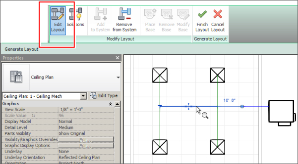
Figure 10.22 Ductwork routing solutions
- Once you have settled on your preferred layout, click Finish Layout, and the duct layout is created (see Figure 10.23). Notice that the placeholder ducts are shown only as a single line.
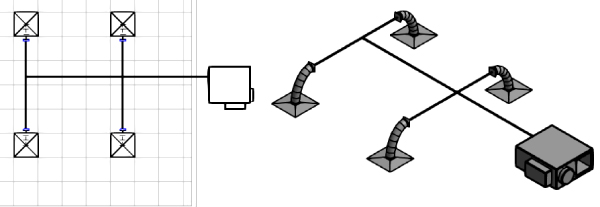
Figure 10.23 Completed duct layout
It's worth pointing out here that the sizes used for this layout are based on the connection sizes and the settings for duct sizes located in the Mechanical Settings dialog box. There is another important consideration at this point. The designer/drafter must ensure that the default settings for the main and branch ducts are high enough above the air terminals and associated equipment to generate the layout; otherwise, the Layout tool cannot generate a layout, even if the layout is created with placeholder ducts. This can be achieved in two ways: either by selecting the Settings button on the Options Bar (shown earlier in Figure 10.21) or by selecting the actual sketch lines of the solution, which allows the user to manually choose the offset.
Using Manual Duct Routing
Using the automatic tools may seem too limiting or even pointless to an experienced design drafter who already knows the sizes and routing that must be used. These tools are great for a quick mock-up or presentation of a design that is more conceptual. However, with experience, most users eventually settle for a variety, sometimes for no better reason than “a change is as good as a rest.” Occasionally, however, the manual tool is much more efficient, especially when connecting different areas into a system or laying out runs back to a rooftop AHU.
To begin manual duct routing, do the following:
- Click the Duct tool on the Home tab on the ribbon, and then choose the type and its various options from the Properties palette, as shown in Figure 10.24.
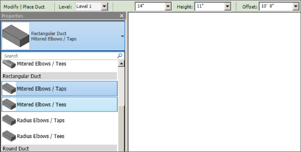
Figure 10.24 Duct types
Note the default settings in the Properties palette for constraints, including Justification, Reference Level, and Offset. The system type is undefined, and because the duct is unconnected, the airflow is 0.
You can adjust additional properties from the Options Bar and the Modify | Place Duct tab, shown in Figure 10.25.
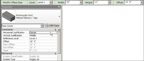
Figure 10.25 Duct settings
You can also inherit the elevation and size of existing connectors, whether from ducts or families, when connecting to them. For round or oval ducts, you can also choose the Ignore Slope To Connect option, meaning that the duct will connect regardless of slope or elevation differences between the connection points, or you can use the specified angle. These options are available from the Placement Tools panel of the Modify | Place Duct section of the ribbon as shown in Figure 10.26.
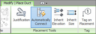
Figure 10.26 Duct placement tools
- The duct can then be created/drawn to whatever path you choose. For vertical offsets, type the new height into the offset box on the Options Bar. For an angled setup or set-down, it is best to work in an elevation or sectional view.
In Figure 10.27, the duct has been split and a section created. To create a duct set-down, you would hover over one end of the duct, right-click the connector, and select Draw Duct. The duct would then be drawn along the preferred route.
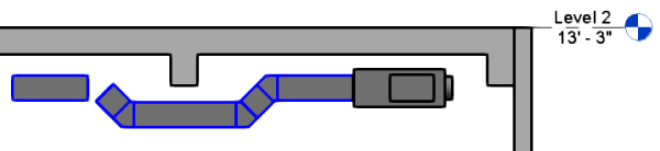
Figure 10.27 Editing duct in sections
- Using tools such as the Trim command, you can complete the run, as shown in Figure 10.28. Bear in mind that sketching a duct in sections or elevations must be done from connector to connector. Otherwise, the work plane of the view will be where the duct is placed. In section and elevation views, this is where the view's cut plane is. You will see some strange duct runs if you don't pay attention to that.
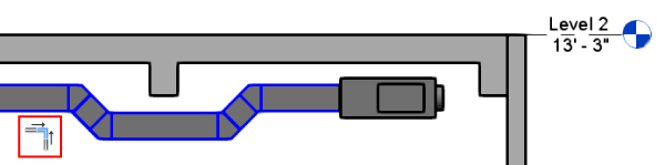
Figure 10.28 Completing the set-down
When creating ducts that set down/up or drop/rise, it can be much easier to model these in a section or elevation view, as shown in Figure 10.27 and Figure 10.28. To do this, first you need to create a suitable view. Quite often, individuals have a personal section that they move around the model. It can be opened when required, and then the duct (or whatever service is being worked on) is modified and the view is closed. This section, which should be named for the individual, can then be used to show a quick 3D view of the area using the Orient To View option.
Adjusting Fittings and Extending the Design
Changing the justification of ducts is a relatively easy task, but it can take practice to actually master. Selecting a duct or a run of ducts/fittings gives the user the option to change justification. Select your duct run, and from the Modify tab, select Justify.
This opens the Justification Editor, shown in Figure 10.29. Here, the control point can be displayed, and the alignment along the selected route can be selected by using the Alignment Line button. You can choose justification by using one of the nine Justification control buttons. This can have significant effects on your layout, so it is best to use this tool in small, easy-to-view sections or 3D views.
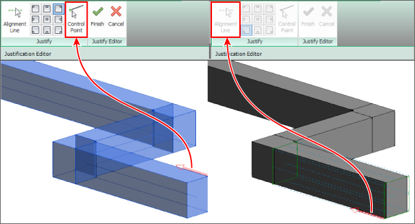
Figure 10.29 Duct Justification Editor
You can also change an entire duct run from one type of duct to another. All you need to do is select the duct run. The only proviso is that flexible ducts, air terminals, and mechanical equipment are not in the selection set, so you must either Tab-select the run or use a selection window, and then apply a selection filter, as shown in Figure 10.30.
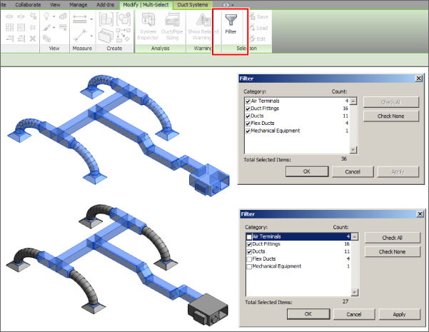
Figure 10.30 Applying a selection filter
This is a logical step, because the ducts and duct fittings in the selection set are usually also defined within the duct type. Therefore, when you select the objects and click the Change Type button, you are presented with a condensed Properties box that allows you to change the run type for others already in use in the project (see Figure 10.31).
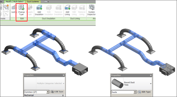
Figure 10.31 Changing the duct type
In the next example, the design has gone through a few iterations, and changes have been made to various fittings and portions of the duct run. This is where the Reapply Type option can help to clean up small discrepancies in your design. This tool is also a great help if you make changes to Routing Preferences in the duct type and/or Angle properties in Mechanical Settings. You can update existing runs: select the entire run—just as you did earlier in our previous example. This allows the user to reapply the original duct types to the objects selected, as shown in Figure 10.32.
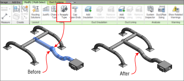
Figure 10.32 Reapply duct type
The direction of flow and graphical warnings are really helpful for the designer. The direction of flow is a temporary display when you select any object that has a mechanical or piping connection. This is a great benefit for designers and drafters because they can visualize which way air (or gas or water) is flowing through an object. As you can see in Figure 10.33, the selected VAV box has two supply ducts: one entering from the right and the other exiting from the left. There is also a return-air and electrical connection.
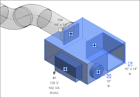
Figure 10.33 Flow connectors
Warnings related to MEP connections can be displayed as graphical notifications when there is a disconnect in the system. You can change the warnings to suit your current task from the Analyze tab. Click the Show Disconnects button and then select the options you require, as shown in Figure 10.34.
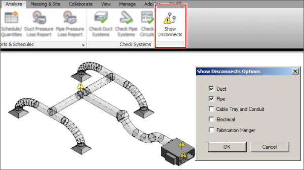
Figure 10.34 Show Disconnects options
With the disconnects visible, we can clearly see open ends to ducts or pipes, which will result in incorrect calculations since Revit is expecting a contained system. Here we can make use of the Cap Open Ends tool. Simply select a duct or selection set of ducts and click the Cap Open Ends button displayed on the ribbon, as shown in Figure 10.35.
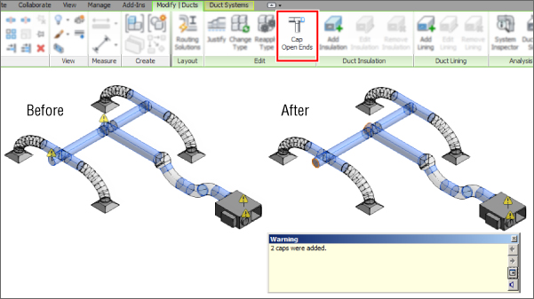
Figure 10.35 Cap Open Ends button
To extend an existing layout, as indicated in Figure 10.36, select one of the fittings (typically a bend or tee). Notice a small plus sign (+) adjacent to the side of the fitting that does not have a connector. Clicking this turns a bend into a tee and a tee into a cross, eliminating the need to delete a fitting and insert an appropriate one.
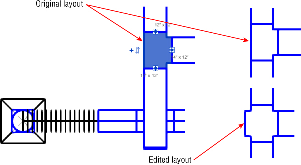
Figure 10.36 Extending the design
Duct Sizing
The most important factor in duct sizing is that the components in the system are connected together properly so that data can pass between components via duct and fittings. Also, the system must have a valid airflow, so either you specify the airflow of the air terminals or that flow is specified from the space and volume calculations. And, although not crucial, you consider the name of the system. Don't use the default; instead, make it something meaningful to your project or company. This last suggestion will not stop the tool from working, but it makes reporting much easier to read.
Use the Tab key to select your system so that all the sections of duct and duct fittings in the system are highlighted (Figure 10.37).
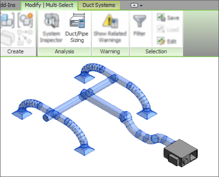
Figure 10.37 Tab-selecting the system
The Duct/Pipe Sizing tool is located on the Modify | Multi-Select tab of the ribbon. This button becomes active when you select a single duct or duct run that is part of a fully enclosed system, whose components are connected correctly in regard to flow direction. Clicking the button opens the Duct Sizing dialog box. Figure 10.38 shows its available options.
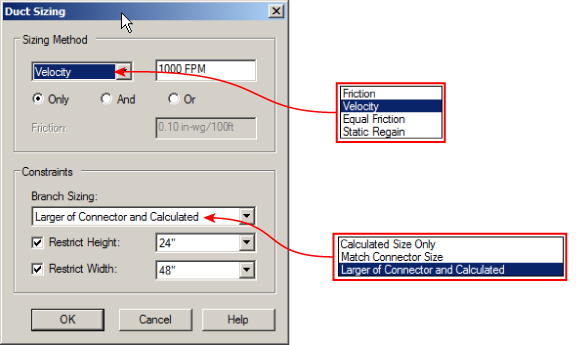
Figure 10.38 Duct Sizing dialog box
Choosing a Duct Sizing Method
Although the sizing method you choose can be applied to an entire system, this is not necessarily the most efficient way to do things. If there are 5,257 objects in your system, it's probably not a great idea to ask your computer to process that amount of information—it may take a while! The logical choice is to split the task of duct sizing into manageable sections, such as a floor plan, a zone, or a group of air terminals fed from the same VAV box.
The various methods for sizing are as follows:
- Friction
- Velocity
- Equal Friction
- Static Regain
Friction and Velocity can be used independently of each other when using the Only option. Alternatively, they can be used in conjunction with each other with the And and Or functions.
These options allow the designer to force the sizing ducts to meet the parameters specified for both Velocity and Friction. With the Or method, the least restrictive of either of the parameters is used. The Equal Friction and Static Regain methods use the ASHRAE duct fitting database.
You set air properties using the Mechanical Settings dialog box. The sizes of ducts used in the sizing calculations are available here as well (see Figure 10.39 and Figure 10.40).
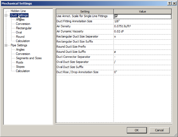
Figure 10.39 Clicking Duct Settings in the Mechanical Settings dialog box
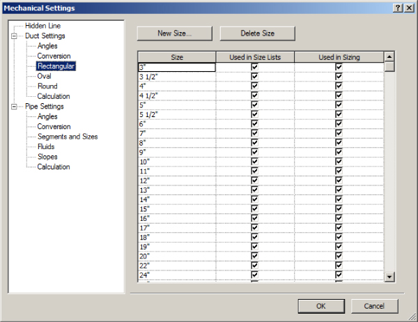
Figure 10.40 Viewing duct sizes in the Mechanical Settings dialog box
During the sizing process, you can also apply constraints to the branch parts of the run. These are defined as Calculated Size Only, Match Connector Size, and Larger Of Connector And Calculated (see the Constraints section in Figure 10.38). Depending on the stage of the design or your actual role (such as consultant), you could choose Calculated Size Only, because the design is still in its early stages and the equipment is generic. These settings allow you to coordinate with other model components in areas where space is limited. For example, if you have only 2′-0″ (600 mm) of space above the ceiling, you could restrict the height of your duct to 20″ (500 mm).
However, later in the project when the equipment has been specified, as a contractor you may want to select Match Connector Size and Larger Of Connector And Calculated to reduce the number of duct sizes used on the project, thereby reducing your manufacturing costs.
This dialog box also allows you to specify a limit on the size of the ducts, which can further reduce costs or give you the ability to specify, say, a continuous duct height in places where you know access is a potential issue.
To add insulation and lining to a selection set that contains both ducts and duct fittings, simply create your selection set and choose the appropriate option, as shown in Figure 10.41.
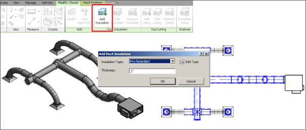
Figure 10.41 Insulation and Lining tools
Lining and insulation can have overrides or filters applied so that they display in the required manner, even to the extent of showing insulation as transparent with a hidden line style, also shown in Figure 10.41.
Although lining and insulation can be added only as instance parameters, the workflow for using this tool is relatively straightforward. Even so, if the entire system requires lined or insulated ducts, you have to select all ducts for the system and then specify the insulation or lining required.
Duct sizing works only where air terminals, ducts, duct fittings, and mechanical equipment are seamlessly connected with no gaps and where the equipment has a defined airflow. This airflow could be entered as part of the initial analysis or subsequent manipulation of the objects.
Once a system is created, you can use the analytical tools to inspect the duct system for airflow, pressure, and pressure loss. From the System Browser, select the system you want to analyze (as shown in Figure 10.42). Remember, you can also Tab-select the system. With the system selected, click System Inspector on the ribbon. If the Inspector tool isn't available, it's a clue that something is wrong.
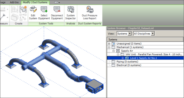
Figure 10.42 Selecting a system
The System Inspector tool, shown in Figure 10.43, activates the extended floating toolbar. Click Inspect and move your cursor over the elements in the system; notice that airflow and pressure loss are defined.
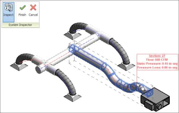
Figure 10.43 System Inspector
As with all calculations, you may want to keep a record of this analysis as part of your project documentation. From the Analyze tab, you can create duct (or pipe) pressure-loss reports, as discussed in Chapter 8, “HVAC Cooling and Heating Load Analysis.” From the Reports & Schedules panel, select the appropriate tool. You now have a choice: either select the system first or specify the system you want to create the report on in the Analyze tab. Once the system is selected, the dialog box shown in Figure 10.44 is displayed. In this dialog box, you can specify the fields to use and save the report format for later use. Clicking Generate creates an HTML web page of your results.
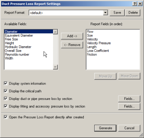
Figure 10.44 Duct Pressure Loss Report Settings dialog box
Using the Duct Routing Tools
Now that you have reviewed the process of using the duct routing tools, you will learn how to apply them in a simple exercise:
- Open the
Chapter10_Dataset.rvtfile found at this book's web page:www.sybex.com/go/masteringrevitmep2016. - Open the floor plan view 1 – Mech, as shown in Figure 10.45. You can see that there are four air terminals (level hosted) mounted at 8′-0″ (2400 mm) above level and a VAV unit mounted at 11′-0″ (3300 mm). These have already been connected to a supply air system.
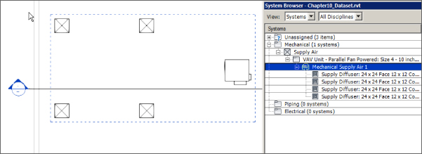
Figure 10.45 Plan view
- Hover your cursor over any one of the air terminals and press the Tab key. This highlights the system, as indicated in Figure 10.45. Left-click, and the Modify | Duct Systems tab is activated. Click the Generate Placeholder button.
- Click the Settings button on the Options Bar, and check that the Duct Conversion settings are as follows:
- Main duct: Rectangular Duct: Mitered Elbows/Tees
- Offset: 11′-0″ (3,300 mm)
- Branch duct: Rectangular Duct: Mitered Elbows/Tees
- Offset: 11′-0″ (3,300 mm)
- Flexible duct: Flex Duct Round: Flex – Round with a maximum length of 6′-0″ (1,800 mm)
- Use Solution Type: Network, 1 of 6, and click the Finish Layout button. Activate the default {3D} view and notice that, as shown in Figure 10.46, the main run of duct is shown as a single line. If the flexible duct is also shown as a single line, this is not by design; it indicates that the flexible duct is not connected correctly, which needs to be rectified. Depending on several factors, your results may be slightly different.
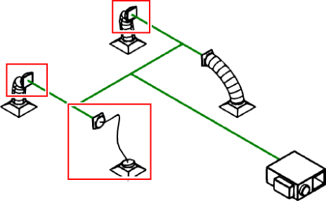
Figure 10.46 Default 3D view with flex errors
- If the flex duct is too short to be displayed properly, select one of the rectangular-to-round transitions and move it 2′-0″ (600 mm) toward the center of the duct run. This stretches both the placeholder duct and the flex duct, as shown in Figure 10.47. Repeat this process for each transition. You may find it easier to tile the open view windows and select the transition in the 3D view but then actually move it in the plan view. Clicking the plan view should retain the selection, but if you lose it, just right-click and choose Select Previous.
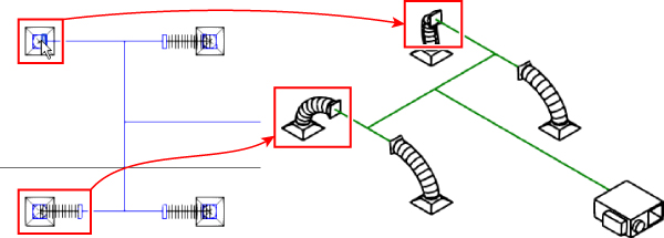
Figure 10.47 Moving transitions
- The placeholder duct is ideal for concept and preliminary design, in which little detail is required for your drawings. Once this stage has passed, you can change the placeholder ducts to actual ducts with fittings. To do this, simply select the placeholder ducts in the 3D view, by either selecting them individually or selecting everything and using the Filter tool, as described earlier in this chapter. Then click the Convert Placeholder button on the ribbon. Check to see that your results match Figure 10.48.
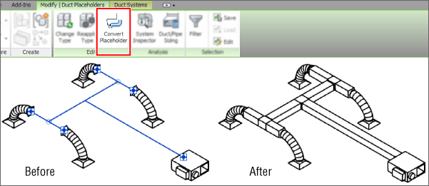
Figure 10.48 Converting duct placeholders
- With the duct in place, open the view Section 1. Here you can see there is a clash where you need to edit your duct to go under the beam. Using the Split tool, split the duct and delete the inner section and duct union fittings, as shown in Figure 10.49.
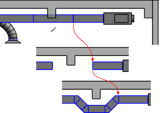
Figure 10.49 Split duct
- Complete the duct as required to avoid conflict with the beam.
The Bottom Line
- Distinguish between hosted and level-hosted components. Deciding whether hosted or level-hosted components are used is crucial for the success of your project. This decision will play a large factor in performance and coordination with other companies.
- Master It Should you choose hosted or level-hosted components for your project?
- Convert placeholder ducts into ducts with fittings. Using placeholders is a great way to “rough in” a duct layout without having to be too specific. Fittings are not used and the layout is extremely flexible.
- Master It When progressing your conceptual design, at what point should you convert placeholder ducts into ducts with fittings?
- Use the various duct routing options. When Revit MEP 2016 is used for duct layouts, the user must understand the functions of automatic duct routing and manual duct routing. Once these functions are mastered, the user can lay out any type of ductwork system.
- Master It When asked to submit a design proposal for a multifloor office building, the HVAC designer needs to show a typical open-plan office that includes the supply and extract ductwork. How should the designer start this process?
- Adjust duct fittings. Duct fittings are needed to connect duct runs together correctly and to produce documentation for construction. Being able to add or modify fittings can increase productivity.
- Master It You have just finished your modeled layout and given it to your employer for review. Your boss asks you to remove a couple of elbows and replace them with tees for future expansion. What method would you use to accomplish this quickly?