Chapter 23
Sheets
Construction documents, drawings, and specifications are likely to continue to be our instrument of service to our clients for many years to come. Autodesk® Revit® MEP 2016 uses sheets to allow us to organize our model views, schedules, legends, and details into documents suitable for printing whether using paper or electronic formats like PDF.
Sheets can be compared with creating a layout in AutoCAD, assuming you have prior experience with that task. The significant difference is that sheets use the plan, section, and elevation drawings that are derived from the views of your model. These are far better coordinated because all of them are located in this project, and they are integrated more fully and reliably.
As you've learned, changes to the model are propagated throughout the project, so any sheets containing a view of the changed area are automatically updated. Sheets also carry revision and document issuance information. As you make changes to your design and add revision clouds, your sheets can show the latest revision number and date. Don't think of your sheets as separate from your project; they are integral to the process.
We can imagine a future where clients and contractors will require virtual models that are our official deliverable. Until that time we can rely on sheets to help us prepare and present our work. Creating and printing sheets is easy, consistent, and reliable.
In this chapter, you will learn to do the following:
- Create a titleblock
- Establish sheets in your project
- Place views on sheets
- Print and export sheets
Creating a Titleblock
Whether you refer to it as a sheet border, drawing border, or some other name, a titleblock consists of the graphics that define the boundaries of a sheet. Some of your clients may have specific requirements for the size, shape, and information provided in the titleblock used for their projects. You may have already developed these for use in CAD projects as well as a company titleblock for use when the client does not specify one. These existing CAD titleblocks can be used to develop titleblock families for your Revit projects. This ensures a consistent look between your Revit sheets and CAD sheets, especially if the need should arise to combine CAD and Revit drawings in a document set.
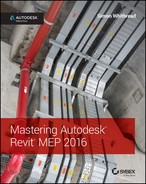
Titleblocks are a unique family type within Revit. To create a new titleblock, you can choose from one of the basic sizes available in your template library. When you choose to create a new family, you can browse to the location of your titleblock family templates. Depending on which templates you choose to install with Revit MEP, you will see templates available for standard sizes or one for creating your own unique size. Clicking New ⇨ Title Block on the Application menu takes you to the location of your titleblock templates, as shown in Figure 23.1.
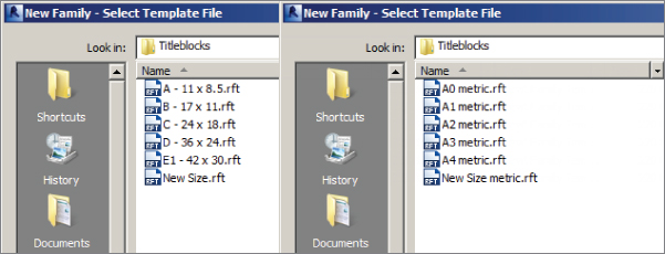
Figure 23.1 Titleblock templates
The templates for creating a titleblock contain a rectangle for defining the limits of the sheet size. If you are using the New Size template, the rectangle can be modified by dragging its lines to the appropriate size. You can also select one of the lines and edit its dimensions so that you can input the precise size for the limits of the titleblock. If you are using a template with a preset size, the rectangle is already dimensioned to the appropriate size.
Using Existing CAD Graphics
Once you have chosen a template and the size has been determined, you can import a CAD titleblock for reference. When working in the Family Editor, you cannot link a CAD file. The styles in the CAD file will become Revit styles within your titleblock family, so you may want to do the work in a file and then copy the Revit linework to another blank file when finished. This keeps your titleblock family free from unwanted styles. Chances are there will be many unnecessary styles from the CAD file and they do not conform to your naming standards. This excess information will be carried through to every project that uses the titleblock. The idea here is to create a titleblock family that is in clean, native Revit format.
Click the Import CAD button on the Insert tab of the Family Editor to import your CAD titleblock. You may want to use the Preserve option for the colors in the CAD file so that you can draw an appropriate Revit line to match the line weight based on the CAD color. Align the imported CAD file with the rectangle in the family so the titleblock fits properly, and pin it in place to avoid any accidental movement.
The Line button on the Create tab of the Family Editor allows you to draw the lines necessary to trace the imported CAD graphics. You can use the Pick Lines tool on the Draw panel of the Modify | Place Lines contextual tab to generate Revit lines quickly in the same location as the CAD graphics.
Using Text and Labels
When you finish creating Revit lines that match those of your CAD titleblock, you also need the annotation objects that provide sheet and project information. Determine which annotation objects in the CAD file can be Revit text objects and which need to be labels. Any text that is constant from sheet to sheet and does not need to change during the course of a project can be a text object in your titleblock family. For example, if your titleblock provides information about who designed, drafted, and checked a drawing, you can place text in the titleblock as the titles for this information. Figure 23.2 shows imported CAD graphics in a titleblock family with a text object placed in the same location as text in the CAD file.
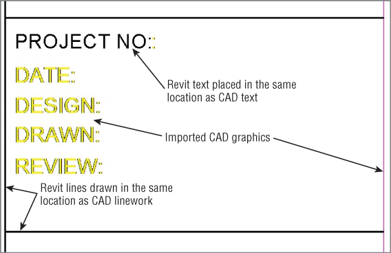
Figure 23.2 Revit text object used in a titleblock family
For more information about using the drafting tools available in Revit 2016 and using CAD graphics, see Chapter 22, “Details.”
You can create text styles within the titleblock family to match those used in the CAD version of the titleblock. You create different styles by duplicating the standard text style available when the family is created.
A titleblock typically contains information about the project in general along with information specific to the items shown on the sheet. The key to coordinating the information that appears on your sheets is to coordinate from where the information is taken.
The most effective way to provide information on a titleblock is by using parameters. The use of parameters lets you make changes in a single location that updates all of your sheets in the project. Labels are used to show the information in a titleblock. Label styles should be created to match the text used in your CAD titleblock.
Labels should be used in your titleblocks in the same way that attributes are used in CAD. Click the Label button on the Create tab to create a label. You can edit the default label style by clicking the Edit Type button in the Properties palette and then the Duplicate button in the Type Properties dialog box.
When you click in the view to place the label, the Edit Label dialog box appears with a list of available parameters for the label. These are all built-in parameters that exist for either sheets or project information. If one of the parameters matches the kind of information you are trying to include in your titleblock, select it from the list and click the green arrow button to add it to the label, as shown in Figure 23.3. These parameters are available in the properties of your project's sheet views or in the project information on the Manage tab. As you provide them with values or edit them, the label in the titleblock family updates.
Figure 23.3 Adding a parameter to a label
When you click OK to close the Edit Label dialog box, the parameter's Sample Value becomes visible in the view. You'll need to move it to a better location, and you can edit the label in the view in the same way as you would a text object. Clicking the label activates grips for editing the location, rotation, and limits of the label.
If your titleblock requires a label that is not one of the built-in parameters in the list in the Edit Label dialog box, you can click the Add Parameter icon in the lower-left corner of the dialog box. In titleblock families, only shared parameters can be used for custom labels. Click the Select button in the Parameter Properties dialog box to choose a parameter from your shared parameters file. If the parameter does not exist in your file, you can create one. Figure 23.4 shows an example of shared parameters used in titleblock families. See Chapter 6, “Parameters,” for more information on creating and using shared parameters.
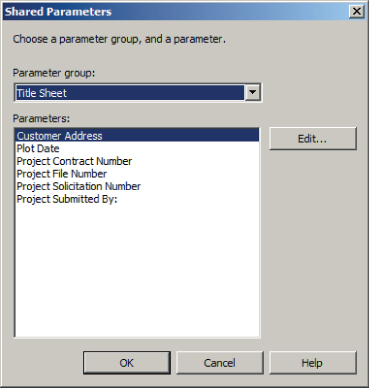
Figure 23.4 Shared parameters sample for a titleblock
If your titleblock contains an area for a sheet revision schedule, you can create a schedule within the titleblock family that uses the parameters for revisions. On the Family Editor's View tab, you click the Revision Schedule button on the Create panel.
The Revision Properties dialog box looks the same as a regular schedule properties dialog box, with parameters for revisions. The schedule will automatically be populated with parameters, but you can use whichever parameters you choose. You cannot create additional parameters for a revision schedule. Figure 23.5 shows the default settings for a revision schedule.
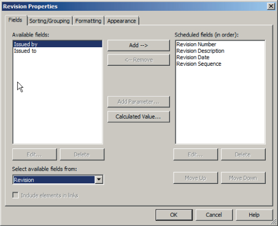
Figure 23.5 Revision schedule properties
On the Appearance tab of the Revision Properties dialog box, you can choose whether the schedule is built from the top down or the bottom up. You can also set the schedule height to a specific value to keep it from growing outside the bounds defined by the titleblock, or you can allow it to have a variable height.
Once you have set the schedule properties, you can insert the schedule into the titleblock graphics by dragging and dropping it from the Project Browser. After placing the schedule in the view, you can select it and choose a rotation option from the Rotation On Sheet drop-down list on the Options Bar. This allows you to orient your revision schedule vertically if necessary.
Take some time to explore the titleblock families that are provided with the software to see how the revision schedule is configured.
Using Logos and Images
If your titleblock contains a company logo, you can include it in your Revit titleblock family as either an image or linework. Linework used to represent a logo can be made into an annotation family that can be loaded into the titleblock family. This reduces the number of lines in the titleblock family, because many logos tend to contain numerous small lines. This also allows you to make changes to the logo without having to edit the titleblock family, except to reload the logo.
If you have an image file for your logo, you can load it into the titleblock family by clicking the Image button on the Insert tab in the Family Editor. You can resize the image to fit the titleblock graphics as necessary. Test the quality of the logo image by printing a sample sheet to ensure that the image used provides the expected results.
It may be best to have whoever is responsible for generating your company logo create one specifically for your Revit titleblocks. The image file should be a high-quality image at a reasonable resolution, yet a small file size. The resolution should be adequate so that at full size, it needs no, or little, resizing within the titleblock family. That can negatively affect its appearance.
Working with Sheets in a Project
Creating sheets in your Revit projects is a simple process of right-clicking the Sheets heading in the Project Browser and selecting the New Sheet option. You can also use the Sheet button on the Sheet Composition panel of the View tab. The New Sheet dialog box, shown in Figure 23.6, lists any titleblock families that are loaded into your project. You can select which titleblock to use for the sheet and click the OK button. If your titleblock has not been loaded into your project, you can click the Load button to browse for the appropriate titleblock.
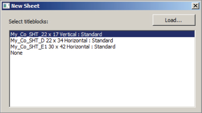
Figure 23.6 Titleblock families in the New Sheet dialog box
The bottom half of the dialog box, which is not shown in Figure 23.6, allows you to select any placeholder sheets that you may have created. Creating placeholder sheets is discussed later in this chapter.
Once you have chosen a titleblock and clicked OK, the sheet will be created and active in the drawing area. Depending on the parameters you have in your titleblock family and the data you may have already entered into the project, some of the information may already be filled out in the sheet. Revit automatically applies a sheet number to the sheet, starting with A101. When you change the sheet number, the next number in the sequence will be applied to the next sheet. For example, if you give a sheet a number of M-1, the next sheet you create will automatically be numbered M-2.
You can change the values of the labels in the titleblock either by selecting the titleblock and editing them in the drawing area or by selecting the titleblock and changing the parameter values in the Properties palette. As with all parameters, if the label turns red when selected, that means it is a type parameter and must be edited in the type properties of the selected object. Some of the labels may be properties of the project information and may not appear in the properties of the sheet. Edits to Project Information parameters are applied to all sheets where labels are reporting the information. You can access the Project Information parameters by clicking the Project Information button on the Manage tab.
As you give your sheets names and numbers, they begin to appear in the Project Browser based on your sheet organization settings.
Organizing Project Browser Sheets
You can organize the sheets that you create in your projects in the Project Browser for easy access and coordination. Right-click the Sheets heading in the Project Browser, and select Browser Organization to establish the organizational structure for sheets in your project. The Browser Organization dialog box appears and displays the Sheets tab, as shown in Figure 23.7. A few preset options can be used, or you can create new types for custom organization.
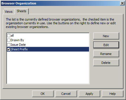
Figure 23.7 Preset types for browser organization of sheets
To create a new type of organization, click the New button on the right side of the dialog box. Give the organization type a name that describes how the sheets will be organized. This opens the Browser Organization Properties dialog box, similar to the one that appears for organizing views. The first tab allows you to apply a filter rule to the sheet organization. You can filter by parameters that apply to sheets. On the Grouping And Sorting tab, your sheets can be grouped by parameters that apply to sheets, as shown in the example in Figure 23.8. You can apply up to six levels of grouping to organize your sheets.
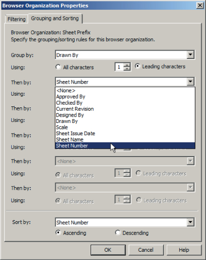
Figure 23.8 Parameters available for sheet organization
Once you have chosen a parameter for grouping, you can specify the use of all the characters or a specific number for display in the Project Browser. Figure 23.9 shows how sheets appear in the Project Browser based on the settings for organizing by sheet number using one leading character. The sheet groups are listed alphabetically by default.
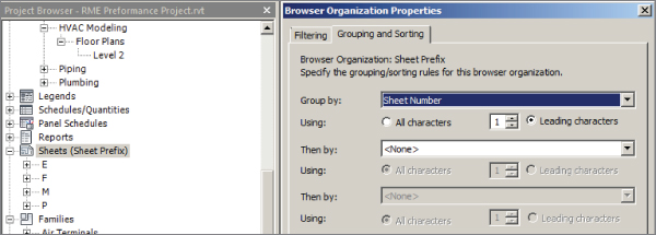
Figure 23.9 Sample sheet organization by sheet number
You can add other parameters to sheets so that they can be listed in the Project Browser as desired. Figure 23.10 shows that a project parameter called Sheet Discipline has been created to organize the order of sheets in the Project Browser.
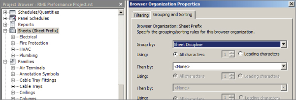
Figure 23.10 Custom parameter used for sheet organization
Additional levels of grouping are useful when you have a large number of sheets. Figure 23.11 shows a parameter called Sub-Discipline being used as a secondary level of organization. This makes it easier to find specific sheets after the sheet list becomes very large. Only one of the subdisciplines has been expanded in the Project Browser for image clarity.
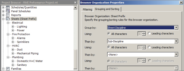
Figure 23.11 Parameter used for two levels of sheet organization
You can search the list of sheets for specific words by right-clicking the Sheets heading in the Project Browser and choosing the Search option. This feature can be useful for locating specific sheets or sheet types in a large project. The search results will even be applied to the names of views that are located on sheets.
Placing Views on Sheets
You can place views onto sheets by simply dragging them from the Project Browser onto a sheet that is open in the drawing area and clicking to place them. You can even drag and drop a view onto a sheet name in the Project Browser. This opens the sheet for placement of the view.
A guide grid, which is a set of lines (or graph paper) that appear overlaid on a sheet, can be used for placing a view in a specific location on a sheet. Whether or not a sheet contains a guide grid is determined by the sheet properties. You can choose the grid style by using the Guide Grid parameter of the sheet properties, as shown in Figure 23.12.
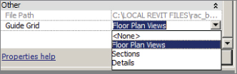
Figure 23.12 Guide Grid parameter
To create a guide grid, you must have a sheet open in the drawing area. When you click the Guide Grid button on the Sheet Composition panel of the View tab, you are prompted to give the grid style a name. Consider using names based on the types of views placed onto the sheets or based on a unique feature of the building, such as its shape, that determines what portion of the building is shown when dependent views are used.
A standard grid of blue lines appears over the sheet after you have given it a name. The size of the default grid is determined by the extents of your titleblock. You can select the grid by clicking one of the lines at the outer edge. This activates grips that allow you to size the grid manually, as shown in Figure 23.13. You can move the entire grid by selecting the grid, placing your cursor over an outer edge line, and dragging it. If you move a guide grid, its location changes on any of the sheets in which it is used. You can also use the Move tool for more accurate placement of the grid. You may want to consider pinning your guide grids in place once you have established their location and settings.
Figure 23.13 Grips for editing the size of a guide grid
When you select a guide grid, you can modify the spacing of the lines by accessing its properties. The Guide Spacing parameter, shown in Figure 23.14, allows you to set the size of the grid.
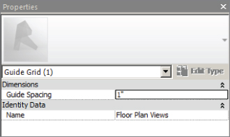
Figure 23.14 Guide Spacing parameter
You can move the grid lines when establishing the grid's location on the sheet by selecting the move command and snapping to the intersection of a grid, then moving that intersection to an appropriate point on the title sheet. However, there really should be no need to move the entire grid. Establish the spacing first, and if the grid must be moved, use the Move tool for accuracy. The key is that after you establish a grid style, it appears in the same location on each sheet to which you apply it. You can apply only one Guide Grid style to a sheet at a time.
When you drag a view from the Project Browser onto a sheet, you click to place it on the sheet. It does not snap to the guide grid at this time. You can then select the view and use the Move tool to align it to the grid by selecting a point on a datum object such as a column grid line, reference line, reference plane, or level and moving it to one of the guide grid lines. Though less useful, you can also snap to the viewport boundary. The view snaps to the guide grid line when a point on a datum object is selected.
Figure 23.15 shows how a view would be moved from a point on a column grid line in order to line up with a guide grid line.
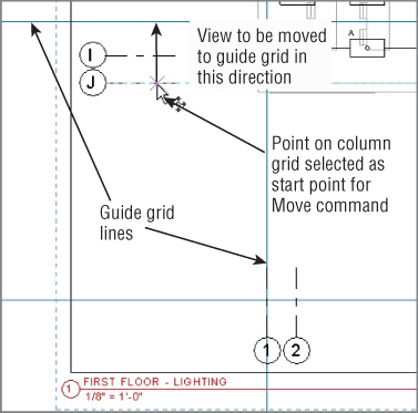
Figure 23.15 Moving a view to a guide grid line
Guide grid lines do not print when they are visible in a sheet. You can control their visibility either by using the parameter in the sheet properties or by turning off their category in the Visibility/Graphic Overrides settings for the sheet. The Guide Grids category is located on the Annotations tab of the Visibility/Graphic Overrides dialog box.
When you place a view onto a sheet, you have the option to rotate it by selecting a rotation direction from the drop-down that appears on the Options Bar during placement, as shown in Figure 23.16. For example, a portrait orientation on the sheet might work better for a tall building's elevation views. You can change the rotation of a view after the view has been placed by using the same drop-down.
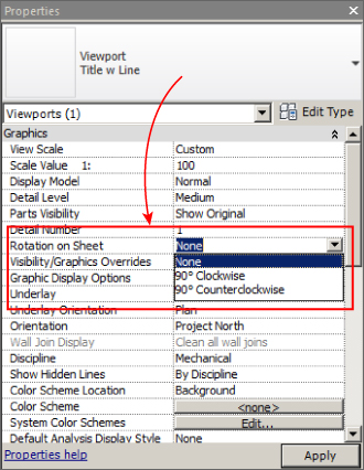
Figure 23.16 View rotation options
This does not allow you to continue rotating the view in the chosen direction. The settings on the drop-down are in relation to the normal orientation of the view. Thus, you can display the view normally, rotated 90 degrees clockwise, or rotated 90 degrees counterclockwise.
Working with Viewports
Rotating a view causes the view title to be rotated as well. The style of a view title is determined by the viewport type. Viewport types can be created so that the same kind of views can have different title styles. For example, an enlarged plan is a floor plan view, but you may want to use a callout bubble for the location of the view, whereas a normal floor plan does not require a callout bubble. Drafting views of details do not need a title if the detail title is included in the detail itself, so a viewport type without a title would be used.
When you select a viewport on a sheet, the properties that appear in the Properties palette are for the view. Clicking the Edit Type button displays the type properties for the viewport, shown in Figure 23.17.
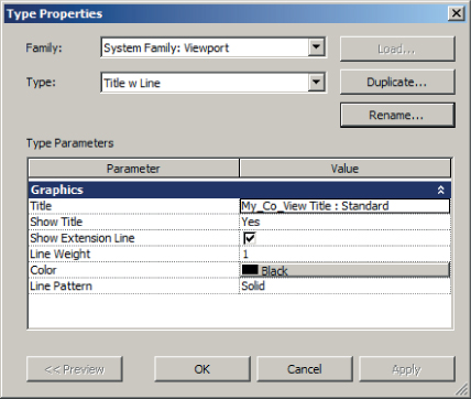
Figure 23.17 Type properties of a viewport
You use the Title parameter to define the annotation family used for the viewport title. Different view title families can be loaded into your projects for different viewport types. The Show Title parameter can be used to create a viewport type without a title for views that do not require one. In those cases, the sheet name is usually sufficient to describe what is visible on the sheet, so a view title is a bit redundant. Another choice is to show the title only when a sheet has multiple viewports.
To change the location of a viewport title on a sheet, you can click the title line and drag the title to the desired location. To change the length of the title line, you must select the viewport. This activates grips at the ends of the title line that can be dragged to change the line length.
By default, the title of a viewport is the same as the name of the view in the Project Browser. Project views have a parameter called Title On Sheet that enables you to use a title that is different from the view name. This helps you keep your views organized as desired in the Project Browser while using more formal titles for views on your sheets, as shown in Figure 23.18.
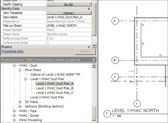
Figure 23.18 View properties for a title when a view is placed on a sheet
Adding Annotations
Annotation objects can be added directly to sheet views. You can place items such as north arrows, graphic scales, and other symbols directly on sheets in conjunction with viewports, title lines, or titleblock graphics. To place these items onto sheets, you use the Symbol button on the Annotate tab. Annotation objects on a sheet snap to titleblock geometry, but you cannot snap to title lines or schedule graphics other than the outline of a schedule. If you have an annotation, such as a north arrow symbol, that needs to be part of your view titles, it can be nested into your view title annotation family.
You can also add text directly to a sheet by using the Text tool on the Annotate tab. Plan notes or general notes can be typed directly on a sheet, or if you have a set of notes that is used on every project, you may want to put those notes in a drafting view so that they can be saved as a separate file or included in your project template. Another option is to put the notes in a legend view, which allows you to place the same notes on more than one sheet.
Placing Schedules
Schedules are placed on sheets in the same way as views, by dragging and dropping them from the Project Browser. When you place a schedule onto a sheet, it won't look the same as it does when the schedule view is open in the drawing area. The columns of a schedule can be resized on a sheet by using the triangular grips that appear at the top of each column-separation line. The height of each row adjusts to accommodate the amount of text within a cell when the column width is modified. The small grip that appears at the right side of a schedule allows you to split the schedule into an additional column if it is too long to fit on a sheet in a single column. Figure 23.19 shows that when you split a schedule, the headings are applied to each section.
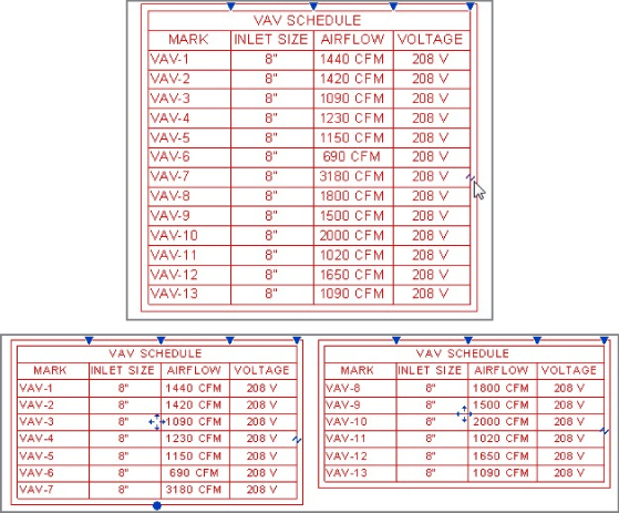
Figure 23.19 Splitting a schedule
A schedule can be split multiple times if necessary. The dot grip at the bottom of the first section of the schedule can be dragged up or down to control where the split occurs. To put a split schedule back together, click and drag one of the blue four-way arrow grips that you'll see in the center of a schedule's column onto another section of the schedule.
Schedules can be snapped to guide grid lines on a sheet by using the Move tool and snapping to the outline graphics of the schedule as the starting point. This can be useful for schedules that appear on multiple sheets, such as a Room schedule.
Using Sheet Lists
A sheet list is a schedule that displays project sheet information on a title sheet or any other sheet within your project. You create sheet lists in the same way as other schedules, and the parameters that are available apply only to sheet views. You can also use a sheet list to keep track of the information that is required on your sheets.
When you begin a project, you can create a sheet list and input projected sheets to estimate the contents of your construction document set. This is done by creating placeholder sheets in the sheet list. A placeholder sheet can be created by adding a new row to a sheet list schedule. With the sheet list open in the drawing area, click the Insert Data Row on the Rows panel to add a row. If a filter is applied to your sheet list, the new rows may not appear if they do not meet the filter requirements. A “working” sheet list—one that does not get put on a sheet but that shows all sheets and information—is a useful tool for sheet management. Another sheet list can be created to be placed on a title sheet for your construction documents.
The new row added to your sheet list has a sheet number that is the next in sequence with the last sheet that was created. Adding a row to the schedule does not create an actual sheet view, so the placeholder sheet does not appear in the Project Browser. Any of the parameters used in your sheet list can be given values for the placeholder sheet.
When the time comes to create the actual sheet that the placeholder represents, you can choose the placeholder sheet from the New Sheet dialog box, as shown in Figure 23.20. You must also choose a titleblock option for the sheet to be created.
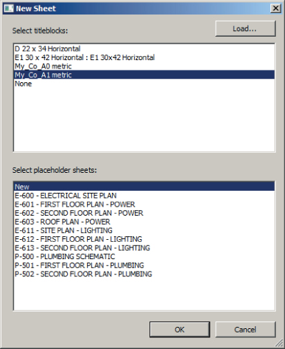
Figure 23.20 Choosing placeholder sheets in the New Sheet dialog box
When you have chosen the titleblock and placeholder sheet, clicking OK in the New Sheet dialog box creates the sheet. All the information that was entered into the sheet list for the placeholder sheet populates the appropriate labels in the titleblock of the sheet. The sheet now also appears in the Project Browser.
Using placeholder sheets is a good way to keep track of consultant sheets that are not part of your project file. For example, if you are working with a civil engineering consultant who is not using Revit, you can include a record of their drawings with placeholder sheets in your project to keep an accurate sheet count and sheet list.
Being able to create your project documents directly in the file that contains your model is a fundamental benefit of using Revit. Now that you have learned some of the skills required to create sheets, practice by completing the following exercise:
- Open the RMEP2016_
Ch23_Project.rvtfile found at this book's web page,www.sybex.com/go/masteringrevitmep2016. - Right-click Sheets in the Project Browser. Select the New Sheet option.
- Choose the My_Co_A1 metric titleblock in the New Sheet dialog box and click OK.
- Select the titleblock in the drawing area, and in the Properties palette, change Sheet Name to FIRST FLOOR PLAN – HVAC. Change Sheet Number to M-101. Click the Apply button in the Properties palette. Notice that the titleblock information is updated.
- Right-click Sheets in the Project Browser, and select the New Sheet option. Choose the My_Co_A1 metric titleblock and click OK.
- Repeat step 4, naming the sheet SECOND FLOOR PLAN – HVAC. Notice that the sheet name you entered in step 4 is available in the drop-down of the parameter. Each time you type in a name, it is stored in this list. You can pick a name from the list and modify it as needed for a new sheet. This helps keep names consistent and avoids typing errors. You do not have to edit the Sheet Number option because it was created automatically in sequence with the previous sheet.
- Open the M-101 sheet again. Click the Guide Grid button on the Sheet Composition panel of the View tab. You can either select the existing or create a new guide grid and click OK.
- Select the guide grid by clicking one of its outer edges. In the Properties palette, change the Guide Spacing parameter value to 4”(100mm).
- In the Project Browser, drag the HVAC First Floor floor plan view to the drawing area. Click to place the view anywhere on the sheet.
- Select the view, and click the Move button on the Modify | Viewports contextual tab. Click the intersection of grids 1 and A to start the move, and snap to the intersection nearest the top left of the titleblock, as shown in Figure 23.21.
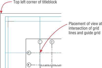
Figure 23.21 Alignment of grid lines to the guide grid
- Open the M-102 sheet, and drag the HVAC Raised Second Floor floor plan view onto the sheet. Click the Guide Grid button on the View tab, choose the existing Floor Plans guide grid, and click OK, as shown in Figure 23.22. Repeat step 10 to align the view to the guide grid.
1
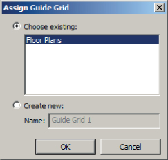
Figure 23.22 Assign Guide Grid dialog box
- Open the Sheet List schedule by double-clicking it in the Project Browser. Click the Insert Data Row button on the Rows panel of the ribbon. In the schedule, change Sheet Number to M-501 and Sheet Name to SECTIONS AND DETAILS for the new row.
- Right-click Sheets in the Project Browser and select the New Sheet option. In the New Sheet dialog box, select the M-501 SECTIONS AND DETAILS placeholder sheet and
click OK.
- Drag the Section 1 view from the Project Browser onto the sheet. Drag the DUCT DETAILS drafting view onto the sheet from the Project Browser.
- Select the detail view on the sheet. In the Properties palette, click the Edit Type button. In the Type Properties dialog box for the Viewport family, click the Duplicate button. Name the new family type No Title and click OK. In the Type Properties dialog box, change the Show Title parameter to No, as shown in Figure 23.23. Click OK in the Type Properties dialog box, and confirm that the detail viewport on the sheet has no title or line.
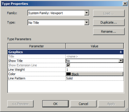
Figure 23.23 Viewport properties
- Right-click Sheets in the Project Browser and select the Browser Organization option. Select the check box next to the Sheet Prefix option. Click the Edit button. On the Grouping And Sorting tab, set the first Group By drop-down list to Sheet Number using one leading character, as shown in Figure 23.24.
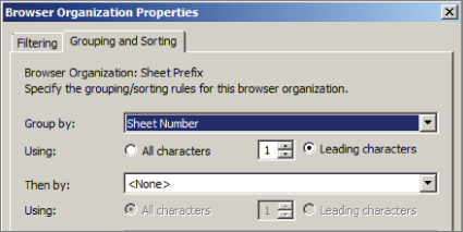
Figure 23.24 Browser organization setting
- Click OK to close all dialog boxes. Notice how the sheets are organized in the Project Browser.
Making Sheet Revisions
Revisions are part of nearly every project. You can keep track of revisions to a Revit project by using a revision schedule in your titleblock families and managing the revisions with Revit.
When you make a change to your model and you want to issue it as a revision, you can draw a revision cloud directly in the view, or the cloud can be drawn on the sheet displaying the view. Either way, you should first establish the properties of the revision. To create a revision in your project, click the Revisions button on the Sheet Composition panel of the View tab, shown in Figure 23.25. This tool can also be found on the Additional Settings button of the Manage tab, under Sheet Issues/Revisions.
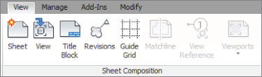
Figure 23.25 Sheet Composition ribbon panel
Do not confuse this with the Revision Cloud button on the Annotate tab, which is used to draw the actual cloud graphics. The Revisions button activates the Sheet Issues/Revisions dialog box, where you can define the revision and establish the behavior of the revision schedule and graphics. Figure 23.26 shows the dialog box. Notice the available settings for the numbering, which are Numeric, Alphabetic, or None if you do not want numbered revisions.
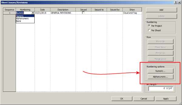
Figure 23.26 Sheet Issues/Revisions dialog box
New for Revit MEP 2016 is the ability to assign a prefix or suffix to the revision sequence, allowing you to have revisions more in keeping with industry standards such as
- Design Stage: A, B, C, D …
- Tender/bid Stage: T1, T2, T3 …
- Construction Stage: C1, C2, C3 …
These new settings are accessed from the Numbering Options as shown in Figure 23.26 with the different options shown in Figure 23.27.
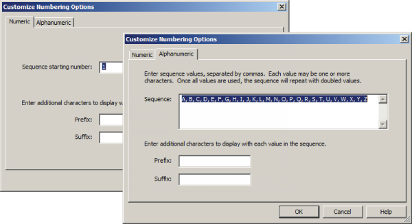
Figure 23.27 Revision numbering options
The settings on the right side of the dialog box allow you to number your revisions by sheet or by the entire project. Clicking the Add button in the upper-right corner creates a new revision sequence. The move buttons in the Row section enable you to move a revision up or down the list to change the order in which revisions appear in the schedule. The merge buttons allow you to combine the contents of one revision with another. Once you have created a revision sequence, it cannot be deleted. You must merge it with another revision. The Alphabetic Sequence setting can be defined to eliminate unwanted letters or establish a custom numbering system.
When you use the Per Sheet revision sequence setting, the revisions are listed as they occur on each sheet. So you could, for example, have a revision number 2 in your revision sequence that is the first revision to occur on a sheet. Therefore, it will be listed as number 1 in the revision schedule on the sheet and in its tag.
If you use the Per Project revision sequence setting, you can have a revision number 2 in your sequence, and if it is the only revision on a sheet, it will show up as number 2 in the schedule and its tag.
You can also change the Arc Length setting, which allows you to define the size of the arcs used to draw your revision clouds. The value you use for this setting will apply to all revision clouds, including those that have already been drawn. Use caution because this may affect existing revision clouds in an undesirable manner.
With the settings established for a revision, you can use the Revision Cloud button on the Detail panel of the Annotate tab to draw a cloud around the modified area. When you click the Revision Cloud button, it activates the Modify | Create Revision Cloud Sketch contextual tab. The Draw panel is available on this contextual tab and allows you to choose from various drafting tools to sketch a revision cloud. Press the spacebar to flip the orientation of the cloud bubble when drawing clouds. Be sure to select the green check mark on the Mode panel to finish creating the revision cloud and exit sketch mode. The properties of the cloud can be used to determine the revision sequence of which the cloud is a part. Figure 23.28 shows a revision cloud that was created on the contractual documentation (sheet M-501) and the resulting revision schedule where the view resides. Notice that the cloud has been tagged using a revision tag that reports the revision number.
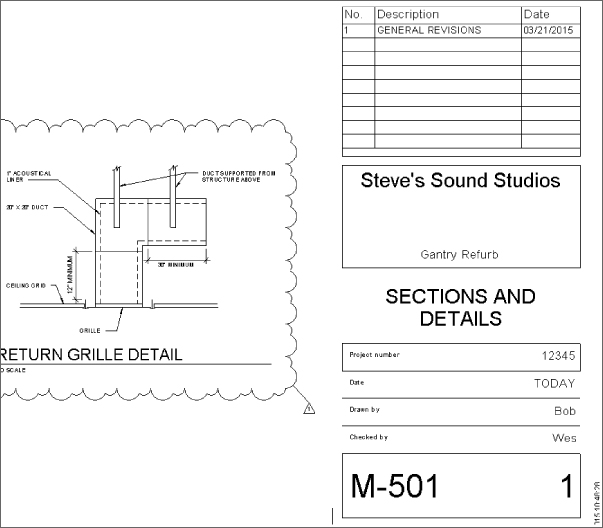
Figure 23.28 Revision cloud in a view
You can use the Issued parameter in the Sheet Issues/Revisions dialog box to establish that a revision has been issued. When a revision sequence has been marked as issued, you cannot add revision clouds to it. Sorting your revision schedule by sequence is a good way to organize your revisions. This allows you to use a custom numbering system without having to sort by it.
The visibility of revision clouds and their tags can be controlled via the Visibility/Graphic Overrides dialog box. Their categories are located on the Annotation Categories tab of the dialog box.
If you want to show a revision in the schedule of a sheet but that sheet does not contain a view with the revision, or the revision is not drawn on that sheet, you can do so by using the Revisions On Sheet parameter found in the Instance properties of the sheet. Click the Edit button and choose which revisions are to be shown in the revision schedule.
Printing Sheets
Although Revit has many features that allow you to visually verify the coordination of your design and documents, printing is still a necessary part of a Revit project workflow. There are so many types of printers and print drivers that it would be difficult, if not impossible, to describe print settings that would work for everyone on every project. The best thing that you can do to make your printing tasks easier and more efficient is to take a sample project and experiment with different print settings until you achieve the desired results.
Any of the views in your project can be printed, except for schedules. A schedule needs to be placed on a sheet so that it can be printed. Schedules can be exported to TXT files for use in and for printing by other software. Third-party applications also provide a way to get schedule data out of Revit, and back in if necessary.
Printing options are located on the Application menu, and clicking Print activates the Print dialog box shown in Figure 23.29. This dialog box allows you to establish the printer to be used, define the name and location when printing to a file, and define which views or sheets are to be printed.
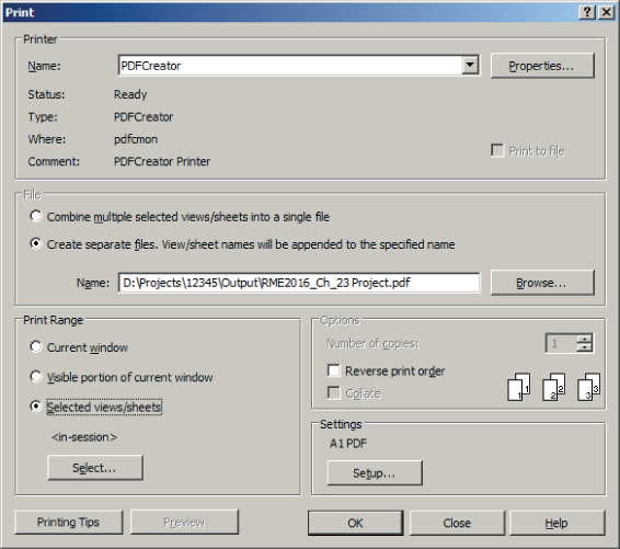
Figure 23.29 Print dialog box
Clicking the Setup button located in the Settings section activates the Print Setup dialog box shown in Figure 23.30, which can also be accessed via the Application menu. This dialog box contains settings for how the print appears on the paper or in the file.
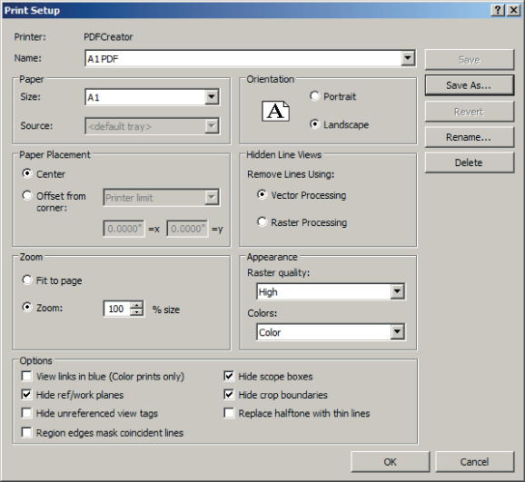
Figure 23.30 Print Setup dialog box
The Name drop-down list at the top is for saved print setups. Once you have established the settings that produce the desired print quality, you can save the setup for future use by clicking the Save button in the upper-right corner.
Vector or raster processing can be used for views set to Hidden Line. You may get varying degrees of quality depending on your printer drivers, so it is best to experiment with each option to determine the best one. For the Raster Processing option, you can choose the quality in the drop-down list in the Appearance section. The Colors drop-down in this section allows you to choose an option for color prints or black lines. The Grayscale option in this drop-down converts any color lines to their grayscale equivalent when printing to a black-and-white printer.
In the Options section at the bottom of the dialog box, you can hide certain types of objects, such as reference planes and view crop regions. There are also settings to hide section, callout, or elevation marks that reference views that are not placed on a sheet. This is useful because it eliminates the need to hide those objects individually in the views prior to printing. The option to replace any halftone lines with thin ones is a useful setting if your printer driver causes halftone lines to be too faint when printed.
With the settings established, clicking OK returns you to the Print dialog box (if that is where you accessed the Print Setup dialog box), where you can determine what is to be printed. In the Print Range section, you can choose to print what is currently visible in the drawing area or the currently open view, or you can select views and sheets to be printed. Clicking the Select button in this area activates the View/Sheet Set dialog box, which lists all the printable views and sheets, as shown in Figure 23.31.
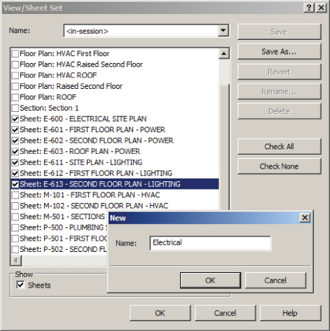
Figure 23.31 View/Sheet Set dialog box for printing
In this dialog box you can select the desired sheets or views to be printed. You can filter the list of available views and sheets to show only views or only sheets by using the check boxes at the bottom of the dialog box. Once you have chosen a set of views or sheets you can save the selection set for future use. The Name drop-down at the top of the dialog box lists all the saved selection sets.
Exporting Sheets
You can export your sheets to CAD or DWF format as an alternative to printing directly from Revit or to collaborate with clients and consultants who may not have the ability to view Revit files. You can find the Export options on the Application menu. There are many options for export, but for sharing sheets, the two that we will focus on are exporting to CAD and exporting to DWF. Selecting CAD Formats from the Export options and choosing a file format activates the Export CAD Formats–Views/Settings dialog box. Figure 23.32 shows this dialog box for the DWG file format.
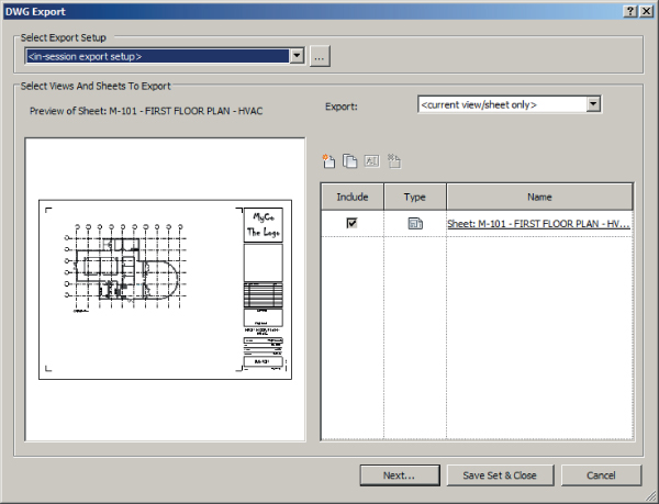
Figure 23.32 DWG Export dialog box
The Select Export Setup drop-down list at the top of the dialog box allows you to choose the export settings that you have established and saved.
The preview area of the dialog box shows the current view open in the drawing area. The right side of the dialog box is for choosing which sheets or views are to be exported. You can create a set of views and/or sheets by clicking the New Set icon. Once you give the set a name, all the printable views and sheets appear in the list. The drop-down at the top of the right side, shown in Figure 23.33, enables you to filter the list for specific types of views or sheets.
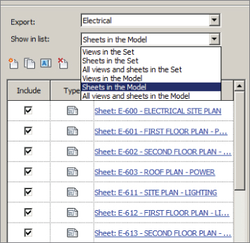
Figure 23.33 Export filter list
You can use the check boxes in the Include column of the list to determine which sheets or views will be exported. Once you are satisfied with the list, you can click the Save Set & Close button so that the next time you access the dialog box, it returns to the saved settings.
When you are ready, clicking the Next button allows you to browse to the location for the exported CAD file(s). The check box at the bottom of the window creates separate DWG files for each view that is on a sheet when you're exporting Revit sheets and they are linked to their corresponding sheet file as external references. You can specify a prefix to apply to the names of the files and also the file type, as shown in Figure 23.34.
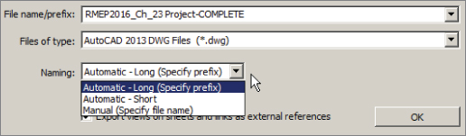
Figure 23.34 Export file naming options
The option to export sheets or views to DWF works in the same way as exporting to CAD, except additional options are available because of the capabilities of a DWF file to report element properties. In the DWF Export Settings dialog box, the DWF Properties tab allows you to export the properties of your Revit model elements and to access print settings prior to export. The Project Information tab gives you direct access to the project information contained in your Revit project. You can edit the parameters in this dialog box to update any project information, such as issue date, prior to export.
When you click the Next button, you can browse to a location for the DWF file. There is an option in the browse window to combine all the views and/or sheets to be exported into a single DWF file.
If you are sharing your sheets or views with someone who is unable to open a DWF file, you can export to DWFx format, which can be viewed by using the free XPS Viewer, available for download from Microsoft. The viewer is not able to view files containing 3D graphics, so it should be used only for 2D files. These files can also be shared with others via Autodesk® 360 hosted projects.
The Bottom Line
- Create a titleblock. A titleblock can be the signature for your projects. Its design and layout can be an immediate indicator of who has created the construction documents. A titleblock is also important for conveying general project and specific sheet information.
- Master It To ensure that your Revit projects look the same as, or similar to, your other projects, it is necessary to have a titleblock family that looks the same as other file format titleblocks you use. Describe the process for creating a Revit titleblock family from an existing CAD format titleblock.
- Establish sheets in your project. The sheets that make up your construction documents can be organized in your Revit projects for easy access and for management of project information.
- Master It A Sheet List schedule is a useful tool for managing the information shown on your construction documents as well as for organizing the order of sheets for your project. Is it possible to create parameters for sheets that can be used in the sheet list? Explain.
- Place views on sheets. For a Revit project, the construction documents are created as a result of the model, whereas in traditional CAD environments, the sheets are the main focus. You can put your construction documents together by placing the views you have created onto your sheets.
- Master It Uniformity among sheets in a document set is important not only to the look of a project but also for ease in document navigation. Explain how guide grids can be used to place model views in the same location on individual sheets.
- Print and export sheets. Although we live in a digital age, the need to print sheets and views is still part of our daily workflow. With the ability to work with consultants from all over the world, the need to share digital information is crucial. Exporting sheets and views to a file format that can be easily shared increases our ability to collaborate with consultants.
- Master It Printing sheets is often necessary for quality control of a project. How can you keep section and elevation marks of views that are not used on your sheets from printing?