APPENDIX A
PIC24 Architecture and Instruction Set Summary
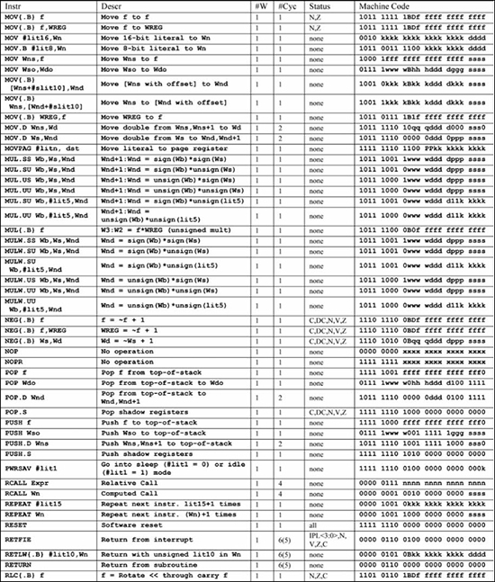
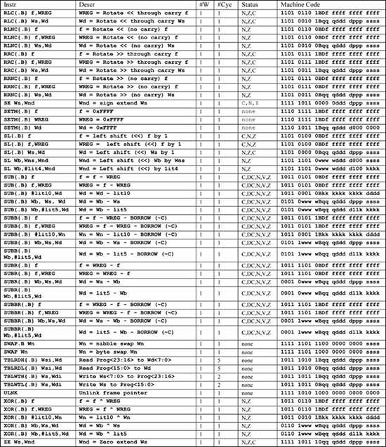
This appendix contains a summary of the PIC24 architecture and instruction set. Figures A.3 through A.10 give the instruction set summary, with Figures A.1 through A.2 providing symbols and encodings used in these summaries. The instruction set encodings and definitions are taken from the 16-bit MCU and DSC Programmer’s Reference Manual [5].
Register placeholder symbols used in instruction mnemonics are:
![]()
Wn: Register direct addressing; Wn specifies one of W0, W1, ... W15.
![]()
Wns: Register direct addressing; Wns specifies one of W0, W1, ... W15.
![]()
Wnd: Register direct addressing; Wnd specifies one of W0, W1, ... W15.
![]()
Wb: Register direct addressing; Wb specifies one of W0, W1, ... W15.
![]()
WREG: The working register, specifies W0 in file register instructions.
![]()
Ws: Register direct (Ws) and indirect addressing modes ([Ws], [Ws ++], [Ws --], [++ Ws], [-- Ws]); Ws specifies one of W0, W1, ... W15.
![]()
Wd: Register direct (Wd) and indirect addressing modes ([ Wd ], [ Wd ++], [ Wd --], [++ Wd ], [-- Wd ]); Wd specifies one of W0, W1, ... W15.
![]()
Wso: All of the addressing modes of Ws, with the additional mode of register offset indirect [Wso + Wb]; Wso specifies one of W0, W1, ... W15.
![]()
Wdo: All of the addressing modes of Wd, with the additional mode of register offset indirect [Wdo + Wb]; Wdo specifies one of W0, W1, ... W15.
![]()
Wsi: Indirect addressing modes ([Ws], [Ws ++], [Ws --], [++ Ws ], [-- Ws ]); Ws specifies one of W0, W1, ... W15. Used only by the tblrdl and tblrdh instructions.
![]()
Wdi: Indirect addressing modes ([Wd], [Wd ++], [Wd --], [++ Wd ], [-- Wd ]); Wd specifies one of W0, W1, ... W15. Used only by the tblwtl and tblwth instructions.
Figure A.1
Machine code symbols
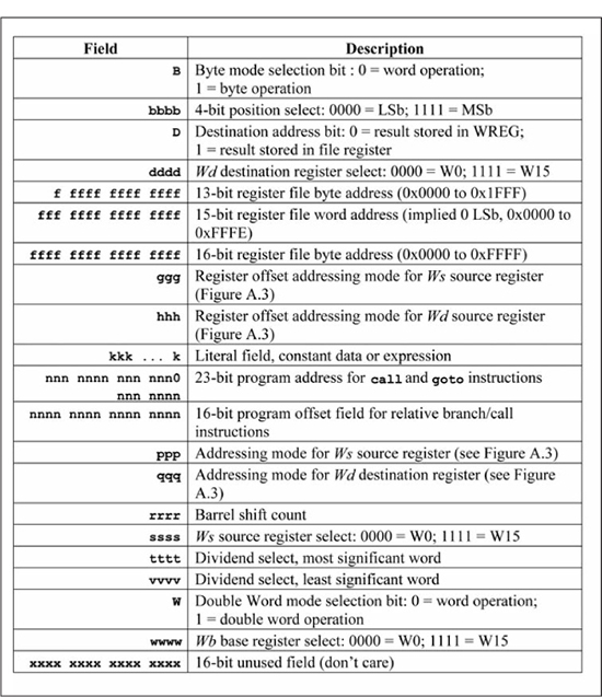
Figure A.2
Addressing mode encodings
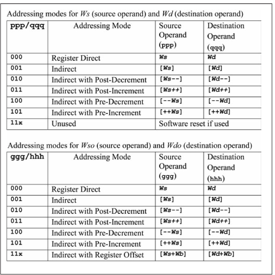
Figure A.3
Instruction table (part 1)
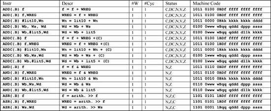
Figure A.4
Instruction table (part 2)
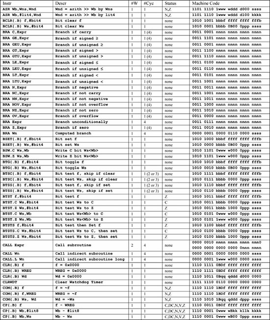
Figure A.5
Instruction table (part 3)

Figure A.6
Instruction table (part 4)