CHAPTER 7
ADVANCED ASSEMBLY LANGUAGE: HIGHER MATH
This chapter examines various higher math topics such as multiplication and division operations for unsigned and signed integers, floating-point number representation, saturating arithmetic, BCD arithmetic, and ASCII/binary conversions.
Learning Objectives
After reading this chapter, you will be able to:
![]() Implement signed and unsigned integer multiplication in PIC24 assembly language.
Implement signed and unsigned integer multiplication in PIC24 assembly language.
![]() Implement signed and unsigned integer division in PIC24 assembly language.
Implement signed and unsigned integer division in PIC24 assembly language.
![]() Discuss the formatting and storage requirements of single- and double-precision floatingpoint numbers.
Discuss the formatting and storage requirements of single- and double-precision floatingpoint numbers.
![]() Implement saturating addition and subtraction operations in PIC24 assembly language.
Implement saturating addition and subtraction operations in PIC24 assembly language.
![]() Implement BCD addition and subtraction operations in PIC24 assembly language.
Implement BCD addition and subtraction operations in PIC24 assembly language.
![]() Implement ASCII-to-binary and binary-to-ASCII for both hex and decimal number formats in PIC24 assembly language.
Implement ASCII-to-binary and binary-to-ASCII for both hex and decimal number formats in PIC24 assembly language.
Multiplication
In C, the multiplication operation is written as product = multiplicand * multiplier. For integer multiplication, the number of bits required for the product to prevent overflow is the sum of the bits in the multiplicand and multiplier. Typically, the two operands are the same size, so two n-bit operands produce a 2n-bit result. Figure 7.1 shows a paper and pen multiplication of two 3-bit operands that produces a 6-bit product. Starting with the rightmost bit of the multiplier, a partial product is formed by multiplying the multiplier bit with the multiplicand, with the rightmost bit of the partial product aligned under the multiplier bit that produced it. Since this is binary multiplication, a 1 in the multiplier produces a partial product that is equal to the multiplier, while a 0 produces a partial product of all zero bits. The product is formed from the sum of all of the partial products.
Figure 7.1
3 x 3 unsigned multiplication

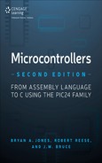
The multiplication operation can be implemented in numerous ways. The cheapest method in terms of logic gates is to not add any support for multiplication to the ALU, and to simply rely on pre-existing microprocessor add and shift operations to perform a multiplication. An algorithm for an unsigned integer multiplication using add/shifts is seen in Figure 7.2. The two n-bit operands are named mc (multiplier) and mp (multiplicand). The ph variable holds the accumulated sum of the partial products, and at algorithm termination, ph contains the upper n bits of the product. The algorithm loops n times, once for each bit of the multiplier (mp). On each loop iteration the LSb of mp is tested; if 1, the multiplicand is added to the ph variable. If the LSb of mp is 0, then addition is not performed as the partial product is zero in this case, making the addition superfluous. The shift right of the Cflag, ph, and mp values accomplishes two things:
![]() The LSb of the ph variable is a final bit of the product; shifting ph right moves this bit into the MSb of mp, saving this bit for the result.
The LSb of the ph variable is a final bit of the product; shifting ph right moves this bit into the MSb of mp, saving this bit for the result.
![]() The right shift moves the next bit of the multiplier (mp) into the LSb for testing at the top of the loop. As the loop iteration proceeds, each bit of the multiplier is examined from LSb to MSb.
The right shift moves the next bit of the multiplier (mp) into the LSb for testing at the top of the loop. As the loop iteration proceeds, each bit of the multiplier is examined from LSb to MSb.
After n iterations, the multiplication is finished and the loop is exited. The ph variable contains the upper n bits of the product, and mp the lower n bits. The ph variable is copied to the mc variable so that the final 2n-bit product returns in the original operands as mc:mp.
Figure 7.2
Unsigned add/shift integer multiplication algorithm
The disadvantage of the shift/add technique for multiplication is obvious—it is slow! An assembly language implementation requires several instruction cycles for each loop iteration assuming separate shift and add instructions. If hardware support for the shift/add iteration is added to the ALU in the form of a double-length shift register for the product and specialized loop control, this can be reduced to one clock cycle per loop iteration (eight clock cycles). While this would be an improvement, a faster method is to augment the ALU with a specially designed multiplier unit such as an array multiplier that produces the result in one clock cycle. Figure 7.3 shows a naive implementation of a 3 x 3 array multiplier that performs the operation of Figure 7.1. There are more efficient methods for constructing array multipliers, but this conveys the key point of an array multiplier: the product is available as a combinational delay after the inputs are applied. This means the multiplication is completed in one clock cycle (if the clock cycle is long enough). The origin of the term array multiplier is obvious from Figure 7.3, as it is built from an array of full adders and half adders that implements the addition of the partial products. Observe that binary multiplication for each partial product bit is simply an AND gate, as the Boolean multiplication a * b is a 1 only if both inputs are 1.
Figure 7.3
Naive 3 x 3 unsigned array multiplier

The array multiplier of Figure 7.3 implements unsigned multiplication; there are iterative and array multiplier architectures [3, 4] that implement signed multiplication assuming two’s complement encoding. The PIC24 has a 16 x 16 array multiplier that accepts both signed and unsigned operands and produces either a 16-bit or a 32-bit result, depending on the variant of instruction (MULW or MUL). Figure 7.4 shows the various PIC24 multiplication instruction forms. The three-operand register addressing forms implement a 16 x 16 multiplication and support the four possible variations of unsigned/signed operands for the multiplicand/multiplier operands. The 32-bit product variant is written to the Wnd+1:Wnd register pair, with Wnd containing the least significant word and Wnd+1 the most significant word. The mul{.b} f instructions implement either a 16 x 16 or 8 x 8 unsigned multiplication, with the 32-bit product written to W3:W2, and the 16-bit product to W2. The literal forms implement a 16 x 16 multiplication using an unsigned 5-bit literal (#lit5) as the multiplier with either an unsigned or signed multiplicand in Wb, with the 32-bit result placed in the Wnd+1:Wnd register pair. For any 32-bit product, the destination register for the least significant word (Wnd) must be an even-numbered register and may not be W14.
Figure 7.4
PIC24 multiplication instruction forms

Listing 7.1 shows several multiplication examples that illustrate the differences between unsigned and signed operands. Register W0 has the 16-bit value 0xFFFF, which is 65,535 as an unsigned integer, and –1 as a two’s complement integer. Register W1 has the 16-bit value of 0x0001, which is 1 as an unsigned integer and +1 as a two’s complement integer. Observe that the mul.uu instruction treats both input operands as unsigned, performing 65,535 * 65,535 for a result of 4,294,836,225, or 0xFFFE0001. The W0, W0, W2mul.ss instruction treats both input operands as signed, performing –1 * –1 for a result of +1, or 0x00000001.W0, W0, W4
Listing 7.1: Multiplication Instruction Examples
(1) mov #0xFFFF,W0; 65535 unsigned, -1 signed (2) mov #0x1, W1 ; 1 unsigned, +1 signed (3) mul.uuW0, W0, W2 ; 65535 * 65535 = 4294836225 = 0xFFFE0001 = W3:W2 (4) mul.ssW0, W0, W4 ; -1 * -1 = +1 = 0x00000001 = W5:W4 (5) mul.uuW0, W1, W6 ; 65535 * 1 = 65535 = 0x0000FFFF = W7:W6 (6) mul.ssW0, W1, W8 ; -1 * +1 = -1 = 0xFFFFFFFF = W9:W8 (7) mul.uuW0, #1, W10 ; 65535 * 1 = 65535 = 0x0000FFFF = W11:W10 (8) mul.suW0, #1, W12 ; -1 * 1 = -1 = 0xFFFFFFFF = W13:W12
64-Bit Multiplication
The shift/add approach of Figure 7.2 is scaleable, in that it can be applied to any size operand. One method for using the 16 x 16 hardware multiplication of the mul instruction for a 32 x 32 multiplication to produce a 64-bit product is shown in Figure 7.5, with s and r containing the 32-bit operands. Four 32-bit partial products are formed using 16 x 16 multiplications as pp0=sL*rL, pp1=sL*rH, pp2=sH*rL, and pp3=sH*SL, where {sL, rL} and {sH, rH} are the lower and upper words of the 32-bit operands s and r. Observe that the partial products pp1 and pp2 are shifted to the left such that the lower words of these 32-bit partial products align with the upper word of pp0; the lower word of pp3 is aligned with the upper words of pp1 and pp2. When you’re performing the word additions of the partial products, take care to propagate the carries across all partial products during the summation.
Figure 7.5
Unsigned 32 x 32 multiplication using 16 x 16 multiplications

A subroutine named mult32x32_uns that implements the 32 x 32 multiplication of Figure 7.5 is given in Listing 7.2. The s and r 32-bit input operands are passed in W1:W0 and W3:W2, respectively. The 64-bit result is passed back in W3:W2:W1:W0 as per the working register usage policy established in Chapter 6. All four partial products are computed first using mult.uu instructions, with a register usage of pp0=W5:W4, pp1=W7:W6, pp2=W9:W8, and pp3=W11:W10. Additions using add and addc instructions then implement the sums of the upper and lower words of the partial products, as per Figure 7.5.
The addc instructions are used to propagate carries all the way to the upper word of pp3. The main code of Listing 7.2 shows a sample call to the mult32x32_uns subroutine. To improve the readability of the code, registers used are given symbolic names taken from Figure 7.5. For example, the two statements sL = W0 and sH = W1 cause instances of sL and sH to be replaced with W0 and W1 as the code is assembled.
Listing 7.2: Unsigned 32 x 32 Bit Multiplication
main:
      mov #0xFFFF, W0  ;
      mov #0xFFFF, W1  ; s = W1:W0 = 4294967295
      mov #0xFFFF, W2  ;
      mov #0xFFFF, W3  ; r = W3:W2 = 4294967295
      call mult32x32_uns
;;W3:W2:W1:W0 = 0xFFFFFFFE00000001 = 18446744065119617025
done:                       ;do not return
       bra done

; p = s * r, where:
; W1:W0 = s
sL = W0
sH = W1
; W3:W2 = r
rL = W2
rH = W3
; Use W4-W11 to store low and high words of partial products 0-3
pp0L = W4
pp0H = W5
pp1L = W6
pp1H = W7
pp2L = W8
pp2H = W9
pp3L = W10
pp3H = W11
; 64-bit result in p = W3:W2:W1:W0 (p3:p2:p1:p0)
p0 = W0
p1 = W1
p2 = W2
p3 = W3
mult32x32_uns:
     push W8
     push W9

     push W10
     push W11
     mul.uu  sL, rL, pp0L  ; sL*rL = pp0
     mul.uu  sL, rH, pp1L  ; sL*rH = pp1
     mul.uu  sH, rL, pp2L  ; sH*rL = pp2
     mul.uu  sH, rH, pp3L  ; sH*rH = pp3
     mov  pp0L, p0          ; p0 = pp0L
     add  pp0H, pp1L, p1   ; p1 = pp0H + pp1L
; now propagate carry all the way up to p3 word
     addc pp1H, pp2H, p2   ; p2 = pp1H + pp2H + cout(pp0H + pp1L)
     addc pp3H, #0, p3     ; p3 = pp3H + 0 + cout(previous sum)
; next sum
     add  p1, pp2L, p1     ; p1 = pp2L + (p1 = pp0H + pp1L)
; now propagate carry all the way up to p3 word
     addc p2, pp3L, p2     ; p2 = pp3L + (p2 = pp1H + pp2H) + cout(previous_sum)
     addc p3, #0, p3       ; p3 = p3 + 0 + cout(previous_sum)
; 64-bit result p3:p2:p1:p0
     pop W11
     pop W10
     pop W9
     pop W8
     return
A signed 32 x 32 bit multiplication can be implemented using the mult32x32_uns subroutine of Listing 7.2 by first converting each negative operand to a positive number, performing the unsigned multiply, and then negating the product by subtracting it from 0 if either of the operands was originally negative.
Sample Question: What does the product 0x3A * 0xA8 return if the numbers are 8-bit unsigned? 8-bit signed? (two’s complement)
Answer: As unsigned numbers, the product is 0x3A * 0xA8 = 58 * 168 = 9,744 = 0x2610.
As signed numbers, the product is 0x3A * 0xA8 = +58 * (–88) = –5,104 = 0xEC10.
Division
Equation 7.1 represents the division operation, where p is the dividend, q is the quotient, d is the divisor, and r is the remainder.
The relationship between q, r, p, and d is more clearly expressed by Equation 7.2.
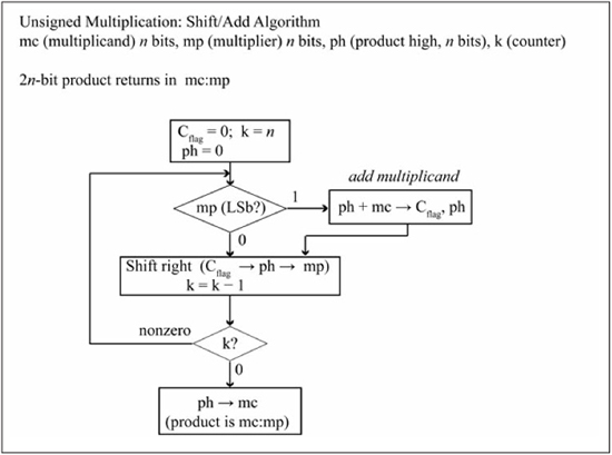
Implementations of the division operation typically use a 2n-bit dividend, an n-bit divisor, and produce an n-bit quotient and n-bit remainder. Figure 7.6 shows a paper and pen division of an 8-bit dividend by a 4-bit quotient, producing a 4-bit quotient and a 4-bit remainder. The subtraction performed at each step produces a partial dividend, which forms the dividend for the next stage. The last subtraction produces the remainder, which is guaranteed to be in the range 0 to d–1. Unlike multiplication, overflow can occur if the quotient requires more than n bits, which is true if the value formed by the upper n bits of the dividend is greater than or equal to the divisor.
Figure 7.6
Unsigned division (8-bit dividend, 4-bit quotient)
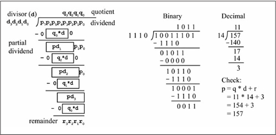
Several iterative division algorithms use shift/subtract operations to produce the quotient and remainder. Figure 7.7 shows the restoring division algorithm [3] for a 2n-bit dividend p and an n-bit divisor d. The high and low bytes of p are designated as pH and pL, respectively. On algorithm entry, the comparison pH >= d is performed to check for overflow; if true, the carry flag is set to 1 and the algorithm terminates. Like the add/shift multiplication algorithm, the main loop performs n iterations, with each iteration determining a quotient bit. A quotient bit is 1 if the partial dividend Cflag,pH >= d, in which case the new partial dividend is pH-d. A quotient bit is 0 if Cflag,pH < d, and the partial dividend remains the same. The first operation of the loop performs the shift Cflag←pH←pL, moving the partial dividend into the Cflag and upper n bits of pH. If the shift produces a carry, the partial dividend is greater than the divisor, so the new partial dividend is computed as pH-d→pH and the quotient bit is set to 1 (the LSb of pL is the current quotient bit). If no carry is produced by the shift, the subtraction pH-d→pH is performed, which has two side effects: a) the comparison d>pH is determined by the state of the Cflag, and b) the new partial dividend is computed. If Cflag is a 1, this indicates that no borrow occurred, so pH >= d, the new partial dividend is valid, and the quotient bit is set to 1. If Cflag is a 0, a borrow occurred, so pH < d, meaning the partial dividend should have been left undisturbed. In this case, the operation pH+d→pH is performed to restore the partial dividend to its original value and the quotient bit is cleared to 0. This action of performing the subtraction pH-d→pH and then restoring the partial dividend, if necessary, is why this algorithm is called restoring division. When the loop terminates after n iterations, the quotient is contained in pL and the remainder in pH.
Figure 7.7
Unsigned restoring division algorithm
There are faster iterative methods for division that use a multiplication operation in producing the quotient and remainder, but these require considerably more logic gates because an array multiplier is needed in the implementation. One method for accomplishing signed division is to convert the dividend and divisor to positive numbers, performing the unsigned division, then post-correct the sign of the quotient and remainder. If either of the original operands is negative, the quotient is negated. If the original dividend is negative, the remainder is negated. Unlike multiplication, if a microprocessor has an explicit integer division instruction, such as a 16-bit/8-bit operation, it is not possible to use this instruction in the implementation of a larger operation such as a 32-bit/16-bit division. As such, some microprocessors offer different sized integer division operations such as 16-bit/8-bit, 32-bit/16-bit, and 64-bit/32-bit.
Figure 7.8 shows the PIC24 division instruction forms. Both signed and unsigned 16-bit/16-bit and 32-bit/16-bit operations are available. In all cases, the 16-bit quotient and 16-bit remainder return in the W0 and W1 registers, respectively. The divisor (Wn) register must be contained in registers W2 or higher, as the dividend (Wm) is copied to registers W0 and W1 at the beginning of the operation. The W1 register either contains the most significant word of the 32-bit dividend for the 32-bit/16-bit operation, or the sign-extended or zero-extended most significant word of the 16-bit dividend for the 16-bit/16-bit operation. The N and Z flags reflect the status of the remainder. The V flag is set on overflow, which occurs if the quotient exceeds the 16-bit range. The C flag is used during the division operation and thus its final value is operand dependent. Division by zero causes an arithmetic trap (see Chapter 9 for a complete discussion of traps and interrupts).
Figure 7.8
PIC24 multiplication instruction forms

Listing 7.3 shows some division examples. The division instruction must be preceded by a repeat #17 instruction, which repeats the division instruction 17 + 1 = 18 times, as the division instruction requires 18 iterations to complete for both the 32-bit/16-bit and 16-bit/16-bit varieties. This means that 19 instruction cycles are required for division, which includes the instruction cycle for the repeat #17 instruction. The divisions of lines 8, 10, and 12 are signed divisions that change the sign of the operands, but keep their magnitudes the same. The remainder’s sign is the same as the dividend, and the quotient’s sign is positive if both operands have the same sign and negative otherwise. The division of line 17 shows an overflow example for an unsigned 32-bit/16-bit operation using the operands 65,536/1; the quotient of 65,536 exceeds the maximum unsigned 16-bit value of 65,535. The division of line 21 shows an overflow example for a signed 16-bit/16-bit operation using the operands –32,768/–1; the quotient of +32,768 exceeds the maximum positive 16-bit value of +32,767.
Listing 7.3: Division Examples
main: (1)       mov #0x9A00, W2 ; 39,424 unsigned, -26,112 as signed
(2)       mov #0x6600, W3       ; 26,112 unsigned, +26,112 as unsigned
(3)       mov #105, W4          ; 105 unsigned, +105 signed
(4)       mov #0xFF97, W5       ; 65,431 unsigned, -105 signed
(5)       repeat #17
(6)       div.u W2, W4          ; 39,424/105 = 375 = W0, r = 49 = W1
(7)       repeat #17
(8)       div.s W2, W4          ; -26,112/+105 = -248 = W0, r = -72 = W1
(9)       repeat #17
(10)      div.s W3, W5          ; +26,112/-105 = -248 = W0, r = +72 = W1
(11)      repeat #17
(12)      div.s W2, W5  ; -26,112/-105 = +248 = W0, r = -72 = W1
(13)      mov #0x0, W6
(14)      mov #0x0001, W7       ; W7:W6 = 0x00010000 = 65,536 double word
(15)      mov #0x01, W8 ; W8 = 1
(16)      repeat #17
(17)      div.ud W6, W8         ; 65,536/1 is overflow as quotient > 16-bits
(18)      mov  #0x8000, W2      ; -32,768 signed
(19)      mov  #0xFFFF, W3      ; -1 signed
(20)      repeat #17
(21)      div.s W2, W3          ; -32,768/-1 is overflow since +32,768 > 16-bits
Sample Question: What does the 16-bit/16-bit operation 0x9EF0/0x018D return for the div.u operation? For the div.s operation?
Answer: The div.u operation treats its operands as unsigned numbers, so 0x9EF0 = 40,688 and 0x018D = 397. The division 40,688/397 produces values of 102 (quotient) and 194 (remainder). In hex, this is 0x0066 and 0x00C2. As a check, quotient * divisor + remainder = dividend, or 102 * 397 + 194 = 40,688.
The div.s operation treats its operands as signed numbers, so 0x9EF0 = –24,848 and 0x018D = +397. The division –24,848/+397 produces values of –62 (quotient) and –234 (remainder). In hex, this is –62 = 0xFFC2, –234 = 0xFF16. As a check, quotient * divisor + remainder = dividend, or (–62) * (+397) + (–234) = –24,848.
Fixed-Point and Saturating Arithmetic
Up to this point, you have viewed binary integers as having the decimal point always located to the right of the least significant bit. The formal name for this type of representation is fixed-point, because the decimal point is fixed to a particular location. The decimal point can be positioned in any location within the binary number, as long as the application is consistent about where the decimal point is located. A fixed-point binary number is said to have the format x.y, where x is the number of digits to the left of the decimal point (integer portion) and y is the number of digits to the right of the decimal point (fractional portion). The integer portion of the number has a range of 0 to 2x –1, while the fractional range is 0 to (1–2–y). This gives a number range of 0 to (2x –2–y). The 8-bit unsigned integer representation used to this point has thus been 8.0 fixed-point numbers, which has a number range of 0 to 255. Moving the decimal point all the way to the left gives a 0.8 fixed-point number that has a number range of 0 to (20 –2–8), or 0 to approximately 0.9961. A 6.2 fixed-point number has a number range of 0 to (26 –2–2), or 0 to 63.75. Table 7.1 shows examples of different 8-bit fixed-point formats.
Table 7.1: Sample Fixed-Point Formats

Decimal to x.y Binary Format
The easiest method for converting an unsigned decimal number to its fixed-point representation is to multiply the number by 2y, then convert the integer portion to binary. If the remaining fraction after the multiplication by 2y is non-zero, then the resulting number is an approximation of the original number. Obviously, the more bits used for y in the x.y format, the better the approximation.
Another method is to convert the integer and fractional portions separately, with the conversion of the fractional portion f done bit-by-bit through an iterative method. The iterative process performs the comparison f • 2 ≥ 1; if this is true, the new binary digit is 1 and the new fractional part is f ← (f • 2) – 1. If f • 2 ≤ 1, the new binary digit is 0 and the new fractional part is f ← f • 2. The binary digits of the fractional part are determined left to right (most significant to least significant). The process stops when y binary bits of the final x.y binary result have been computed.
Sample Question: Convert 13.365 to a binary 8-bit number in 4.4 fixed-point format.
Answer: Multiplying 13.365 by 24 (16) produces 213.84. Truncating to 213, and converting to binary gives 0b11010101, or 0xD5.
The following steps show the iterative method for converting the fractional portion 0.365 to its 4-bit binary representation.
1. 0.365 * 2 = 0.73, which is < 1. The first (leftmost) binary digit is 0, and the new f is 0.73.
2. 0.73 * 2 = 1.46, which is > 1. The second binary digit is 1, and the new f is 1.46 – 1 = 0.46.
3. 0.46 * 2 = 0.92, which is < 1. The third binary digit is 0; the new f is 0.92.
4. 0.92 * 2 = 1.84, which is > 1. The fourth and last binary digit is 1.
Thus, the 4-bit representation of the fractional portion is 0b0101, and the complete number is 0b11010101, or 0xD5.
x.y Binary Format to Decimal Conversion
An unsigned fixed-point binary number is converted to decimal by multiplying each bit by its appropriate binary weight. The fractional bits have weights 2–1, 2–2, ... 2– y going from leftmost bit to rightmost bit. Another method is to view the n-bit number as an n.0 fixed-point number and divide that number by 2y to get the x.y decimal value. Observe that dividing by 2y is the same as shifting the n.0 fixed-point number to the right by y positions.
Sample Question: Convert 0xD5, an unsigned 4.4 binary number, to its decimal value.
Answer: The value 0xD5 is 0b11010101, so the integer portion is 1101, or 13. The fractional portion 0101 is (left to right):
0*2–1 + 1*2–2 + 0*2–3 + 1*2–4 = 0 + 0.25 + 0 + 0.0625 = 0.3125.
Thus, 0xD5, an unsigned 4.4 binary number, is 13.3125. Note that the value 0xD5 was the result obtained in the previous sample problem when converting 13.365 to a 4.4 binary format. This indicates the approximation that occurs in the decimal to fixed-point binary conversion because of the limited number of bits in the fractional portion. An alternate method is to note that 0xD5 is the value 213 as an 8.0 fixed-point number and compute 213/24 = 213/16 = 13.3125.
Signed Fixed-Point
Two’s complement x.y fixed-point numbers have a range of +(2x–1 –2–y) to –2x–1. Thus, an 8.0 format has a range +(27 –2–0) to –27, or +127 to –128. A 6.2 format has a range of +(25 –2–2) to –25, or +31.75 to –32.0, while a 1.7 format has a range of +(20 –2–7) to –25, or +0.9921875 to –1.0. Conversion of x.y two’s complement fixed-point in binary can be done by viewing the number as an (x + y).0 number, computing its decimal magnitude by the two’s complement binary to decimal conversion rules of Chapter 5, then dividing the number by 2y. A signed decimal number can be converted to its x.y binary format by multiplying the number by 2y, then converting the integer portion to binary.
Sample Question: Convert –3.25 to a binary number in 4.4 fixed-point format.
Answer: Multiplying –3.25 by 24 (16) produces –52, which is 0xCC in two’s complement. Thus, –3.25 in 4.4 signed fixed-point format is 0xCC.
Sample Question: What is the decimal value of 0xD5 if this represents a 4.4 signed fixed-point number?
Answer: The value 0xD5 converted to an integer decimal two’s complement number is –43. Dividing –43 by 24 (16), gives the final value of –2.6875. Observe that this is not the same decimal value obtained for 0xD5 when it was previously viewed as a 4.4 unsigned fixed-point number (the decimal value was 13.3125), which is obvious given that the signed decimal value must be negative since the most significant bit of 0xD5 is a 1. Also, the decimal value of 13.13125 exceeds the range of a signed 4.4 fixed-point number, which is +7.9375 to –8.0.
0.n Fixed-Point Format and Saturating Operations
In the coverage of the multiplication operation, you may have noticed a troubling problem: to prevent overflow, the size of the operands has to keep doubling! For example, an 8 x 8 multiplication produces a 16-bit product. If this value is then used in a subsequent 16 x 16 multiplication operation, a 32-bit product is produced. Note that the product size doubles again to 64 bits if the previous 32-bit product is used in a 32 x 32 multiplication. Obviously, it is not possible to keep doubling the size of the operands in each multiplication, so eventually an n-bit value must be used to hold the result of an n x n bit multiplication. If the operands are viewed as unsigned integers between 0 and 2n–1, overflow occurs if the upper n-bit value of the actual 2n-bit product is non-zero. When overflow does occur, for multiplication, addition, or subtraction, what can be done about it? In some cases, it is sufficient to simply set an error flag and let the higher-level application code deal with the problem. In other cases, such as real-time digital signal processing applications like audio or video data manipulation, there is no way to halt the system to “fix” the overflow problem. One approach to keep functioning in the presence of overflow is to produce a value that is a reasonable approximation of the correct answer. The 0.n unsigned fixed-point format is often used for data in digital signal processing applications, because of its advantages in regard to multiplication overflow and using the same sized operands for all operations. Numbers in 0.n unsigned fixed-point format have the range [0,1) (up to 1 but not including 1), where the maximum value gets closer to 1 as n increases. When two 0.n unsigned fixed-point numbers are multiplied, the upper n bits of the 2n-bit product are kept, while the lower n bits are discarded to keep the resulting product size as n bits. The lower n bits of the 0.2n product that are discarded are the least significant bits, which are the bits that one wants to be discarded if precision has to be limited. With the 0.n unsigned fixed-point representation, the multiplication operation cannot overflow, because the result is always in the range [0,1). Also, while the result is not the exact product since bits have been discarded, it is a good approximation of the correct product.
It would be nice to have addition and subtraction operations that performed in a similar manner with regard to overflow; that is, when overflow occurs, a value is returned that is a close approximation of the correct result. Saturating addition and subtraction operations clip results to maximum and minimum values in the presence of overflow or underflow. Figure 7.9 shows examples of unsigned saturating addition and subtraction for 8-bit numbers. On unsigned overflow (carry-out of the most significant bit), the result is saturated to all 1s, which is the maximum unsigned value. On unsigned underflow (borrow from the most significant bit), the result is clipped to the minimum value of zero. It is clear that the unsaturated results are nonsensical when overflow occurs, while the saturated results return the closest possible approximation given the range limits.
Listing 7.4 shows assembly code for a sat_add subroutine that implements W0 = W0 + W1add instruction, the setm instruction is used to set the W0 result to all 1s. Signed saturating addition clips values to either the maximum positive value or maximum negative value on two’s complement overflow. Some microprocessors, especially those touted as being especially suited for digital signal processing applications, have specialized instructions that directly implement saturating arithmetic; Microchip’s dsPIC® microcontroller family provides one example. The C language does not have saturating arithmetic operators or data types, and thus saturating arithmetic must be implemented as a specialized library of function calls.
Figure 7.9
Unsigned saturating addition/subtraction examples

Listing 7.4: Assembly Code for Unsigned Saturating Addition
; Do saturating word additionW0= sat_add(W0+W1) sat_add: addW0, W1,W0bra NC, sat_add_1 setmW0sat_add_1: return
Sample Question: What does the sum 0xA0 + 0x90 equal as a saturated unsigned addition? As a saturated signed addition?
Answer: With binary addition, the sum 0xA0 + 0x90 = 0x30, with C = 1, V = 1. As a saturated unsigned addition, the result clips to the maximum unsigned value of 0xFF because unsigned overflow occurred (C = 1). As a saturated signed addition, the result clips to the maximum signed negative value of 0x80 because two negative numbers were added and the two’s complement overflow occurred (V = 1).
The dsPIC® Microcontroller Family
The dsPIC® microcontroller family as represented by the dsPIC30F/dsPIC33F product lines implements a superset of the PIC24 instruction set. The dsPIC μC family preceded the PIC24 μC family in terms of release dates, and includes a separate arithmetic logic unit (ALU) that supports saturating operations on two’s complement fixed-point numbers in 16-bit, 32-bit, and 40-bit operand sizes. The additional dsPIC instructions that are not supported by the PIC24 μC are all instructions that are executed by this specialized ALU. Some of the saturating operations supported by this ALU are add, subtract, multiply to accumulator, square to accumulator, multiply-accumulate, multiply-subtract, and square-accumulate. The accumulator is a special-purpose register that allows a multiplication product to be added or subtracted from the accumulator contents in the same instruction. Many digital signal filter architectures are implemented more efficiently when this operation type is provided. Coverage of these additional instructions is beyond the scope of this text; check out the 16-bit MCU and DSC Programmer’s Reference Manual [5] for more details.
Floating-Point Number Representation
Fixed-point representation forces an application to determine a priori the number of bits to devote to the integer and fractional parts. More bits used for the integer portion means less precision for the fractional part and vice versa. A floating-point (FP) representation encodes an exponent field in the binary encoding, removing the need to allocate a fixed number of bits for the integer and fractional representation. This section gives a brief overview of floating-point number encoding and floating-point number operations in microprocessors; a more detailed discussion is found in [6].
IEEE 754 Floating-Point Encoding
Many different encodings for floating-point numbers have been proposed and used over the years, but in 1985, after a long review process, the IEEE 754 Standard for Binary Floating-Point Arithmetic was approved. Figure 7.10 shows the formats for single and double precision floating-point numbers in IEEE 754 format. The single precision format is 32 bits, while the double precision format is 64 bits. Each encoding is divided into sign, exponent, and significand fields.
The use of the fields of Figure 7.10 to produce a floating-point number is given in Equation 7.3.
This is a signed magnitude encoding, so the most significant bit is the sign bit, which is 1 if the number is negative and 0 if positive. The significand field (also known as the mantissa) determines the precision of the floating-point number. You can view the significand as encoding both the integer and fractional parts of the floating-point number. The exponent field determines the range of the floating-point number. For the single precision format, the exponent field is 8 bits and is encoded in bias 127, which means that 127 has to be subtracted from the field value to determine the actual exponent. This allows exponents to be compared using an unsigned comparison, which takes fewer logic gates for implementation and can have less delay than a signed comparison. For normal floating-point numbers, the exponent codes 0x01 through 0xFE are allowed. The exponent encodings 0x00 (all 0s) and 0xFF (all 1s) are reserved for so-called special numbers, discussed later in this section. Thus, the exponent range for single precision, IEEE 754 floating-point numbers is 2+127 (10+38) to 2–126 (10–38). The double precision format uses an 11-bit exponent field, with a bias value of 1023. The exponent range for double precision, IEEE 754 floating-point numbers is 2+1023 (10+307) to 2–1022 (10–308). In the C language, the float and double types are used for single precision and double precision floating-point variables, respectively. The MPLAB ASM 30 assembler supports specification of floating-point values using the .double and .single assembler directives, for double precision and single precision encodings, respectively.
Figure 7.10
Single precision and double precision FP formats

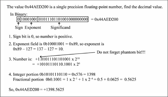
Figure 7.11 shows an example of converting a decimal number to its single precision, floating-point number representation. First, the decimal number is converted to its binary representation by converting the integer and fractional parts to binary. The binary number is then normalized to the form of Equation 7.3 by shifting the number to the left or right. Each time the number is shifted to the left (multiplied by 2), the exponent is decremented by 1. Each time the number is shifted to the right (divided by 2), the exponent is incremented by 1. Observe that the 1 to the left of the decimal point in Equation 7.3 is not encoded in the significand; it is understood to be in the encoding. This is often referred to as the phantom one bit, and provides an extra bit of precision to the significand without having to provide space for it in the significand field.
Converting a binary value in single precision FP format to its decimal representation is done by simply converting each component of Equation 7.3 to its decimal representation and multiplying as seen in Figure 7.12. The most common error in this conversion is to forget to add the phantom one bit to the significand.
Figure 7.11
Decimal to single precision FP format conversion

Figure 7.12
Single precision FP format to decimal conversion
The all-ones and all-zero exponent encodings are reserved for special number encoding. Special numbers are zero, positive/negative infinity (±∞), and NaN (Not a Number). Table 7.2 gives the encodings for special numbers. Infinity is produced when anything is divided by zero. A NaN is produced by invalid operations, such as zero divided by zero, or infinity minus infinity.
Table 7.2: Special Number Encodings
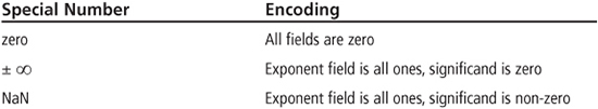
Sample Question: What does the 32-bit value 0xFF800000 represent as a single precision floating-point number?
Answer: The value is 0xFF800000 = 0b1111 1111 1000 0000 0000 0000 0000 0000.
Grouping this into fields produces sign bit = 1, exponent = 1111 1111, significand is all zeros. By Table 7.2, this value is –∞ (negative infinity).
Floating-Point Operations
A complete discussion of the implementation of floating-point arithmetic is beyond the scope of this book. To provide a glimpse at what is involved in performing floating-point arithmetic, the basic steps required to perform a floating-point addition are given in Table 7.3. The hardware required to support floating-point operations is much more complex than fixed-point arithmetic. Speed comparisons of floating-point instructions versus integer instructions depend greatly on the particular hardware floating-point implementation. In comparing the latency of single precision floating-point operations versus integer operations on the Intel® Core™2 processor, FP add/subtraction instructions are about five times slower than integer operations, while FP multiplication and division are actually faster than integer multiplication and division [7].
For microprocessors such as the PIC24 that do not have floating-point hardware support, library subroutines are used to implement floating-point operations. To provide a feel for the relative time differences between integer and floating-point operations on the PIC24 μC, the C code in Listing 7.5 was used to test different operations (addition, multiplication, division) using uint32_t and float data types. Each loop iteration reads values from two arrays, performs an arithmetic operation on those values, and stores the result in a third array.
Table 7.3: Floating-Point Addition

Listing 7.5: Simple C Benchmark for uint32 Versus Float Operations
for (u8_i = 0; u8_i < u8_cnt; u8_i++) {
   *p_c = *p_a + *p_b;   // add contents of two arrays
   p_a++; p_b++;p_c++;
}
Table 7.4 gives the instruction cycles per loop iteration of the code in Listing 7.5 for the three different operations tested with uint32_t and float data types. The code was compiled with the MPLAB PIC24 compiler using full optimization and executed in the MPLAB simulator. You may be surprised that float division is actually faster than the uint32_t/uint32_t operation. This occurs because this integer division operation does not map to a division that is supported in hardware by the PIC24 instruction set, and thus is performed by a subroutine. The uint32_t/uint32_t operation produces a 32-bit quotient, which is larger than the division done in the float division operation when the two 23-bit significands are divided (the quotient’s exponent is the divisor’s exponent subtracted from the dividend’s exponent). When the uint32_t/uint32_t operation is changed to a uint16_t/uint16_t operation, the instruction cycles per loop operation drop to 26 because the operation now is able to use the div.u instruction.
Table 7.4: PIC24 uint32_t versus Float C Performance
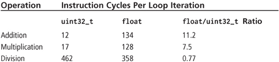
The message to be gleaned from the numbers in Table 7.4 is that you should be cognizant of the execution time differences between different arithmetic operators of the same data type and between different data types (such as integer versus floating-point) for the same arithmetic operation for a target microcontroller and compiler.
BCD Arithmetic
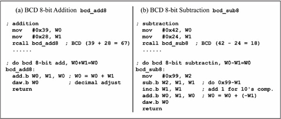
Binary coded decimal (BCD) encodes each digit of a decimal number as its 4-bit binary value. This means that the decimal value 83 is simply 0x83 as an 8-bit BCD number. Thus, an 8-bit BCD number can represent the number range 0 to 99. This is a less efficient coding scheme than binary representation, as the codes 0x9A to 0xFF and 0x?A through 0x?F are unused. Some rotary encoders that track the movement of a rotary shaft as it turns either clockwise or counterclockwise use BCD outputs. Some rotary encoders output incremental codes that only describe the direction of shaft movement; others output absolute position information. If absolute position information is given in BCD, then BCD subtraction must be performed to compute the distance between two absolute positions. Addition must be done to compute a finishing location given a starting location and a distance to travel. Adding the two numbers using binary arithmetic then post-correcting the sum to obtain the BCD value performs BCD addition. A BCD digit is a 4-bit value. When two BCD digits are added using binary addition, if the result digit is greater than 9 or if a carry is produced, the result digit must be decimal adjusted by adding 6 to produce the correct BCD digit. Similarly, when two BCD digits are subtracted using binary subtraction, if the result digit is greater than 9 or if a borrow is produced, the result digit must be decimal adjusted by subtracting 6 to produce the correct digit. The DC (decimal carry) flag in the STATUS register is used for BCD post-correction after addition operations; the DC flag is set if there is a carry from bit 3 to bit 4 during a binary addition. The daw.b Wn (decimal adjust Wn) instruction post-corrects the Wn register contents to the correct BCD value after any addition or increment instruction that affects the C and DC flags. The daw.b instruction operates only in byte mode using register direct addressing, and so the .b extension must be included. The daw.b instruction adds 6 to the lower 4 bits (lower digit) of the Wn register if the DC flag is 1 or if the lower digit is greater than 9; the upper digit is corrected by +6 if the C flag is 1 or if the upper digit is greater than 9. Unfortunately, the daw.b instruction cannot be used after a subtraction operation, so BCD subtraction requires more effort. Recall the binary subtraction A – B is performed as A + ~B + 1, where ~B + 1 is the two’s complement of B. Similarly, the BCD subtraction A – B can be performed as A + (99 – B +1), where 99 – B + 1 is the ten’s complement of B. Figure 7.13(a) shows the 8-bit BCD addition 0x39 + 0x28. After the binary addition, DCflag = 1 and the result is 0x61. Because DCflag = 1, the lower digit must be corrected by adding 6 to reach the correct result of 0x67. Figure 7.13(b) shows the BCD subtraction 0x42 – 0x24 using binary subtraction, which produces the value 0x1E and a borrow from the upper 4 bits. Because there was a borrow from the upper 4 bits, the lower digit must be post-corrected by subtracting 6 to produce the correct result of 0x18. Figure 7.13(c) shows the BCD subtraction 0x42 – 0x24 performed by adding the ten’s complement, 0x42 + (0x99 – 0x24 + 1). The ten’s complement of 0x24 is computed as 0x99 – 0x24 + 1 = 0x76. Observe that 0x24 + 0x76 = 0x00 in BCD arithmetic, or (+n) + (–n) = 0. The ten’s complement of 0x24 is then added to 0x42, or 0x42 + 0x76 = 0xB8. This sets Cflag = 1, so the upper digit is post-corrected by adding 6, producing the correct result of 0x18. Observe that Figures 7.13(b) and 7.13(c) produce the same result, but the method in Figure 7.13(c) is used on the PIC24 μC as this allows use of the daw.b instruction.
Figure 7.13
BCD addition and subtraction
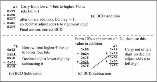
Figure 7.14(a) shows assembly code for a subroutine named bcd_add8 that performs the 8-bit BCD addition of W0 = W0 + W1bcd_add8 subroutine is called using the numbers from Figure 7.13(a). Similarly, Figure 7.14(b) shows assembly code for a subroutine named bcd_sub8 that performs the 8-bit BCD subtraction W0 = W0 - W1addc instruction forms.
Sample Question: What does 0x56 + 0x29 produce as a BCD sum?
Answer: Using binary addition, 0x56 + 0x29 = 0x7F. Post-correcting for BCD produces 0x7F + 0x06 = 0x85. So, as a BCD sum, 0x56 + 0x29 = 0x85.
Figure 7.14
Assembly code for BCD 8-bit addition and subtraction
ASCII Data Conversion
A common task in microprocessor programs is to convert numerical data in ASCII format to binary or vice versa. This functionality is generally provided by formatted IO functions in high-level languages, such as the printf (ASCII output) and scanf (ASCII input) C library functions. While the amount of ASCII data manipulation required in typical microcontroller applications is limited, the need for ASCII numerical manipulation invariably arises and one should have some familiarity with the problem.
Binary to ASCII-Hex
Suppose you wanted to see the bytes of a single or double precision floating-point number printed in ASCII format. The code in Figure 7.15 prints the individual bytes of a single precision and double precision floating-point number in ASCII-hex format. The C function byte2aschex() is the key piece of code in this discussion, as it converts a byte value into the ASCII-hex representation of that number. For example, the 8-bit value 0xA3 is converted to the two ASCII values 0x41, 0x33, as these are the ASCII codes for the two hex digits A and 3, respectively. The byte2aschex() function is called for each byte of the single precision and double precision floating-point numbers f and d, respectively. The generic pointer variable pu8_byte is used to iterate over the bytes of the floatingpoint numbers from most significant to least significant, which are assumed to be stored in little-endian order in memory (recall from Chapter 3 that little-endian means that bytes of a multibyte value are stored from least significant to most significant byte in increasing memory addresses).
The uint8_t au8_buf[2] array is used as temporary storage for the two ASCII characters generated by byte2aschex(). The byte2aschex() function converts each 4-bit portion (a nybble) of the u8_c input parameter by calling the nyb2aschex() function twice; first for the upper 4 bits, then for the lower 4 bits. Each 4-bit portion of u8_c represents one ASCII-hex digit, so an 8-bit number requires two bytes when converted to ASCII-hex. The nyb2aschex() function first tests its 4-bit input and if it is greater or equal to 10, then it is converted to its ASCII equivalent A (0x41) through F (0x46) by adding the value 0x37. If it is less than 10, 0x30 is added to the 4-bit value to produce the appropriate ASCII digit 0 (0x30) through 9 (0x39). The return value from the nyb2aschex() function is stored by the byte2aschex() function into the buffer pointed to by the pu8_s input parameter. In C, an integer can be printed in ASCII-hex format using the %x format in the printf() standard IO library function. An example usage is printf(“u8_c = %x”,u8_c), which prints u8_c = 3A if the binary value of u8_c is 0x3A.
Figure 7.15
C code for ASCII-hex display of floating-point numbers

Assembly language for the byte2aschex() and nyb2aschex() functions along with a test program is shown in Figure 7.16. The byte2aschex() assembly language implementation uses W0 for u8_c and W1 for the pu8_s pointer to the buffer used for storing the two ASCII-hex digits. The nyb2aschex()assembly language implementation uses W0 as the 4-bit input value to be converted, and returns the equivalent ASCII-hex digit in W0. The test program calls byte2aschex() with 0x9A as the value to be converted in W0, and the starting address of au8_buf in W1. Upon return, the values 0x39 (ASCII 9) and 0x41 (ASCII A) are stored at buffer locations au8_buf[0] and au8_buf[1], respectively.
Figure 7.16
Assembly code implementation of the byte2aschex() function

Binary to ASCII-Decimal
Table 7.5 shows the steps necessary to convert a binary number to its unsigned ASCII-decimal representation. The successive division by 10 produces the digits from least significant digit to most significant digit. The C statement printf(“%d”, i) prints the value of the i variable in decimal; the printf() C library function implements the algorithm of Table 7.5 when formatting numbers in ASCII-decimal format.
Table 7.5: Conversion of a Binary Number to Unsigned ASCII-Decimal
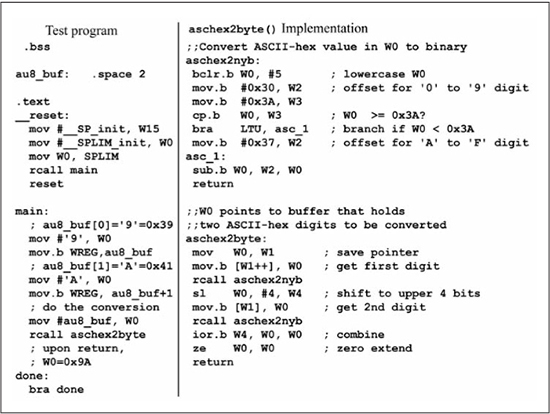
ASCII-Hex to Binary
The aschex2byte() C function of Figure 7.17 does the reverse of the byte2aschex() C function, in that it converts two ASCII characters representing the hex value of an 8-bit number into the binary value of that number. The main() code of Figure 7.17 passes a uint8_t buffer containing two ASCII-hex digits to the aschex2byte() function and saves the return value in u8_c. The aschex2byte() result is checked using the C formatted input function sscanf() in the statement sscanf(buf, “%x”, &u16_i). The %x format causes the null-terminated string in u8_buf to be scanned for an ASCII-hex value, which is converted to binary and returned in the uint16_t variable u16_i. A failure message is printed if the result returned by aschex2byte() does not match the result returned by sscanf(). The aschex2byte() function calls the aschex2nyb() function for each ASCII-hex digit to be converted. The aschex2nyb() function first converts the character to uppercase, which does not change the characters value if it is a 0 – 9 hex digit. Then it compares the ASCII value to 0x3A; if greater than 0x3A, the character must be in the range A (0x41) to F (0x46), so the value 0x37 is subtracted to get the binary value. If the character is less than 0x3A, it must be in the range 0 (0x30) to 9 (0x39), so the value 0x30 is subtracted from the character to obtain the binary value. The resulting 4-bit value from the first call to aschex2nyb() is placed by aschex2byte() in the upper half of the uint8_t variable u8_c. The 4-bit value from the second call to aschex2nyb() is combined with the 4 bits already in the upper half of u8_c by a bitwise OR (|) operation. The resulting u8_c variable is returned as the converted 8-bit binary value.
Figure 7.17
C code for converting ASCII-hex to binary

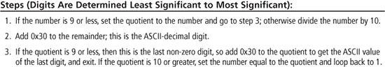
Assembly language implementations of the aschex2byte() and aschex2nyb() functions are seen in Figure 7.18 along with a test program. The assembly language implementations are straightforward conversions of the C functions. The test program calls aschex2byte() with a pointer to a buffer that contains the ASCII-hex digits 9 and A; register W0 contains the value 0x9A on return.
Figure 7.18
Assembly code implementation of the aschex2byte() function
ASCII-Decimal to Binary
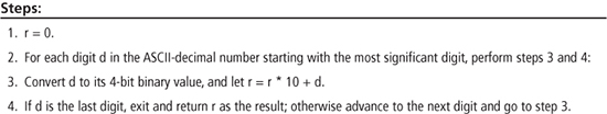
Table 7.6 shows the steps necessary to convert an ASCII-decimal number to its binary value. The conversion proceeds from most significant digit to least significant digit, converting each digit d to its binary value, and forming the sum r = r*10 + d where r is the cumulative result. The number range that can be converted is dependent upon the size of r. In C, ASCII-decimal to binary conversion can be accomplished with sscanf() using the %d format. An example is sscanf(buf, “%d”, &i16_i), which converts the first ASCII-decimal string found in buf to binary, and returns the result in i16_i.
Table 7.6: Conversion of an ASCII-Decimal Number to Binary
Summary
Multiplication operations in the PIC24 are enhanced by the availability of a 16 x 16 array multiplier, which can be used to implement higher-precision multiplications. Hardware support for division exists in the PIC24 instruction set for 32-bit/16-bit and 16-bit/16-bit operands, and requires a repeat #17 instruction to iteratively produce each bit of the quotient. Saturating arithmetic is a method for dealing with overflow in addition and subtraction by clipping the result to either the maximum or minimum values of the number range in case of overflow or underflow, respectively. Floating-point representation encodes an exponent field in addition to magnitude and sign information, greatly expanding the number range that can be represented, at the cost of extra complexity in performing floating-point calculations. Binary coded decimal (BCD) encodes each decimal digit as a 4-bit value, providing fast conversion from BCD to decimal, and vice versa. Support for BCD arithmetic is present in the PIC24 via the DC flag and the daw.b instruction. Conversion of ASCII numerical data in hex or decimal formats to binary, and vice versa, is required for input/output operations of ASCII numerical data and is usually implemented in the form of formatted IO subroutines.
Review Problems
For problems 1 through 18, give the affected registers after execution of each instruction. Indicate if overflow occurs for division instructions. Assume the register and memory contents of Table 7.7 at the beginning of each problem. Show the decimal equivalents of the operation that is performed and verify your result. Assume that the divide instructions have a repeat #17 in front of them.
Table 7.7: Register Memory Contents

1. mul.uu W0, W1, W8
2. mul.ss W0, W1, W8
3. mul.us W0, W1, W8
4. mul.su W0, W1, W8
5. mul.ss W2, W3, W8
6. mul.us W2, W3, W8
7. mul.su W2, W3, W8
8. mul.uu W2, W3, W8
9. div.u W6, W2
10. div.s W4, W5
11. div.u W4, W5
12. div.s W4, W2
13. div.ud W8, W4
14. div.sd W8, W4
15. div.sd W6, W8
16. div.ud W8, W6
17. div.s W6, W9
18. div.ud W6, W4
19. What is the value 0xC4 as a 0.8 unsigned fixed-point number?
20. What is the value 0xC4 as a 4.4 unsigned fixed-point number?
21. What is the value 0xC4 as a 1.7 signed fixed-point number?
22. What is the value 0xC4 as a 3.5 signed fixed-point number?
23. Convert 23.33 to 5.3 unsigned fixed-point number.
24. Convert 0.2325 to 0.8 unsigned fixed-point number.
25. Convert –0.2325 to 1.7 signed fixed-point number.
26. Convert –2.458 to 4.4 signed fixed-point number.
27. Saturating signed addition is defined as saturating to either the maximum positive value or maximum negative value in the case of overflow using two’s complement encoding. What is the result for 0x39 + 0x59 using saturating signed 8-bit addition?
28. What is the result for 0x8F + 0xE0 using saturating signed addition as defined by problem 27?
29. What is the result for 0x8F + 0xE0 using saturating unsigned 8-bit addition?
30. Write a PIC24 instruction sequence that implements signed saturating addition as defined by problem 27 assuming W0 and W1 contain the two 8-bit operands, with the saturated sum returning in W0.
31. What is the value –0.15625 in single precision floating-point format?
32. What is the value –545.6875 in single precision floating-point format?
33. The value 0x42F18000 is a single precision floating-point number; what is its decimal value?
34. The value 0xC6ED6E20 is a single precision floating-point number; what is its decimal value?
35. Write the steps of an algorithm that compares two single precision floating-point numbers a and b. Assume both numbers are normalized before the comparison is done, and that you do not have to handle special numbers. Return 1 if a > b, –1 if a < b, and 0 if a == b. Assume that you have functions named sign(), exp(), and significand() that extracts these fields and returns them as unsigned integer values. Hint: Think about comparing the numbers by comparing the individual sign, exponent, and significand fields.
36. How would you detect overflow in the BCD addition of two 8-bit numbers?
37. What is the ten’s complement of the BCD value 0x58?
38. Implement the algorithm of Table 7.6 in PIC24 assembly language for any ASCII-decimal string up to three digits (0 to 999).