CHAPTER 5
EXTENDED PRECISION AND SIGNED DATA OPERATIONS
This chapter applies the arithmetic, logical, and shift operations discussed in the previous chapter to extended-precision operands; that is, operands that are larger than 16 bits. Furthermore, signed number representation and its effect on shift and comparison operations are covered.
Learning Objectives
After reading this chapter, you will be able to:
![]() Translate C language statements that perform extended-precision addition, subtraction, bitwise logical, and shift operations into PIC24 instruction sequences.
Translate C language statements that perform extended-precision addition, subtraction, bitwise logical, and shift operations into PIC24 instruction sequences.
![]() Compare and contrast signed magnitude, one’s complement, and two’s complement representations of signed integers.
Compare and contrast signed magnitude, one’s complement, and two’s complement representations of signed integers.
![]() Translate C language statements that perform shift and comparison operations using signed operands into PIC24 instruction sequences.
Translate C language statements that perform shift and comparison operations using signed operands into PIC24 instruction sequences.
![]() Translate PIC24 branch instructions into machine code and be able to discuss the meaning of relative addressing.
Translate PIC24 branch instructions into machine code and be able to discuss the meaning of relative addressing.
Extended Precision Operations
Previous chapters have used unsigned 8-bit and 16-bit integers in C programs, which limits these variables to a 0 to 255 and 0 to 65,535 number range, respectively. Obviously, practical problems have a need to accommodate larger number ranges in C programs and PIC24 assembly language programs. The uint32_t data type originally given in Table 3.5 of Chapter 3 is a 32-bit unsigned integer data type that provides a 0 to 4,294,967,295 (232–1) number range. The need for 32-bit data types depends upon the microcontroller application, but most often they are needed when manipulating high-precision timing intervals. The lower 16 bits of a 32-bit integer is referred to in this book as the least significant word (LSW) and the upper 16 bits as the most significant word (MSW). Because the PIC24 CPU is a 16-bit CPU, operations on 32-bit data require approximately twice the number of instructions as 16-bit operations, split between manipulation of the LSW and MSW portions of the 32-bit datum. Because of the doubled execution time, program space, and data RAM required for 32-bit integers, they should only be used when the extra precision is required by the application.
32-Bit Assignment Operations
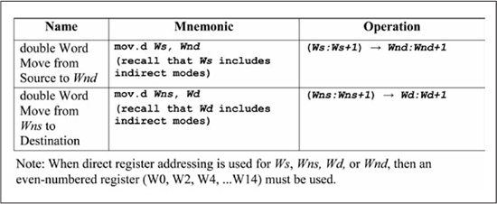
To be consistent with PIC24 technical documentation, the term double word is also used in this text in reference to 32-bit data. Figure 5.1 shows the two forms of double word moves available in the PIC24 instruction set. The first form allows register indirect modes for the source operand and thus supports copies from data RAM into the working registers. The second form supports register indirect modes for the destination operand and thus supports working register to data RAM copies. When register direct addressing (Wn) is used for either Ws, Wns, Wd, or Wnd this specifies a double word value that resides in Wn:Wn+1, with Wn referring to the LSW and Wn+1 to the MSW. Furthermore, register direct addressing is limited to even-numbered registers (i.e., W0, W2, . . .W14). When register indirect addressing is used for either Ws or Wd, any register (W0 through W15) may be used to specify the effective address of the LSW in data RAM, with the MSW address at address LSW + 2. The effective address of the LSW must be word-aligned.
Figure 5.1
Double word (32-bit) mov instructions
A double word move example that uses register direct addressing for both Wns and Wnd is shown in Figure 5.2(a). Observe that mov.d copies data from the W0, W2W0:W1W2:W3 register pair. Figure 5.2(b) illustrates a double word move from data RAM to working registers, with register indirect addressing used for Wns. The data RAM effective address for the LSW of a double word move must be word-aligned (an even address), but the register used as the source register for a register indirect addressing mode can be any working register. Observe that the destination register W2 in Figure 5.2(b) is an even-numbered register, fulfilling the requirement that a destination using register direct addressing for a double word move must be evenly numbered.
Figure 5.2
Double word (32-bit) mov examples

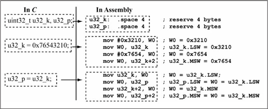
Figure 5.3 illustrates PIC24 assembly language implementation of C language variable assignment operations involving uint32_t data types. The PIC24 assembly language implementation for these particular assignments does not use any of the double word move forms, as it is more efficient in this case to simply use individual 16-bit operations on the LSW and MSW portions of the uint32_t data types. The double word move forms become more efficient for C pointer operations involving arrays of 32-bit data, which is covered in Chapter 6. In Figure 5.3, observe that the label u32_k refers to the LSW of the uint32_t u32_k variable, while u32_k+2 is used for the MSW. For C language assignment of uint32_t variables, the order in which the 16-bit assignments are made, LSW first or MSW first, does not matter as long as LSW is copied to LSW and MSW to MSW.
Figure 5.3
C language 32-bit assignment operations
32-Bit Bitwise Logical Operations
Figure 5.4 shows a bitwise AND operation applied to uint32_t operands with three assembly language implementations provided. Figure 5.4(a) uses the input/process/output approach by first copying u32_k, u32_p into the register pairs W1:W0, W3:W2. The AND operation is then performed on the LSW and MSW operands with the 32-bit result placed in the register pair W3:W2. This 32-bit result is then copied from W3:W2 to u32_k. Note that the AND instruction is applied to each 16-bit word (LSW and MSW) of the operands. It is immaterial as to the order in which a bitwise logical operation is applied to the words of a 32-bit operand, as each word operation is independent of each other, just as with the assignment operation. You might be tempted to use the mov.d instruction, as shown in Figure 5.4(b), but this is incorrect as the mov.d instruction does not support the file register addressing mode. The mov.d instruction requires use of an indirect addressing mode to access data memory and the indirect addressing modes useful for this example are discussed in Chapter 6. In this example, a mov.d approach would not save a significant number of instructions. However, Figure 5.4(c) gives an implementation that does significantly reduce the number of instructions required by using the two-operand AND instruction form. Because this approach is clearly better in terms of the required number of instructions, many of the examples in this chapter will use two-operand ALU instruction forms.
Figure 5.4
C language 32-bit bitwise logical operations

32-Bit Addition/Subtraction
Figure 5.5 shows addition and subtraction using two 32-bit operands. For the addition operation, the two least significant words are added first, followed by the addition of the two most significant words, which includes the carry (C flag) produced by the least significant word addition. The subtraction is done similarly, except the subtraction of the most significant words includes the borrow produced by the least significant word subtraction. Note that unlike logical operations, the order of the operations for addition and subtraction matter in that the LSW operation is performed first, followed by the MSW operation.
To accommodate the needs of extended precision addition and subtraction, the PIC24 instruction set includes the instructions addc (add with carry) and subb (subtract with borrow), as shown in Figure 5.6. These instructions support the same addressing modes as add/sub instructions previously discussed. There is also a cpb (compare with borrow) instruction for use in comparing extended precision operands.
Figure 5.5
Addition/subtraction with 32-bit operands
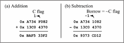
Figure 5.6
Addition/subtraction/compare instructions for extended precision operations
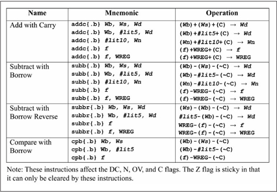
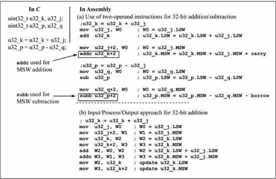
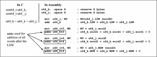
Figure 5.7 illustrates the use of addc and subb instructions for performing u32_k = u32_k + u32_j and u32_p = u32_p - u32_q, where all of the variables are of type uint32_t. Figure 5.7(a) uses two-operand add/addc instruction forms; observe that the add instruction is used for the LSW of u32_k + u32_j, followed by the addc instruction for the MSW. Similarly, the sub instruction is used for the LSW of u32_p - u32_q, followed by the subb instruction for the MSW. The no carry version of addition (add) and the no borrow version of subtract (sub) is used on the LSW because there is no carry into or borrow from the LSW. Figure 5.7(b) uses three-operand add/addc instruction forms and the input/process/output approach. Figure 5.7(b) can be modified to implement u32_p = u32_p - u32_q by replacing u32_k with u32_p, u32_j with u32_q, add with sub, and addc with subb .
Figure 5.7
Addition/subtraction using addc/subb instructions
Another difference between the add/sub and addc/subb/cpb instructions, besides the inclusion of carry/borrow, is in the manner in which the addc/subb instructions affect the Z flag. The Z flag is said to be sticky in that the addc/subb instructions can only clear the Z flag, not set it. This behavior means that in a 32-bit add/addc sequence or a sub/subb sequence, the Z flag represents the zero status of the entire 32-bit result and not just the zero status of the MSW. Figure 5.8 clarifies this by giving three 32-bit subtraction examples using sub/subb. Figure 5.8(a) shows a subtraction result whose 32-bit result is 0x0000F000, a non-zero result. After the LSW subtraction, the Z flag is 0 because the sub instruction produces a value of 0xF000. After the MSW subtraction using the subb instruction, the Z flag is still 0 even though the MSW is 0x0000 because the Z flag cannot be set by subb. Thus, the final Z flag value of 0 indicates that the 32-bit result of 0x0000F000 is non-zero. Figure 5.8(b) shows another 32-bit subtraction with a non-zero result of 0x00010000, except this time the MSW is non-zero and the LSW is zero. The Z flag is set after the LSW subtraction, but the MSW subtraction using subb produces a non-zero result, so the subb instruction clears the Z flag. The final subtraction shown in Figure 5.8(c) produces a result of 0x00000000 and a final Z flag value of 1.
The Z flag is set to a 1 by the sub instruction in the LSW operation. The Z flag remains a 1 after the MSW operation using the subb instruction because a zero result is produced, so subb leaves the Z flag at its previous value, which is a 1. This Z flag behavior means that the 32-bit equal (==) and (!=) testing can be performed using a cp/cpb instruction sequence followed by a branch on the Z flag.
Figure 5.8
Z flag behavior in addc/subb instructions
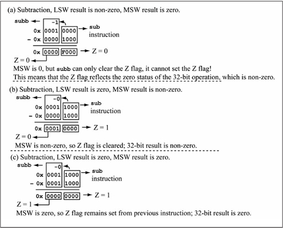
Figure 5.9 shows increment/decrement operations on 32-bit variables. Because there is no increment with carry instruction, an inc/addc sequence is used, as shown in Figure 5.9(a), where addc performs u32_k.MSW + 0 + Carry after the inc instruction increments u32_k.LSW. The W0 register is cleared first to ensure that addc u32_k+2 adds a zero to u32_k.MSW. The assembly code for decrementing a 32-bit variable in Figure 5.9(b) uses a similar approach via the dec/subb instruction sequence.
Figure 5.9
32-bit increment/decrement operations

32-Bit Logical Shift Right/Shift Left Operations
Figure 5.10(a) shows a 32-bit logical shift right operation. The MSW of u32_k is shifted first using the lsr (logical shift right) instruction, followed by the rrc (rotate right with carry) instruction on the LSW. Recall that the rrc instruction shifts the C flag into the most significant bit. Thus, the C flag is used as a 1-bit storage register for transporting the bit shifted out of the MSW into the LSW. A shift left on a 32-bit variable is shown in Figure 5.10(b). The LSW is shifted first using an sl (shift left) instruction, followed by an rlc (rotate left with carry) on the MSW with the C flag used to transport the bit shifted out of the LSW into the MSW. Figure 5.10(c) shows an implementation for the left shift of Figure 5.10(b) using the input/process/output approach. Observe that the sl/rlc instruction forms use the two-operand register-to-register forms that shift by one position, with the sl instruction affecting the C flag. You must be careful to avoid use of the three-operand forms of the sl and lsr instructions as these instructions do not affect the carry flag causing the following rlc or rrc instructions to shift in an incorrect C flag. Figure 5.10(d) shows an incorrect left shift implementation that uses the three-operand sl form.
Zero, Non-Zero Conditional Tests
A 32-bit non-zero test is shown in Figure 5.11. This is the same example used in Chapter 4 with the exception that the data type has been changed from uint16_t to uint32_t. The most straightforward method of testing a 32-bit operand for zero/non-zero is to compare the least and most significant words against 0 using cp (compare) and cpb (compare with borrow), respectively, as given in Figure 5.11(a). This works because the Z flag is sticky for cpb instruction, as previously mentioned. If the C code of Figure 5.11(a) is changed to the zero test if (!u32_k) {}, then the bra Z instruction is replaced with a bra NZ instruction to skip the if-body when u32_k is non-zero. An invalid approach for 32-bit zero test commonly tried by new assembly language programmers using the cp0 instruction is shown in Figure 5.11(b). This approach is illegal as there is no cpb0 instruction for use with the MSW comparison.
Figure 5.10
32-bit logical shift right/shift left operations

Another common implementation error is given in Figure 5.11(c), in which the zero testing approach used in Chapter 4 for 16-bit variables by copying the variable on top of itself is applied to both words of the 32-bit variable. This only tests if the MSW of the 32-bit variable is zero as the Z-bit is not sticky between the two copy operations.
Figure 5.11
Assembly language for 32-bit non-zero test

A slightly more efficient zero/non-zero test is performed on a 32-bit operand by bitwise-OR’ing the operand least significant and most significant words with each other, as shown in Figure 5.12. After the bitwise-OR, a Z = true condition indicates an operand value of zero, as the final 32-bit result can only be zero if all bits in the least significant and most significant words are zero.
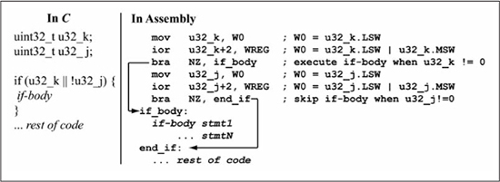
A more complex zero/non-zero test is shown in Figure 5.13, in which the if-body is executed if u32_k is non-zero or u32_j is zero (u32_k && !u32_j). Since u32_k and u32_j are being checked for their status with respect to zero, both variables are tested by the bitwise-OR of their most significant word with their least significant word. The if-body is skipped if u32_k is zero and u32_j is non-zero.
Figure 5.12
Assembly language for 32-bit non-zero test
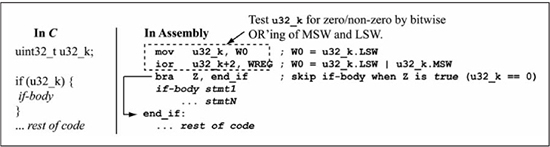
Figure 5.13
Assembly language for 32-bit zero/non-zero test with two operands
Note that the logical OR condition || in the C code in Figure 5.13 is unrelated to the bitwise-OR used in testing each variable for zero/non-zero. If the condition in the C code in Figure 5.13 is changed to (u32_k && !u32_j), in which the if-body is executed only if u32_k is non-zero and u32_j is zero, a bitwise-OR operation is still used to test the u32_k and u32_j variables for zero/non-zero. Figure 5.14 shows the C and assembly language for this test of 32-bit variables.
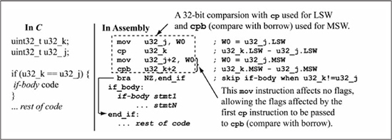
Equality, Inequality
Figure 5.15 shows assembly code for a 32-bit equality test. The if-body is executed if the test u32_k == u32_j is true. The test is performed by making a 32-bit comparison of the operands and skipping the if-body if the Z flag is cleared after the comparison, indicating that the operands are not equal. The 32-bit comparison is performed by using the cp instruction for the LSW comparison and the cpb for the MSW comparison. As previously discussed, the sticky behavior of the Z flag for the cpb instructions allows the Z flag to indicate the zero status of the entire 32-bit subtraction performed by the comparison, not just the zero status of the MSW comparison. An inequality test of u32_k != u32_j in the if condition only requires replacing bra NZ with a bra Z instruction (skip the if-body if u32_k - u32_j yields a zero result, indicating that u32_k is equal to u32_j).
Figure 5.14
Another assembly language for 32-bit zero/non-zero test with two operands
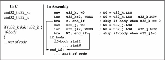
Figure 5.15
Assembly language for 32-bit equality test
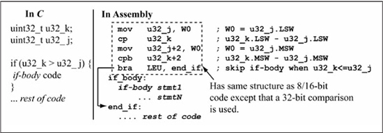
Comparisons of >, > =, <, and < = on Unsigned 32-Bit Operands
Figure 5.16 shows assembly code for a u32_k > u32_j comparison used in an if statement, where u32_k, u32_j are unsigned 32-bit operands. The only difference between this code and the 8/16-bit comparison code given in the previous chapter is that a 32-bit comparison (cp/cpb sequence) is used instead of a 16-bit comparison. It is easy to adapt any of the code examples from Chapter 4 for >, >=, <, and <= comparisons for 32-bit operands by simply using 32-bit comparisons instead of 16-bit comparisons.
Figure 5.16
Assembly language for 32-bit greater-than test
Sample Question: Implement the C code fragment shown here in PIC24 assembly.
uint32_t u32_j, u32_k;
do {
        u32_j = u32_j >> 1;
} while (u32_k >= u32_j);
Answer: One possible solution is given in Listing 5.1. The shift right of u32_j is done by using an lsr instruction for the MSW, followed by an rrc on the LSW. The comparison u32_k >= u32_j is done by a 32-bit comparison of u32_k, u32_j using cp for the LSW comparison and cpb for the MSW comparison. Finally, a bra GEU is used to return to the top of the loop as the branch is taken if u32_k >= u32_j.
Listing 5.1: Sample Question Solution
top_loop: lsr u32_j+2 ; logical shift right u32_j.MSW rrc u32_j ; right shift u32_j.LSW mov u32_j,W0cp u32_k ; u32_k.LSW - u32_j.LSW mov u32_j+2,W0cpb u32_k+2 ; u32_k.MSW - u32_j.MSW bra GEU, top_loop ; loop if u32_k >= u32_j rest of code
64-Bit Operations
A 64-bit unsigned integer is declared as unsigned long long in the C compiler used for this book, with uint64_t used as the shorthand notation that exposes the data size. Figure 5.17 shows the assembly code for a 64-bit addition of two uint64_t operands. A 64-bit variable consists of 8 bytes or four 16-bit words. Thus, four 16-bit additions are required, with the addc instruction used for all 16-bit additions after the first 16-bit addition. Because it is straightforward to extend the previously covered 32-bit operations to 64-bit operands, and because usage of 64-bit variables in 16-bit microcontroller code is rare, no further examples of 64-bit operations are given in this book.
Figure 5.17
Assembly language for 64-bit addition
Signed Number Representation
All examples up to this point have used unsigned data types. Obviously, you are also interested in performing operations on signed integers such as –100 or +27, but to do this, you must have a binary encoding method that includes the sign (+/–) of a number and its magnitude. Three binary encoding methods for signed integers are signed magnitude, one’s complement, and two’s complement. These encodings share two common features, one of which is that a positive number in any of these encodings is the same and is simply the binary representation of the number. The second common feature is that the most significant bit of a negative number is 1.
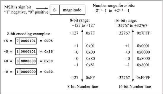
Signed Magnitude
Signed magnitude encoding is so named because the encoding is split into sign and magnitude, with the most significant bit used for the sign and the remaining bits for the magnitude. Figure 5.18 shows examples of signed magnitude encoding. With n bits, the number range is –2(n–1) – 1 to +2(n–1) – 1, or –127 to +127 for n = 8. Two encodings exist for zero, a positive zero and a negative zero. The advantage of signed magnitude is that the sign and magnitude are immediately accessible for manipulation by hardware, and it is inexpensive from a logic gate viewpoint to produce the negative of a number: simply complement the sign bit. However, one disadvantage of signed magnitude numbers is that the same binary adder logic used for unsigned numbers cannot be used for signed magnitude numbers. Signed magnitude arithmetic requires custom logic specifically designed for that encoding method. In a microprocessor, this would require special addition/subtraction instructions for use with signed magnitude integers and instructions for converting between unsigned and signed integer representations. Fortunately, as you’ll see shortly, two’s complement encoding allows the same binary adder logic to be used for both unsigned and signed representations, thus no separate instructions are needed for signed and unsigned addition/subtraction. However, there is one class of numbers, floating point numbers (i.e., –10.235), which do require their own dedicated arithmetic/logic units and instructions. Interestingly, a form of signed magnitude representation is used for floating point number encoding, which is discussed further in Chapter 7.
Figure 5.18
Signed magnitude encoding
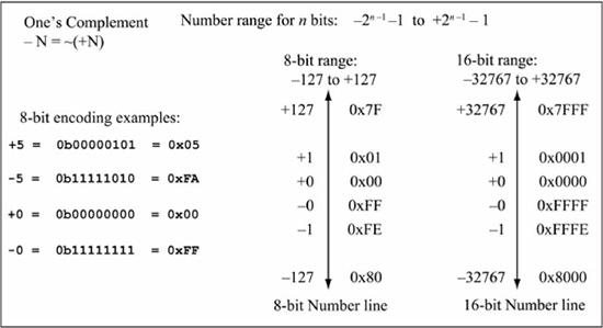
One’s Complement
One’s complement is so named because a –k is found by complementing each bit in the +k representation (i.e., –k = ~(+k)). With n bits, the number range is –2(n–1) – 1 to +2(n–1) – 1, or –127 to +127 for n = 8, the same as signed magnitude. Examples of one’s complement encodings are given in Figure 5.19. Two encodings exist for zero, positive zero (all 0s) and negative zero (all 1s). The binary adder logic used for unsigned numbers can be used for one’s complement numbers as long as an error of +1 is acceptable in the result, which occurs when you’re adding two negative numbers or a positive and a negative number. For example, the correct result for the sum +5 + (–2) is +3.
Written as 8-bit numbers in one’s complement, the sum is 0x05 + 0xFD = 0x02 (+2), which is in error by +1. The advantage of one’s complement is that the negative value of a number is “cheap and fast”—cheap in terms of logic gates and fast in terms of delay. All that is needed is an inverter for each bit, producing one gate delay for the negation operation. One’s complement has been used within some graphics hardware accelerators for color operations on pixels, where speed is all-important and an error of 1 LSb is acceptable.
Figure 5.19
One’s complement encoding
Two’s Complement
The +1 error in one’s complement addition using binary adder logic is corrected by encoding a –k as ~(+k) + 1, the one’s complement plus one. This is called two’s complement representation and is the standard method for encoding signed integers in microprocessors. With n bits, the number range is –2(n–1) to +2(n–1) – 1, or –128 to +127 for n = 8. There is only one representation for zero (digits are all 0s), with the negative zero (digits are all 1s) of one’s complement now representing a negative one (–1). The negative number range contains one more member than the positive range. Figure 5.20 gives examples of two’s complement encodings.
As stated earlier, conversion of a positive decimal number +k to two’s complement is easy, as it is simply the binary (hex) representation. The conversion of a negative decimal number to two’s complement using the formula –k = ~(+k) + 1 is error prone, as it requires the number to be converted to binary then each bit to be complemented. An easier method is to use the fact that –k = 0 – (+k), which computes –k by converting +k to hex, then subtracts that number from zero.
Figure 5.20
Two’s complement encoding
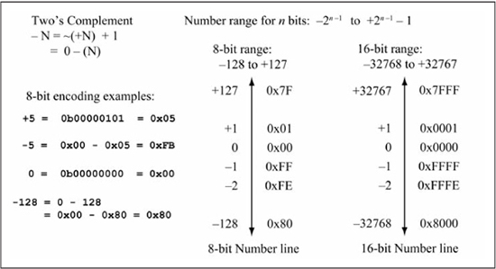
Figure 5.21(a) summarizes these rules for signed decimal to two’s complement conversion and contains two sample conversions.
Figure 5.21
Signed decimal to two’s complement and vice versa
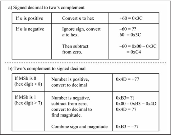
An n-bit two’s complement number can be converted to signed decimal by multiplying each binary digit by its appropriate weight, with the most significant digit having a negative weight. Thus, an 8-bit two’s complement number of the form b7b6b5b4b3b2b1b0 is converted to decimal by the sum –b7*27 + b6*26 +b5*25 +b4*24 + b3*23 + b2*22 + b1*21 + b0*20. An easier and less error-prone method is to first write the binary number as a hex number. Converting the hexadecimal two’s complement number to signed decimal requires determination of the sign and the magnitude. If the most significant bit is one (most significant hex digit is 8 or greater), the number is negative. To find the magnitude of this negative number, subtract the number from zero, as +k = 0 – (–k), and convert the result to decimal. If the most significant bit is zero (hex digit is 7 or less), the number is positive, and converting it to decimal provides +k. Figure 5.21(b) summarizes these rules and shows two examples of two’s complement hex to signed decimal conversion.
Sign Extension
To convert, or promote, an 8-bit unsigned number to a 16-bit unsigned value, one simply adds extra zeros to the leftmost digits. As an example, the unsigned decimal number 128 in 8 bits is 0b10000000, or 0x80. In 16 bits, the same number is 0b0000000010000000, or 0x0080. For two’s complement numbers, extra precision is gained by sign extension, which means the sign bit is replicated to produce the additional bits. Using the same example, the signed decimal number of –128 in 8 bits, two’s complement is 0b10000000, or 0x80. In 16 bits, the same number is 0b1111111110000000, or 0xFF80. Note that if zeros are used for padding instead of the sign bit, a negative number is changed to a positive number, an obviously incorrect result. For hex representation, extending the sign bit means padding with F digits for negative numbers, and 0 digits for positive numbers. The ze (zero extension) PIC24 instruction performs zero extension, while the se (sign extension) instruction performs sign extension. Code examples using the ze and se instructions are provided later in this chapter.
Sample Question: Give the value of –3 as a 16-bit two’s complement number.
Answer: The easiest way to accomplish this is to first write –3 as an 8-bit two’s complement number then sign extend. You know that +3 = 0x03, so –3 = 0 – (+3) = 0x00 – 0x03 = 0xFD. Sign extending (adding 1s in binary or 0xF digits in hex to the left) the 8-bit value 0xFD to a 16-bit value produces 0xFFFD. You can verify that this is correct by computing 0 – (–3) = +3, so 0x0000 – 0xFFFD = 0x0003 = +3.
Sample Question: The 8-bit value 0xA0 is a two’s complement number; give its decimal value.
Answer: The MSb of 0xA0 is a 1, so this number is negative. You know that 0 – (–N) = +N, so 0x00 – 0xA0 = 0x60 = +96. Thus, the magnitude of the number is 96 and the sign is negative, so 0xA0 = –96.
Two’s Complement Overflow
In Chapter 1, you saw that a carry-out of the most significant bit is an indication of overflow for unsigned numbers. Now you are probably wondering how overflow is detected for addition/subtraction of two’s complement numbers. First, let’s consider the sum (–1 + (+1)) written as 8-bit, two’s complement numbers, which is 0xFF + 0x01. The addition produces a carry-out of the most significant bit and an 8-bit result of 0x00 (0), the correct result for the sum –1 + (+1). This means that the carry flag is not useful as an overflow indicator for signed arithmetic. Instead, the two’s complement overflow flag (OV), bit 2 of the STATUS register, is the error indicator for two’s complement arithmetic. In this book, the OV flag is shortened to the V flag and is referred to as the overflow flag, with two’s complement understood. The STATUS register provides another useful flag for dealing with signed numbers: the negative (N) flag. This bit is set equal to the MSb of the operation result; thus, the condition N = 1 indicates a negative result if the result is interpreted as a two’s complement number.
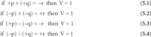
Once again, look at the ranges of positive and negative numbers in two’s complement in Figure 5.20. Note that overflow cannot occur when computing the sum of a positive and negative number. However, a two’s complement overflow can occur when the sum of two negative numbers yields a positive number, or when the sum of two positive numbers yields a negative number. Similar rules can be derived for subtraction. These rules are summarized in Equations 5.1 through 5.4. Observe that the subtraction rules 5.3 and 5.4 are simply the addition rules 5.1 and 5.2 stated in a different form:
The preceding rules aid the determination of the V flag when performing addition or subtraction manually. A method more suitable for logic gate implementation is shown by the Boolean test of Equation 5.5, where CMSb is the carry-out of the most significant bit, CMSb–1 is the carry-out of the preceding bit as produced during binary addition, and ^ is the XOR operation.
Equation 5.5 works because if two positive numbers are added (most significant bits are both 0) and CMSb–1 = 1, then CMSb must be 0 leaving behind a MSb of 1, indicating that a negative number has been produced which is overflow (for the sum of two positive numbers, the case of CMSb–1 = 0 and CMSb = 1 cannot occur). If two negative numbers are added (most significant bits are both 1), and CMSb–1 = 0, then CMSb must be 1 leaving behind a MSb of 0, indicating that a positive number has been produced which is overflow (for the sum of two negative numbers, the case of CMSb–1 = 1 and CMSb = 0 cannot occur).
Figure 5.22 illustrates the four possible cases of C, V flag settings for 8-bit addition. The operands and results are shown interpreted as both unsigned numbers and signed numbers. Observe that C = 0 if the unsigned result is correct. Similarly, V = 0 if the signed result is correct. A natural question is “How do I know if the hex numbers in Figure 5.22 are supposed to represent signed or unsigned values?” The answer is, of course, that you do not know unless you are provided with additional information. There is nothing inherent in the 8-bit code 0xFF that says it represents 255 or –1; the application that uses the numbers determines if an unsigned or signed quantity is required. In the context of μC applications, this means that the programmer knows which representation (signed or unsigned) is intended, and therefore would know which status bits are appropriate. The binary logic performing the addition does not know if the numbers represent signed or unsigned quantities, nor does it matter. The adder logic works equally well assuming either representation.
Figure 5.22
Four cases of C, V flag settings

Sample Question: Give the V, N flag settings after the 8-bit operation 0x60 + 0x40.
Answer: 0x60 + 0x40 = 0xA0. The MSb of 0xA0 is 1, so N = 1 (result is negative). Two positive numbers added together produce a negative number, so V = 1.
Operations on Signed Data
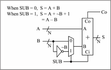
In Chapter 4, you learned in the carry flag discussion that the subtraction A – B is actually performed as A + (~B) +1, for which the reasoning is now clear as –B = ~B + 1 by the definition of two’s complement. Figure 5.23 illustrates how a combinational building block capable of both addition and subtraction is built from an adder and a 2-to-1 mux. The SUB input connected to the mux select and the carry-in input of the adder determines if the operation A + B or A – B is performed. When SUB = 0, the output is Y = A + B + 0; when SUB = 1, the output is A + (~B) + 1, which is actually A – B. An adder/subtractor building block is a key component of the arithmetic logic unit of any microprocessor. Figure 5.23 clearly shows the advantage of two’s complement representation for signed numbers; the same binary adder logic used for addition/subtraction of unsigned numbers is used for signed numbers, with the inclusion of an inverter and a 2-to-1 mux, two relatively simple logic gates.
Figure 5.23
Adder/subtractor building block
Unfortunately, some operations on signed numbers require different hardware than the same operation on unsigned numbers, and thus, different assembly language instruction sequences. Table 5.1 lists the arithmetic operations discussed in this book and whether different hardware is required for unsigned and signed operations. Shift and comparison operations on signed data are discussed in this chapter, while multiplication and division are postponed until Chapter 7.
Table 5.1: Unsigned Versus Signed Arithmetic Operations
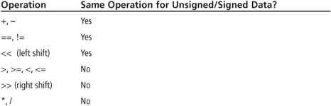
Shift Operations on Signed Data
In previous shift operation examples, a zero value has always been used as the shift-in value for the LSb (left shift) or MSb (right shift). At this point, let’s consider a shift operation on a signed (two’s complement) number. Assume a right shift of the value –128 is desired, which should yield –64 as a right shift is a divide-by-two operation (actually, this depends on the number that is shifted; more on this later). The value –128 is 0x80 as an 8-bit two’s complement number, and Figure 5.24(a) shows that this becomes a 0x40, or a +64, when a zero is used as the MSb input value. In Figure 5.24(b), the sign bit is retained during the shift, keeping the MSb as one, which produces the correct value of –64 or 0xC0. For two’s complement values, the sign bit must be retained during a right shift to obtain the correct arithmetic result of division-by-two. The PIC24 μC has an instruction named arithmetic shift right (asr) that preserves the sign bit; the asr instruction has the same addressing modes as the lsr (logical shift right) instruction discussed in Chapter 4.
Figure 5.24
Logical shift right versus arithmetic shift right

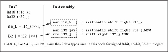
Figure 5.25 shows assembly code that implements an arithmetic shift right on 16-bit and 32-bit signed integers, which are int16_t and int32_t data types, respectively. The arithmetic right shift of the signed 16-bit variable i16_k simply uses the asr instruction instead of the lsr instruction. Arithmetic shifts of variables larger than 16 bits require that the asr instruction is used on the MSW to retain the sign bit, then the rrc instruction is used on subsequent more significant words to shift each bit right. For example, the arithmetic right shift of the signed 32-bit variable i32_j first uses the asr instruction on the MSW, followed by the rrc instruction on the LSW.
Figure 5.25
Assembly code for arithmetic shift right operation
Even though Figure 5.24(b) shows that an arithmetic right shift of –128 is –64, an arithmetic right shift of a negative number is only equivalent to division by 2 in the C language if the number is even. For odd negative numbers, division by 2 in C and arithmetic right shift produce different results. Integer division in C truncates, so –5/2 is equal to –2 as shown in the following code:
int8_t i8_k;
i8_k = – 5;        // this is 0xFB
i8_k = i8_k/2;     // returns – 2, which is 0xFE
However, the arithmetic right shift version for –5 >> 1 returns –3, as seen in the following code:
i8_k = – 5;          // this is 0xFB = 0b11111011
i8_k = i8_k >> 1;    // asr(0b11111011) = 0b11111101 = 0xFD, which is – 3!
This difference between division and right shift is not an issue for positive numbers or unsigned numbers. This is why a right shift operation in C compilers for signed numbers is implementation dependent (some retain the sign bit, some do not). When using signed numbers and dividing by powers of two, a division operation should be used instead of a right shift operation.
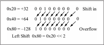
It would seem logical to assume that there is also a need for retaining the sign bit during the left shift of a two’s complement operand. Figure 5.26 illustrates what happens when the 8-bit value 0x20 (+32) is shifted to the left two times. After the first shift, the new value is 0x40 (+64), the correct value in an arithmetic sense as +64 = 2 * (+ 32). After the second shift, the new value is 0x80 (–128), which is obviously incorrect from an arithmetic sense as the sign changed. However, if the sign bit is kept during the shift, the result is 0x00, again an incorrect result in an arithmetic sense. This is because +64 * 2 = +128, and +128 cannot be represented in 8 bits! If the sign bit changes after a left shift of a two’s complement value, overflow has occurred. Keeping the sign bit does not help; it is simply not possible to represent the correct arithmetic value using the available bits. Therefore, there is no need to distinguish left shift operations based on unsigned versus signed data.
Figure 5.26
Left shift operation on signed data
Comparisons of >, >=, <, and < = on Signed Operands
Recall that the unsigned comparison tests of >, >=, <, and <= use the subtraction operation on the two operands being compared, followed by a test of the C and Z flags. Figure 5.27 illustrates what happens if two signed 8-bit operands are treated as unsigned operands for >= comparison purposes. The C flag test yields the correct result only if the signs of the operands are the same. Envision writing code to check the signs of the operands before doing the comparison, setting a temporary flag to indicate sign equality or inequality, then performing the appropriate comparison based on the flag setting. However, this is overly complex and not required, as there is a better way involving subtraction and flag tests other than the C and Z flags.
Figure 5.27
Unsigned versus signed comparisons

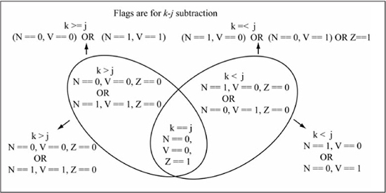
Figure 5.28 lists the V (overflow), N (Negative), Z (Zero) flag tests for >, >=, <, <= comparisons of k and j after k – j is performed. Recall the V flag is set if the operation yields two’s complement overflow, while the N flag is set if the result is negative; i.e., the result’s MSb is 1. The flag tests look complicated, but reasoning about them makes the conditions easier to remember. For the greater-than (>) test, if k is indeed greater than j, the subtraction k – j should be a non-zero (Z == 0), positive (N == 0) number, with V == 0 indicating the correctness of the result. However, if overflow occurs (V == 1), a non-zero (Z == 0), negative number (N == 1) is obtained, which is an obviously incorrect result caused by the overflow. This flag test is written in a Boolean form as (~Z&~N&~V) | (~Z&N&V). For the greater-than-or-equal (>=) test, the Z flag is dropped and the flag test simplifies to (~N&~V) | (N&V). The astute reader will recognize this flag test as ~(V^N) (the exclusive-NOR of the V and N flags), which is how this test is implemented in logic gates for signed branch instructions. The flag tests for the < and <= comparisons can be reasoned about in a similar manner.
Figure 5.28
V, N, and Z flag tests for signed comparisons
The flag tests in Figure 5.28 could be implemented by a series of branches using single flag tests on the V, N, and Z bits. Fortunately, the PIC24 instruction set has a set of signed branches that are used for signed comparisons as shown in Table 5.2. These signed branches implement the flag tests of Figure 5.28. Observe that the assembly language mnemonic for the signed branches drops the “U” suffix qualifier in the comparison; i.e., “GT” instead of “GTU”.
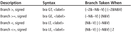
Figure 5.29 shows the assembly code when i32_k > i32_j is used as a conditional test within an if statement and i32_k, i32_j are signed 32-bit integers (int32_t). A 32-bit comparison of i32_k, i32_j is performed first, followed by a signed branch (bra LE) instruction that skips the if-body when i32_k is less than or equal to i32_j. The signed branch is used because the int32_t data type used for i32_k and i32_j is a signed 32-bit integer data type. All of the previous assembly code examples using unsigned branches and unsigned data types can be transformed into signed branches when signed data types are compared by using the proper signed version of the bra instruction.
Figure 5.29
Assembly for 32-bit signed greater-than comparison

Sign Extension for Mixed Precision
Even for operations like addition and subtraction that work the same for both unsigned and signed operands, care must be taken when dealing with operands of different precisions. The precision of the smaller operand must be extended to match the precision of the larger operand as discussed previously in Chapter 4 for unsigned data where the smaller operand was zero extended to match the precision of the larger operand. For signed operands, the smaller operand is sign extended to match the precision of the larger operand. Figure 5.30(a) shows the addition of a signed 8-bit variable (i8_i) to a signed 16-bit variable (i16_p). The i8_i variable is loaded into W0, then sign extended using the se (sign extend) instruction before being added to i16_p. The se instruction sign extends an 8-bit value in a source working register to its equivalent 16-bit value that is then placed in a destination working register.
The PIC24 instruction set does not contain a sign extend instruction for 16-bit values. One way to perform sign extension of 16 bits to 32 bits is shown in Figure 5.30(b), which adds a signed 16-bit variable (i16_i) to a signed 32-bit variable (i32_p). First, the i16_i variable is loaded into W0. Then W1 is cleared to 0 followed by a sign test of i16_i. If i16_i is negative, W1 is loaded with 0xFFFF using the setm instruction. The btsc instruction tests whether the MSb of W0, #15W0 is 0 (i16_i is greater than or equal to zero) or 1 (i16_i is negative), skipping the setm W1 instruction when i16_i is positive. Thus, the W0:W1i16_i, which is then added to i32_p.
Figure 5.30
Addition operation for signed operands of unequal precisions

Sample Question: Implement the C code fragment shown here in PIC24 assembly.
int32_t i32_j, i32_k;
do {
 i32_j = i32_j >> 1;
} while (i32_k >= i32_j);
Answer: This is the same C code as used in a sample question from earlier in the chapter, except the data type has been changed from uint32_t (unsigned) to int32_t (signed). The new solution is given in Listing 5.2, with two changes made in the assembly code from the original solution of Listing 5.1. The lsr instruction originally used for the MSW is changed to an asr instruction in order to preserve the sign bit, and the unsigned bra GEU instruction is replaced with a signed bra GE instruction.
Listing 5.2: Sample Question Solution
top_loop:
  asr i32_j+2          ; arithmetic shift right i32_j.MSW
  rrc i32_j            ; right shift i32_j.LSW
  mov i32_j,W0
  cp i32_k             ; i32_k.LSW - i32_j.LSW

  mov i32_j+2,W0
  cpb i32_k+2          ; i32_k.MSW - i32_j.MSW
  bra GE, top_loop     ; loop if i32_k >= i32_j
... rest of code
Sample Question: In the following code, what is the value of i8_i when the loop is exited? Assume that the compiler preserves the sign bit of i8_i during right shift operations.
int8_t i8_i;
i8_i = 0x80;
while (i8_i < –32) {
 i8_i = i8_i >> 1;
}
Answer: The variable i8_i is declared as an int8_t, so the assignment i8_i = 0x80 initializes i8_i to –128. Each time through the loop, i8_i is divided by 2 by the right shift assuming that the sign bit is preserved. Therefore, i8_i is –128, then –64, then –32, at which point the comparison is no longer true and the loop is exited, with i8_i = –32 (0xE0).
Branch Instruction Encoding
You have been using branch instructions for several chapters; now is a good time to take a closer look at the way these are encoded into machine code. The machine code format of branch instructions uses an addressing mode known as relative, in which a two’s complement offset is added to the program counter to determine the target branch address. The branch instruction encoding is shown in Figure 5.31, with the branch target address (BTA) computed by adding 2*#Slit16 to PCold + 2, where #Slit16 is a 16-bit signed offset and PCold is the address of the branch instruction. The PCold +2 value is used because the PC is already incremented when the branch target address computation is performed. The assembler computes the #Slit16 value from BTA and PCold as shown in Figure 5.31.
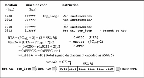
Figure 5.32 shows an example that calculates the #Slit16 value for the machine code of a branch instruction. The machine code in Figure 5.32 is representative of the code required for a loop structure like the one given in Listing 5.2. The top_loop label (0x0200) is the branch target address, while the branch location (PCold) is 0x0212. The branch displacement (#Slit16) is calculated as –10, or 0xFFF6 in 16-bit, two’s complement format. This example shows why the displacement is a signed number. A backward branch (when the branch target is at a lower memory address) requires a negative displacement, while a forward branch (when the branch target is at a higher memory address) uses a positive displacement. It is also evident that a branch target must be within the range of the displacement that can be encoded in the branch instruction word. A 16-bit displacement means that the branch target must be within –32768 to +32767 instruction words of PCold + 2. The advantage of branch instructions over a goto instruction is that a branch instruction only takes one instruction word, while a goto takes two instruction words. The disadvantage of a branch instruction is its limited range; a goto instruction can jump anywhere in program memory. Fortunately, a branch’s limited range is typically not a problem, as most loops tend to be much shorter than what is allowed by the 16-bit signed displacement. Program counter relative addressing is found in almost all microprocessor instruction sets.
Figure 5.31
Branch instruction encoding
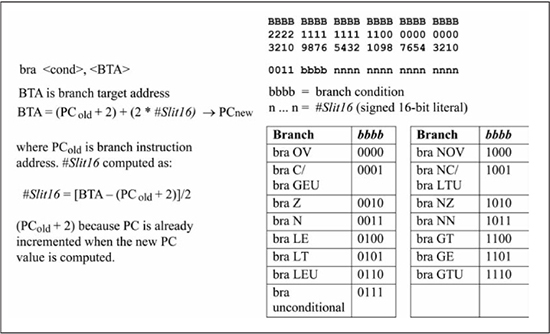
Figure 5.32
Branch instruction encoding example
Summary
Extended precision operations in the PIC24 μC allow manipulation of arbitrarily-sized data, 16 bits at a time. It is clear that variables of type uint32_t/int32_t and uint64_t/int64_t should not be used unless the extra precision offered by these data types is absolutely required by the application, as calculations on these data types require more instructions, more data RAM, and longer execution time. The standard method of signed integer representation for microprocessors is two’s complement format, which uses the same binary adder logic for addition and subtraction as used for unsigned numbers. Some operations, like right shift and >, >=, <, and <= comparisons require different instruction sequences for signed integers compared with what is used for unsigned integers. Signed branches that test combinations of the V (overflow), N (negative), and Z (zero) flags for >, >=, <, and <= are used after comparisons of two’s complement integers. The PIC24 instruction set provides explicit branch instructions to test these bits and thereby facilitates branches on signed numbers. The machine code for branch instructions uses program counter relative addressing, which means that a displacement value is added to the current PC value for determining the branch target address.
Review Problems
The answers to the odd-numbered problems can be found in Appendix C.
Convert the following C code segments to PIC24 instruction sequences. Assume that u32_i, u32_j, u32_k are all uint32_t data types and are located in near RAM. If you need to use other temporary memory locations in your solution, assume that these are located in near RAM as well.
1. Code fragment:
do {
 u32_i = u32_i – u32_k;
} while (u32_i < (u32_j + u32_k));
2. Code fragment:
if (u32_i && u32_j) {
 u32_k = u32_k & 0xCFAB0489;
}
3. Code fragment:
u32_k = u32_j | u32_i;
4. Code fragment:
while (u32_i != u32_j) {
 u32_k = u32_k >> 1;
 u32_j--;
}
Convert the following C code segments to PIC24 instruction sequences. Assume that u64_i, u64_j, and u64_k are all uint64_t data types and are located in near RAM. If you need to use other temporary memory locations in your solution, assume that these are located in near RAM as well.
5. Code fragment:
do {
 u64_i = u64_i - u64_k;
} while ( u64_i < (u64_j + u64_k) );
6. Code fragment:
if (u64_i && u64_j) {
 u64_k = u64_k & 0xFEDCBA9876543210;
}
7. Code fragment:
u64_k = u64_j | u64_i;
while (u64_i != u64_j) {
 u64_k = u64_k >> 1;
 u64_j;
}
Perform the indicated conversions:
9. The value –42 to 8-bit two’s complement.
10. The 8-bit two’s complement value 0xDC to decimal.
11. The 16-bit two’s complement value 0xFBA3 to decimal.
12. The value –390 to 16-bit two’s complement.
13. Sign extend the 8-bit value 0x85 to 16 bits.
Do the following calculations (problems 14 through 17 use 8-bit data sizes):
14. Give the value of the operation 0x73 + 0x65 and the Z, N, V, C flag settings.
15. Give the value of the operation 0x90 – 0x8A and the Z, N, V, C flag settings.
16. Give the value of the operation 0xF0 + 0xCA and the Z, N, V, C flag settings.
17. Give the value of the operation 0x2A – 0x81 and the Z, N, V, C flag settings.
18. In the following code segment, what is the value of i8_i when the loop is exited?
int8_t i8_i, i8_j;
i8_i = 0x01;
i8_j = 0x80;
while (i8_i > i8_j) {
  i8_i++;
}
19. In the following code segment, what is the final value of i8_k? Use the value 1 to represent true and 0 to represent false.
int8_t i8_i, i8_j;
i8_i = 0xA0;
i8_j = 0x70;
i8_k = (i8_i > i8_j);
20. In the following code segment, what is the final value of u8_k? Use the value 1 to represent true and 0 to represent false.
uint8_t u8_i, u8_j, u8_k;
u8_i = 0xA0;
u8_j = 0x70;
u8_k = (u8_i > u8_j);
21. In the following code segment, what is the final value of i8_i assuming that the sign bit is preserved for right shifts of signed data types?
int8_t i8_i;
i8_i = 0xA0 >> 2;
For the following problems, assume that i16_i, i16_j, i16_k are int16_t data types, i8_p, i8_q are int8_t data types, i32_r, i32_s are int32_t data types, and i64_x is an int64_t data type. All variables are located in near RAM. Convert the following C code segments to PIC24 instruction sequences.
22. Code fragment:
do {
 i16_i = i16_i - i16_k;
} while ( i16_i < (i16_j + i16_k) );
23. Code fragment:
if (i16_k >= i16_j) {
 i16_i = i16_i >> 2;
}
24. Code fragment:
i16_k = (int16_t) i8_p + (i16_j << 1) - 256;
25. Code fragment:
i16_i = ((i16_k + (int16_t) i8_q) >> 2) & 0xA34D;
26. Code fragment:
i32_r = (int32_t) i16_k + (i32_s << 1) - 1024;
27. Code fragment:
i32_r = ((i32_s - (int32_t) i8_q) >> 2) | 0x38DB807F;
28. Code fragment:
i64_x = (int64_t) i16_k + ((int64_t) i8_p << 1) - (int64_t) i32_s;
Answer the following questions:
29. What is the machine code for the instruction bra LE, 0x0300 if the address of the bra LE instruction is 0x0340?
30. What is the machine code for the instruction bra GEU, 0x0420 if the address of the bra LE instruction is 0x0404?