
APPENDIX B
CIRCUITS 001
This appendix gives a hobbyist-level introduction to basic circuits and covers the basic components (resistors, capacitors, and diodes) used in this book’s schematics.
Voltage, Current, and Resistance
Current is the flow of electrons through a conductor. A conductor is anything that allows current flow. A good conductor offers little resistance to current flow; in other words, it does not take much work for current to flow within a good conductor. In rough terms, the amount of work it takes to move electrons between two points on a conductor is voltage. The voltage difference between one end of a conductor and the other indicates the resistance of the conductor. If the voltage drop is high, the resistance is high; conversely, if the voltage drop is low, the resistance is low. A voltage supply provides a source of current at a fixed voltage level. Current is measured in amperes (A), with a few milliamperes (mA, 1 mA = 0.001 A) being the typical current requirements of the integrated circuits used in this book. Voltage is measured in volts (V) and resistance is measured in ohms (Ω). The PIC24 μC and the integrated circuits in this book require a direct current (DC) voltage supply, typically with a voltage value of +3.3 V. A DC voltage supply means that the current flows in one direction only and that the voltage is a constant value, either positive or negative. By contrast, the power available for household appliances from wall plugs is alternating current (AC), where the voltage varies in a sinusoidal fashion between ±120 V with a frequency of 60 Hz. The AC current direction reverses itself each time the voltage value crosses 0 V.
Ohm’s Law
A resistor is a component with a fixed resistance value that is used to control current flow in an electrical circuit. Figure B.1 shows a basic DC circuit consisting of a DC voltage supply and one resistor with value R.
Figure B.1
Voltage/current relationship with one resistor
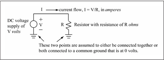
Equation B.1 gives Ohm’s Law, which expresses the current (I) flowing through the resistor as a function of voltage (V) and resistance (R).
An ideal DC voltage source supplies the current predicted by Equation B.1; thus, a resistance of zero causes infinite current flow. A zero resistance or very low resistance path is called a short, and causes large currents to flow. A physical power supply obviously cannot supply infinite current, and thus will either fail after a short period of time or blow an internal fuse, breaking the circuit path. Figure B.2 shows how a fuse is used to protect against shorts.
Figure B.2
Using a fuse to protect against shorts
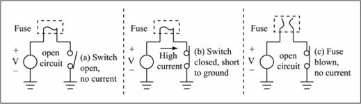
A fuse is a thin conductor that physically separates, breaking the connection, after a maximum rated current is reached. In Figure B.2(a), the switch is open so no current is flowing; in Figure B.2(b) the switch is closed, creating a short between VDD and ground; and in Figure B.2(c) the fuse has blown, creating an open path and stopping current flow.
Equation B.2 is another form of Ohm’s Law that expresses voltage across a resistor as the product of current and resistance.
Resistors in Series
Figure B.3 shows a circuit with two resistors connected in series.

In this case, the current flowing through both resistors is the same and is expressed by Equation B.3, where the total resistance of the circuit is the sum of R1 and R2.
Equations B.4 and B.5 give the voltages V1 and V2 across each resistor.
Resistors in series form a voltage divider, with the sum of voltages across the resistors equal to the voltage supply value, as shown in Equation B.6.
Voltage dividers are used in Chapter 11 to build analog-to-digital and digital-to-analog converters. Observe that if R1 = R2, V1 = V2 = Vs/2; the voltage divides equally between the two resistors.
Resistors in Parallel
Figure B.4 shows a circuit with two resistors connected in parallel.
Figure B.4
Resistors in parallel

In this case, the voltage across each resistor is the same and is equal to the power supply voltage Vs. However, the current flowing through each resistor is dependent on the resistance value, as given in Equations B.7 and B.8.
Resistors in parallel form a current divider, with the sum of the currents through the resistors equal to the total current drawn from the power supply (Is), as shown in Equation B.9.
When measuring the total current through a system like the PIC24 reference board in this book, the current draw of each individual integrated circuit can be determined by simply removing it from the board, since the current draw of each integrated circuit adds to the total current draw. Figure B.5 illustrates this concept. Observe that the integrated circuits are connected in parallel (all supplied with the same voltage).
Figure B.5
Current draw in a total system

Polarization
Most circuit elements have two terminals through which current flows. The terminals can either be polarized (have positive and negative terminals) or unpolarized. A DC power supply is polarized; it has clearly marked positive (+) and negative (–) terminals. The negative terminal is at zero volts (ground) and the positive terminal is the voltage output. A resistor is unpolarized; its operation is not affected by the direction in which its terminals are connected in a circuit.
Diodes
A diode is a two-terminal device that allows current flow in one direction only. A diode’s two terminals are named the anode and the cathode; when the voltage on the anode is approximately 0.7 V higher than the cathode voltage, current flows through the diode (the turn-on voltage for a diode varies by diode type; a Schottky diode’s turn-on voltage is approximately 0.3 V). Thus, a diode is a polarized device, as circuit operation is dependent on how its terminals are connected in a circuit. On physical diodes, the cathode terminal is identified by either a band at one end or by being the shorter of the two leads. Figure B.6 shows some simple diode circuits.

In Figure B.6(a) no current is flowing through the diode, because the anode voltage is only 0.3 V; in Figure B.6(b) current flows through the diode, as the anode voltage is greater than the cathode voltage by more than 0.7 V; in Figure B.6(c) no current is flowing, as the diode direction is reversed in the circuit; the only way for current to flow in this circuit is if Vs produces a negative voltage. The resistor is included in series with the diode in Figure B.6 simply to limit the current flow within the circuit. A diode has internal resistance but its value depends on the diode type. A light emitting diode (LED) emits visible light in proportion to the current flowing through it; the higher the current, the brighter the light.
Capacitors
A capacitor is a two-terminal device that comes in both unpolarized and polarized varieties, depending on the material that is used to make the capacitor. Polarized capacitors have clearly marked + and – terminals. Equation B.10 gives the time-dependent current flow i(t) to a capacitor as a function of capacitance (C) and the voltage rate of change (dv/dt) across the capacitor.
In intuitive terms, Equation B.10 says that if the voltage across a capacitor is not changing, then no current flows to the capacitor. Equation B.11 gives the time-dependent voltage across a capacitor as a function of capacitance and current.
In intuitive terms, Equation B.11 says that a capacitor stores charge, increasing its voltage, as current flows to it. You can think of a capacitor as a bucket that holds charge where the height of the bucket’s wall is proportional to voltage. Figure B.7 shows the effect of Equations B.10 and B.11 in an RC series circuit.
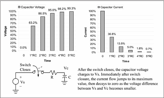
When the switch is open, the current to the capacitor and the voltage across the capacitor are both zero. At time t = 0, the switch closes and the capacitor charges up in an exponentially decaying fashion to Vs. The current jumps to its maximum value immediately after the switch closure due to the instantaneous change in voltage (maximum dv/dt), and exponentially decays to zero as the change in voltage across the capacitor (dv/dt) decreases. The Y axis is time and is marked in RC units, where the R × C product is called the time constant of the RC series circuit. The larger the time constant, the longer it takes for the capacitor to charge.
In the PIC24 reference system, the polarized capacitors used across the VDD and ground pins of the PIC24 μC are used as energy reservoirs for transient current needs caused by switching activity within the microcontroller. Physical capacitors also have some resistance associated with them called the equivalent series resistance (ESR); this needs to be low in order for the capacitors to adequately meet these transient switching needs. Ceramic and some tantalum capacitor types have low ESR values. Polarized “can”-type capacitors are aluminum electrolytic, are available in large capacitance values, and are used to provide a large charge reservoir for stabilizing the DC power supply but do not have a low ESR.
A comprehensive description of the physical characteristics of a capacitor is beyond the scope of this appendix, but it must be pointed out that current (charge) does not flow through a capacitor in the same way as current flows through a resistor. A capacitor is made from two parallel plates with a dielectric material between the plates. The plates (terminals) are isolated, and current does not pass between the plates. The dielectric material, the surface area of the plates, and the plate separation all determine the capacitance value. Charge collects on one of the plates, forming a voltage across the plates. Discharging or charging a capacitor as shown in Figure B.7 means to remove charge from or place charge on the capacitor via current flow, which changes the capacitor’s voltage.