
CHAPTER 6
POINTERS AND SUBROUTINES
This chapter examines the architectural features of the PIC24 μC that support pointers and subroutines, which are important capabilities of high-level programming languages.
Learning Objectives
After reading this chapter, you will be able to:
![]() Discuss the implementation of pointers in the C programming language.
Discuss the implementation of pointers in the C programming language.
![]() Use the indexed addressing modes of the PIC24 μC to implement C pointer operations.
Use the indexed addressing modes of the PIC24 μC to implement C pointer operations.
![]() Translate C code with array indexing into PIC24 instruction sequences.
Translate C code with array indexing into PIC24 instruction sequences.
![]() Discuss the operation of a stack data structure and its role in implementing a subroutine call and return.
Discuss the operation of a stack data structure and its role in implementing a subroutine call and return.
![]() Translate C subroutines with parameter lists, local variables, and a return value into PIC24 instruction sequences using static allocation, register allocation, and stack frame policies for parameters and locals.
Translate C subroutines with parameter lists, local variables, and a return value into PIC24 instruction sequences using static allocation, register allocation, and stack frame policies for parameters and locals.
![]() Implement initialization of C global arrays in PIC24 assembly language by copying data from PIC24 program memory.
Implement initialization of C global arrays in PIC24 assembly language by copying data from PIC24 program memory.
PIC24 Indirect Addressing Modes
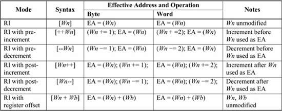
Chapter 3 introduced PIC24 indirect addressing in the context of the mov instruction. As a gentle reminder, the source operand of the instruction mov [ uses register indirect addressing, and this instruction copies the memory location content referenced by W0], W2W0 into register W2. It is not apparent in Chapter 3 how indirect addressing is useful for C code but that becomes clearer later in this chapter when C functions and pointers are discussed. However, the chapter first presents the complete set of PIC24 register indirect addressing modes, which are shown in Figure 6.1. The first addressing mode is register indirect (RI) addressing, which was discussed in Chapter 3. The next four addressing modes are register indirect with {pre/post}-{increment/decrement} and the last is register indirect with register offset.
Figure 6.1
Register indirect (RI) addressing modes
The chapter begins coverage of these addressing modes with Figure 6.2(a), which shows the instruction mov [++. The first operand in this instruction uses register indirect with pre-increment, which means that the source register used in the indirect mode is incremented before its value is used as the effective address (EA) for the operand. The register is incremented by 2 for a word operation and by 1 for a byte operation. In Figure 6.2(a), W0], W2W0’s initial value is 0x1002. Because the source operand uses pre-increment register indirect and this is a word operation, W0 is incremented by 2 prior to being used as the effective address of the source operand, giving it a new value of 0x1004. This means that the content of location 0x1004 is transferred to the W2 destination register, giving it a new value of 0xC7A6.
The only difference between Figure 6.2(a) and Figure 6.2(b) is that Figure 6.2(b) uses register indirect with post-increment, which means that the source register is incremented after its value is used as the effective address of the operand. Since W0’s initial value is 0x1002, the content of location 0x1002 is transferred to the W2 destination register, with W2’s new value being 0x4E81. The W0 register is then incremented by 2, giving it a final value of 0x1004, the same final value as in Figure 6.2(a).
Figures 6.2(c) and 6.2(d) use register indirect with pre-decrement and post-decrement operations in a mov instruction operating in byte mode. The byte mode causes W0 to be incremented or decremented by 1, instead of by 2 as in Figures 6.2(a) and 6.2(b). The same reasoning about the effective address determination for Figures 6.2(a) and 6.2(b) can be applied to Figures 6.2(c) and 6.2(d). Note that in the byte mode operations only the lower 8 bits of the destination, W2 in this case, are modified.
In summary, the register indirect with post-increment/post-decrement modes change the Wn value after it has been used as the effective address, whereas the pre-increment/pre-decrement modes change Wn before it is used as an effective address. The pre/post-increment and pre/post-decrement modes change Wn by 1 for byte operations and by 2 for word operations.
Figure 6.2
Indirect addressing mode examples

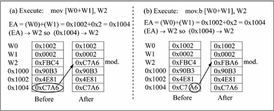
The last indirect addressing mode from Figure 6.1 is register indirect with register offset mode that computes the effective address by adding Wn and Wb; note that the Wn and Wb registers are left unchanged by this addressing mode, unlike the {pre/post}-{increment/decrement} addressing modes. Figure 6.3(a) gives an example of register indirect with register offset addressing using the mov [ instruction.W0+W1], W2
The effective address is calculated as (, or 0x1002 + 0x0002 for a final EA of 0x1004. Figure 6.3(b) uses the same addressing modes as Figure 6.3(a), except that the W0) + (W2)mov uses byte mode instead of word mode. Observe that byte mode does not change the effective address calculation. Also, unlike the pre/post increment/decrement addressing modes, the register offset addressing mode does not modify the registers used in the EA calculation, so W0 and W1 do not change in Figures 6.3(a) and 6.3(b).
Figure 6.3
Register offset addressing mode examples
Register Indirect with Signed Constant Offset
The mov instruction has an additional indirect addressing form as follows:
mov.{b}    [Ws  + slit10],  Wnd
mov.{b}    Wns,  [Wd  + slit10]
This addressing mode is not listed in Figure 6.1, as it is only valid for the mov instruction. This addressing mode is similar to the register indirect with register offset mode of Figure 6.1, except that a signed literal (slit10) replaces the register offset. For byte mode, the range of slit10 is –512 to +511, but in word mode the range is increased to –1024 to +1022 as slit10 must be even in order to maintain word alignment. This addressing mode is useful for accessing values that are a fixed offset from a base address, such as elements of C structures or values within a PIC24 stack frame (discussed later in this chapter). In Figure 6.3(a), the instruction mov [ accomplishes the same result as W0 + 2], W2mov [, given that W0 + W1], W2W1 contains a value of 2.
What Instruction Forms Support Indirect Addressing?
A common mistake for new PIC24 assembly programmers is to use invalid addressing modes for instruction operands and then be surprised when the assembler flags the error. The instruction forms given in Appendix A identify the valid addressing modes available for each operand by using special placeholder names for the operands. For example, the three-operand ADD instruction form is given as:
ADD.{B} Wb, Ws, Wd
The placeholder names Wb, Ws, and Wd are defined at the beginning of Appendix A. The Wb placeholder stands for register direct addressing, and so specifies one of W0, W1, ... W15. The Ws and Wd placeholders both represent the same set of addressing modes, which is register direct and the indirect addressing modes of [Wn], [++Wn], [Wn ++], [Wn], and [Wn--]. Using these definitions, some examples of valid and invalid forms of the three-operand ADD are:
ADD   W0, W1, W2               ; valid
ADD   [W0], W1, W2             ; invalid first operand
ADD   W0, [W1], [++W2]         ; valid
ADD   W0, W1, [W2+W3]          ; invalid third operand
Instruction Stalls Due to Data Dependencies
Chapter 3 discussed that most PIC24 instructions require one instruction word and thus one instruction cycle to execute. However, in some cases an instruction will take more than one instruction cycle for execution. For example, all change of control instructions that are one instruction word (rcall, branches) take two instruction cycles for PIC24F/H and dsPIC33F or four instruction cycles for PIC24/dsPIC33E variants to execute if the PC value is changed. This means that a conditional branch takes two or four instruction cycles if the branch is taken and one instruction cycle otherwise. The reason for this behavior is that the instruction word after the branch has already been fetched from program memory when the branch is taken. This instruction has to be discarded and a new instruction word must be fetched from the branch target address, thus requiring extra instruction cycles.
Other cases that require an extra instruction cycle are read after write (RAW) dependencies. RAW dependencies occur when a working register that is modified in the previous instruction is used as a source address for a data memory access in the current instruction (i.e., the register is used in an indirect addressing mode for a source operand). For example, the instruction sequence
(1)    add W0, W1, W2
(2)    mov [W2++], W3
generates an instruction execution stall, which requires one extra instruction cycle because W2 is modified in instruction (1) while being used as an indirect source address in (2). Because of the pipelined implementation of the PIC24 μC, instruction execution in (1) has not yet been completed (W2 has not been written) when instruction (2) starts its execution. Since instruction (2) must have the content of W2 to execute, instruction execution must stall until the value of W2 is finalized.
The following instruction sequence does not generate a stall
(3)   add W0, W1, W2
(4)   mov W2, W3
because W2, modified in (3), is not used for a data memory access in instruction (4). Instruction stalls due to branches and RAW dependencies must be included when determining accurate instruction cycle counts for time-critical assembly code. Remember that a RAW stall occurs when a working register written by an instruction is used as an address in the next instruction.
Using Subroutines
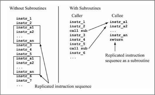
A subroutine is a block of code that is called from different locations within the main program or other subroutines. Instead of duplicating commonly used instruction sequences in multiple locations, the instruction sequence can be encapsulated as a subroutine in a single location and called when needed. Using subroutines reduces code size, as the subroutine resides in only one place in program memory instead of multiple locations. This also improves code clarity and produces code that is easier to maintain, as any code modifications are only performed in the subroutine body instead of within the duplicated code sections. Figure 6.4 illustrates this concept. The main program or other subroutine that calls a subroutine is known as the caller, whereas the subroutine being called is known as the callee.
Figure 6.4
Use of subroutines saves code space
The basic form of a C subroutine and a specific example are seen in Figure 6.5. In C, the preferred name for a subroutine is function, and these two terms are used interchangeably in this book.
The example subroutine is named countOnes(), which counts the number of bits that are equal to 1 in a 16-bit value. Subroutines have distinct components that are defined as follows (it is not necessary for a subroutine to have all of these components):
![]() Parameter list: Some subroutines are fixed sets of instructions that perform the exact same operation each time they are called. However, a subroutine can also have parameters that alter the subroutine’s behavior based on their values. The
Parameter list: Some subroutines are fixed sets of instructions that perform the exact same operation each time they are called. However, a subroutine can also have parameters that alter the subroutine’s behavior based on their values. The countOnes() subroutine in Figure 6.5 has one parameter named u16_v of type uint16_t.
![]() Local variables: A subroutine may need additional variables that are used internally to perform its function. In C, these variables are declared within the subroutine and are visible only to the subroutine itself. The
Local variables: A subroutine may need additional variables that are used internally to perform its function. In C, these variables are declared within the subroutine and are visible only to the subroutine itself. The countOnes() subroutine in Figure 6.5 has two local variables named u8_cnt and u8_i; the u8_cnt variable is used to keep track of the number of 1 bits found in the u16_v parameter while u8_i is the loop counter for the for loop.
![]() Return value: In C, a subroutine may return a single value to the caller by means of the
Return value: In C, a subroutine may return a single value to the caller by means of the return statement. The countOnes() subroutine returns a value of type uint8_t to the caller, which in this case is the local variable u8_cnt. If a C function returns no value then its return type should be declared as void. If a function does not return a value then it is not required that the subroutine contain an explicit return statement; an implicit return is done when the end of the subroutine body is reached.
Figure 6.5
C subroutine example
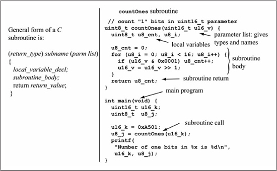
The countOnes() subroutine uses a counting loop that is executed 16 times, where the u8_cnt variable is incremented if the least significant bit of u16_v is a 1, followed by a right shift of u16_v to move the next bit of u16_v into the LSb position. The number of 1 bits in u16_v is thus counted by u8_cnt, which is returned to the caller by the statement return u8_cnt. The main() code in Figure 6.5 uses the local variable u16_k as the parameter passed to the countOnes() subroutine, which is called by the statement u8_j = countOnes(u16_k). The assignment operator of the subroutine call copies the return value of countOnes() to the local variable u8_j. The C language semantics define that subroutine parameters are passed by value to the subroutine. This means that the variable u16_k in main() is unaffected by the subroutine call; that is, u16_k retains its original value after the subroutine call because its value is copied to the memory location or register used for the subroutine parameter. The printf() statement in main() is a formatted print statement included for example purposes so that you can compile this program with a C compiler on a personal computer and observe the input parameters and return value. The printf() statement is not implemented when you translate this C code to PIC24 assembly code later in this chapter; see any C reference for more details on printf() syntax.
The Stack and Call/Return, Push/Pop
A subroutine call is a jump to the first instruction of the subroutine, while a subroutine return is a jump back to the instruction in the caller following the subroutine call. The location returned to by a subroutine return is known as the return address. Figure 6.6 shows the problem with implementing subroutine call and return by use of goto instructions. Subroutine A is called twice from within the calling program, once from label C1 and once from label C2. Labels R1 and R2 mark the return addresses. The first call (1) and return (2) to subroutine A work as intended. However, while the second call (3) also works correctly, the return (4) is incorrect, as location R1 is the return address instead of R2. Clearly, a mechanism other than a goto instruction is needed to implement call and return, as the return address depends on the call location. On the PIC24 μC, the call and rcall instructions implement subroutine call, while the return and retlw instructions implement subroutine return.
Figure 6.6
Implementing call/return with goto

What is needed is a method for saving the return address for later use by the subroutine return statement. A stack data structure is a commonly used mechanism in microprocessors for saving return addresses of subroutine calls. One way to visualize stack operation is by a stack of boxes, in which boxes are placed (stacked) sequentially on top of each other. Figure 6.7 illustrates a three-box stack in which box A is placed first, then box B, and finally box C. In this stack the top of stack (TOS) is the first free or empty location for a new item. Removing boxes from the stack is done in reverse order; first box C, then box B, and finally box A. Placing an item on the stack is referred to as a push operation, while removing an item is known as a pop operation. A stack is empty if it contains no items; a stack is full if another item cannot be pushed onto the stack. Another common name for a stack is a last-in, first-out (LIFO) buffer, as the name describes the order in which data is accessed.

The Data Memory Stack
A stack data structure requires a set of memory locations for storing the stack items and a stack pointer (SP) that contains the memory address of the current top of the stack. Most microprocessors have a special register dedicated for the stack pointer; the PIC24 μC uses working register W15 as its stack pointer. In this text, the symbol SP (stack pointer) is used interchangeably with W15 when discussing stack pointer operations. Before the stack can be used for data storage, the stack pointer must be initialized to point somewhere in data memory. Typically, the SP register is initialized to a data location that immediately follows all of the statically allocated program space. This initialization is done by C runtime code that is executed before main() is called. This is discussed in more detail later in this chapter. Figure 6.8(a) illustrates how a push operation on the PIC24 memory stack operates. The stack pointer (W15) is initialized to point to location 0x1200, which is an arbitrary choice for the purpose of this discussion. A push operation writes source data (i.e., dataA) as specified by the source addressing mode to the location pointed to by W15, then increments W15 by 2, leaving W15 with the new value of 0x1202. The PIC24 memory stack grows toward increasing memory locations as data is pushed onto the stack. Figure 6.8(b) shows that a pop operation performs the reverse operations of a push, that is, W15 is first decremented by 2, then the location pointed to by W15 is read and the data stored to a destination specified by the destination addressing mode.
Figure 6.8
Memory stack push, pop operations

After the pop operation the value of W15 is 0x1200, the same value as it was before the push operation. Note that the data read by a stack pop is still in memory, since a read is non-destructive. However, this data is now inaccessible if only push or pop operations are used to access stack data. A second pop operation cannot access the data because this decrements W15 by 2 before reading memory. Another push operation writes to location 0x1200 before incrementing W15 by 2, overwriting the previous stack data.
Figure 6.9 shows the forms of the push and pop instructions that access the data stack via W15. Observe that there are no byte mode push/pop instructions; all forms are either word or double word operations. The Wns and Wnd registers specified in double word operations must be even-numbered.
Figure 6.9push, pop instruction forms

The execution of a push W0 instruction is shown in Figure 6.10(a). After instruction execution, the memory location pointed to by W15 (0x1250) is changed to the W0 register value (0xCD18), and W15 is incremented by 2 to its new value of 0x1252. Note that a mov instruction accomplishes the same actions as W0, [W15++]push W0, so it is helpful to remember that a push operation is simply a memory write with W15 specifying the destination address via the register indirect with post-increment addressing mode. Figure 6.10(b) illustrates the execution of a pop 0x1000 instruction. Register W15 is first decremented by 2 to point at location 0x1250, and the content of 0x1250 is transferred to location 0x1000. This is semantically equivalent to a mov [W15], 0x1000 instruction, but do not try this in the PIC24 assembler because this addressing mode combination is not allowed with the mov instruction. Thus, a pop operation is a memory read operation with W15 specifying the source address via the register indirect with pre-decrement addressing mode.
Figure 6.10push, pop instruction execution example

Call/Return and the Data Memory Stack
One of the principal uses of the data memory stack is for the storage of the return address during a subroutine call, which has two instruction forms named call target and rcall target. Both instruction forms first store the return address on the data memory stack before transferring control to the target address. The difference between a call and rcall is similar to the difference between the goto and bra unconditional instructions. A call instruction takes two instruction words and can transfer control anywhere in program memory, while an rcall only takes one instruction word and uses program relative addressing (see Chapter 5) to specify the destination, thus limiting the range of the rcall instruction. Figure 6.11 shows how return addresses are stored on the data stack for a series of nested subroutine calls. The stack pointer is initialized to location 0x1200 for the example. With execution starting at main, the first subroutine call that is executed is call sub_a (1). This pushes the return address 0x000244 on the stack as two 16-bit words, which advances the stack pointer to 0x1204, after which a jump is made to sub_a. The return address for a call instruction is computed as PC + 4, where PC is the program memory address of the call instruction. Within sub_a, the call sub_b (2) instruction pushes the return address 0x00026E on the stack, advancing the stack pointer to 0x1208, then control is transferred to sub_b. The final subroutine call is made from within sub_b by the rcall sub_c instruction. Because the rcall instruction is one instruction word, the return address pushed on the stack is PC + 2, which in this case is 0x00033E, leaving the stack pointer at 0x120C. The return instruction is used at the end of a subroutine to return to the caller, which is accomplished by popping the return address from the stack and using the return address as the new PC value. The first return instruction (4) executed is in subroutine sub_c, whose execution pops 0x00033E from the stack, decrementing the stack pointer by 2 to 0x1208. Subsequent return instructions at point (5) in sub_b and point (6) in sub_a pop the return addresses 0x00026E, 0x00244 from the stack, leaving the stack pointer at its original value of 0x1200.
Figure 6.11
Storage of return address on data memory stack

Stack Overflow/Underflow
A program should execute the same number of stack pop operations as stack pushes and the same number return instructions as call instructions in order to remove the same amount of data from the stack as is placed on the stack. If this is not done, then the stack eventually underflows (the stack pointer decrements past its initial value) or overflows (the stack pointer increments past the end of implemented data memory). The stack pointer limit (SPLIM) register is a special function register that is used to automatically detect stack overflow. If a stack push is done when the stack pointer is greater than the SPLIM value then a stack error trap is generated, causing program execution to automatically jump to the stack error vector (general discussion about traps and interrupts is found in Chapter 9). Generally, the SPLIM register is initialized to a value that is a few words less than the end of data RAM (the amount of data RAM varies by device); the reasons for this are discussed further in Chapter 9 in the coverage of traps and interrupts. A stack error trap for stack pointer underflow is generated if the stack pointer is decremented below the location that is the start of data RAM (location 0x1000 for PIC24EPXXXGP devices) to prevent stack operations from occurring within the special function register space.
Implementing Subroutines in Assembly Language
The instruction forms for call/return are shown in Figure 6.12. The call Wn and rcall Wn forms allow the effective address of the subroutine to be computed from a working register value instead of a literal. As with the goto instruction, the call label_lit23 form allows the subroutine to be located anywhere in program memory at the cost of two instruction words. The other call forms are one instruction word, with rcall limited to a target subroutine that is within ± 32 Ki programs words of the current PC and call Wn limited to the lower 32 Ki instructions of program memory. Both the return and retlw instructions transfer control by popping the return address from the stack into the PC register, but the retlw instruction also places the constant #lit10 into register Wn, which is useful for subroutines that return a constant value to the caller.
Figure 6.12
Instruction forms for call and rcall

Static versus Dynamic Parameter Allocation
In translating a C function to a subroutine in PIC24 assembly language, the first decision is how to allocate the data locations or registers needed for parameters, local variables, and the return value. One method is static memory allocation, in which data memory locations are assigned to parameters and locals, and the same locations are used each time the subroutine is called. Static memory allocation is attractive in processors that have a small number of general purpose registers or lack efficient support for a data memory stack. The disadvantage of static allocation is that subroutine recursion is not allowed; that is, the subroutine cannot call itself (or call another subroutine that eventually calls the original subroutine). Subroutine recursion cannot be used with a static allocation strategy because the data locations for parameters and local variables are still in use when the subroutine is reentered by the nested call to itself. The recursive call overwrites the subroutine data memory area with new values, losing the values still in use by the first call to the subroutine. Note that any variables declared outside of a C function (global variables) are always statically allocated.
Dynamic memory allocation uses a new set of memory locations for each subroutine call, so clashes between data memory locations in recursive subroutine calls are avoided. Figure 6.13 illustrates the problem with using static allocation for recursive subroutines. In this example, the C function sub_a uses a local variable named u16_i and recursively calls itself if its input parameter u16_n has value 1. Figure 6.13(a) has the u16_i internal variable of sub_a declared locally to sub_a, causing a new memory location to be allocated for u16_i each time sub_a is called, assuming dynamic allocation.
The first invocation of sub_a executes the if-body because u16_n == 1, causing sub_a to be called a second time, this time with u16_n == 0. In the second invocation of sub_a, the if-body is skipped as u16_n is zero. The assignment u16_i = 5 in the second invocation of sub_a has no effect on the u16_i value in the first invocation, as each version of u16_i has a different memory location. Thus, the u16_i value in the first invocation of sub_a remains at 10, is incremented to 11, and then is returned to main().
Figure 6.13
Dynamic versus static allocation with recursive function calls

Figure 6.13(b) moves the declaration uint16_t u16_i out of the function, making it a statically allocated variable, causing each call to sub_a to use the same memory location for u16_i. This time, the assignment u16_i = 5 in the second invocation of sub_a overwrites the previous value 10 assigned to u16_i in the first invocation of sub_a. When a return is made to the first invocation of sub_a, u16_i has the value of 5, which is incremented to 6 and returned to main(). If static allocation is used for subroutine parameters and local variables, subroutine recursion is not allowed. Another form of recursion occurs when an active subroutine is interrupted (execution of the subroutine is halted at an arbitrary point), and the same subroutine is called by an interrupt service routine (code that is executed to handle the interrupt source), causing two copies of the subroutine local variables to be needed at the same time (interrupts and interrupt service routines are discussed further in Chapter 9). This type of recursion can be a common occurrence in microcontroller applications, and as such, dynamic memory allocation is preferred if the microcontroller can support it in an efficient manner. Some C compilers allow a choice of static versus dynamic allocation via a compiler option. One method for implementing dynamic allocation is to use the data memory stack for both subroutine parameters and local variables, which is discussed later in this chapter. Another method for implementing dynamic allocation is to use working registers for both subroutine parameters and local variables, with the data memory stack used to save current register values when new versions of the registers are required. This method is discussed further in this section and is the primary method used in this text for subroutine parameters and local variables.
Using Working Registers for Subroutine Parameters and Locals
Before examining subroutine assembly language examples, a policy must be established that specifies how working registers are used for subroutine parameters and locals. The policy used in this book is compatible with the policy used by the MPLAB® XC16 compiler, which is the compiler used for the PIC24 C code examples in Chapters 8 and higher. The working register usage policy for the assembly language subroutine examples in this book is:
![]() Registers
Registers W0-W7 are used for parameter passing, with parameters allocated to registers in left-to-right parameter order, using increasing register numbers. Registers W0-W7 are caller saved, i.e., the caller must save these registers if their values are to be preserved. An extended precision value (32-bit or 64-bit) requires multiple registers, passed in least significant to most significant word order. An 8-bit parameter occupies an entire register; two 8-bit parameters are not combined into the same 16-bit register.
![]() Function return values are returned in
Function return values are returned in W0-W3, with W0 used for 8-bit and 16-bit data, W1:W0 for 32-bit data, and W3:W2:W1:W0 for 64-bit data.
![]() Registers
Registers W8-W14 are callee saved; the subroutine must preserve these register values if they are used.
![]() Locals are allocated to any
Locals are allocated to any W0-W7 registers not used for parameters and also to W8-W14 if needed.
Figure 6.14 shows the countOnes(uint16_t u16_v) C function implemented as a subroutine in PIC24 assembly language. The u16_v parameter is passed in the W0 register, with W1 and W2 used for the u8_cnt and u8_i local variables. The return value is passed back in W0 register. The assembly code is a straightforward implementation of the C code. One small optimization is that the btst.z instruction is used to implement the least significant bit test found in the W0, #0if (u16_v & 0x0001) statement. Observe that the last instruction before the return statement is mov.b W1, W0. This copies the u8_cnt local variable implemented in W1 to the W0 register that is used for passing the return value back to the caller.
Figure 6.14
The countOnes() C function in assembly language

Figure 6.15 shows the assembly language implementation of the main() code that calls the countOnes() subroutine. Recall from Chapter 3 that the __reset label specifies the first executable instruction of the program, and that a goto __reset instruction is placed at the reset vector, which is program memory location 0x000000. The code at the __reset label is generated by the compiler, and is executed before main is called. The function of this code is to initialize the processor state and the global variable values. The __reset entry code shown in Figure 6.15 is a simplified version of what is typically generated by the MPLAB® XC16 compiler. In addition to initializing the stack pointer, the SPLIM register is initialized to the compiler generated label __SPLIM_init, which is a value that is a few words less than the end of physical memory allowing enough space for a stack trap error to be correctly handled (see Chapter 9). Also, main is called as a subroutine, followed by a reset instruction that causes the processor to undergo a reset sequence if the main function is ever returned from.
The reset sequence is discussed in more detail in Chapter 8, but it forces CPU execution to restart at program memory location zero. Placing the reset instruction after the rcall main instruction is a safety net for an unusual occurrence, as generally the main function in a microcontroller application is an infinite loop that does not return to the reset initialization code. In most compilers (including the PIC24 compiler), the code executed before main is called the crt0 module, and it contains the initialization required to launch C programs. This initialization process is explored in more detail later in this chapter.
The assembly code in main first initializes the u16_k variable to 0xA501. To prepare for the subroutine call, the u16_k variable is copied into W0 by the mov u16_k, W0 instruction since W0 is used as the u16_v parameter for the countOnes() subroutine. The rcall countOnes instruction implements the subroutine call, and the subsequent mov.b WREG, u8_j instruction copies the subroutine return value to variable u8_j.
Figure 6.15
Calling the countOnes() subroutine from main()

Saving Register Values on the Stack
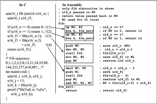
The countOnes() example is simple enough that register values do not have to be preserved during a subroutine call. For a more interesting example, consider the Fibonacci sequence of {0, 1, 1, 2, 3, 5, 8, 13, 21, 34, 55, 89, 144, ...} where each number after the first two is the sum of the previous two numbers. Figure 6.16 shows a C subroutine that computes the nth number of the sequence, where n is the subroutine input parameter. The Fibonacci calculation is most naturally performed by recursion and thus is a classic example for illustrating subroutine recursion and stack usage.
The assembly code in Figure 6.16 only shows the implementation of the fib(uint16_t u16_n) subroutine since the main() code is nearly identical to that of Figure 6.15. The assembly language implementation of the statements 1 and 2 in the fib(uint16_t u16_n) subroutine is straightforward and represents the terminal cases of the recursion, which are the points at which the subroutine does not call itself. Statement 3 is the first recursive call in the C fib() subroutine. In the assembly implementation, observe that the push W0 statement is used to save the original u16_n value on the stack in order to preserve its value when the fib(u16_n-1) subroutine call is made. After the rcall fib instruction, the return value of u16_f1 is stored in the W1 register, so popping W0 from the stack restores the original value of u16_n. The easiest method to save register values during a subroutine call is to push them onto the stack before the call, then pop them off the stack after the call. Because the subroutine call (and any other nested calls) only affects stack locations ahead of the stack pointer on subroutine entry, the stack locations used for the saved register values are undisturbed. Statement 4 is the second and last recursive call in the C fib() subroutine. The assembly language implementation saves u16_f1 (W1) on the stack before the rcall fib instruction since its value is needed after the subroutine call. The W0 (u16_n value) is not pushed on the stack for the second recursive call to fib because this value is no longer needed and can be destroyed. After the recursive call returns, W1 is popped off the stack, restoring the u16_f1 value, which is then added to the recursive call return value in W0 to form the final subroutine return value. This example illustrates the usefulness of the stack for temporary storage of variables. In general, the responsibilities of the caller in a subroutine call are to: (1) save any registers to be preserved over the subroutine call on the stack, (2) initialize parameter values, (3) call the subroutine, (4) copy any return value to a variable within the caller, and (5) pop any saved registers off the stack.
Figure 6.16
Fibonacci computation in C and assembly
The Shadow Registers
Registers W0-W3 and the status register have a set of shadow registers associated with them that allow fast save and restore of these registers. The push.s instruction copies W0-W3, and SR (C, N, V, DC, and Z flags only) to the shadow registers while the pop.s instructions copies in the reverse direction. Both instructions take only one instruction cycle, so this is faster than using separate push and pop instructions on the data stack. The shadow registers are only one deep so successive push.s instructions overwrite the contents of the shadow registers. Obviously, the usefulness of the shadow registers is dependent upon the particular subroutine. Use of the shadow registers would not have decreased instruction count or execution time of the fib subroutine in Figure 6.16.
C Pointers and Arrays
Until now, you have been using variables for unsigned and signed data of varying precisions: uint8_t/int8_t (1 byte), uint16_t/int16_t (2 bytes), and uint32_t/int32_t (4 bytes). However, another important class of variables is that of pointers, which are variables that contain memory addresses of other variables. You have already used one special function register that is actually a pointer, namely the program counter. The program counter contains the address of a location in program memory. The size of a pointer is dependent on the maximum number of locations in the referenced memory, not on the size of the data stored in the memory location. Not counting the least significant bit, which is always 0, the program counter requires 22 bits because the program memory can hold a maximum of 4 Mi instructions. Recall that an instruction is 24 bits, reinforcing the concept that a pointer’s size is independent of the size of the item that the pointer references. How wide does a pointer need to be to specify a location in the PIC24 data RAM? The answer is 16 bits, because the maximum number of separately addressable locations in the PIC24 data RAM is 64 Ki (65536), where each location stores one byte.
Pointers are most commonly used with groups of elements, such as C arrays and structures. Arrays group elements of the same type together, while structures allow grouping of different element types. C structures aren’t covered at this point, as you’ll use them only in the advanced hardware topics chapter.
Figure 6.17 shows a type declaration for a one-dimensional C array, named ai16_k, which has two elements of int16_t type. The a in the ai16_ variable name prefix is used as a reminder that this variable is an array of int16_t elements. A one-dimensional C array is declared as type array_name[asize], where asize is the array size. Array elements in C are accessed as array_name[j], where j can vary from 0 to asize–1. The array type declaration in Figure 6.17 contains some initial values for the two array elements as a convenience; arrays are like any other variable in that they may or may not be assigned initial values. Observe that the memory view of the array in Figure 6.17(a) has the array elements ordered from element 0 to element asize–1, occupying memory locations 0x1000 through 0x1002 since each array element is two bytes wide.
An int16_t pointer variable named pi16_a is also declared. The p in the pi16_ variable name prefix is used as a reminder that this variable is a pointer. The * after the type name is the dereference operator and this indicates a pointer variable type. The dereference operator can be grouped with the data type as in int16_t* pi16_a, or it can be grouped with the variable name itself, as in int16_t *pi16_a. If the first method is used, then only one variable name should be used per type declaration as any other additional variables would be the base type and not a pointer type. For example, the statement int16_t* pi16_a, pi16_b declares one pointer (pi16_a) and one int16_t variable (pi16_b), which is not a pointer in spite of the pi16_ prefix. Figure 6.17(a) shows the initial memory contents for variables ai16_k and pi16_a; the pointer variable pi16_a is shown as uninitialized even though C runtime initialization code will assign this an initial value of zero. A pointer with a zero value is said to be a NULL pointer in C.
The & (“reference” or “address of”) operator is used in the statement pi16_a = &ai16_k[1], which is read as “pi16_a is assigned the address of ai16_k[1]”. Figure 6.17(b) shows the pi16_a contents symbolically for clarity purposes after statement 1 is executed; this symbolic content is later written as a hex value after all C statements have been executed.
Statement 2, *pi16_a = *pi16_a + 1, is effectively ai16_k[1] = ai16_k[1] + 1. This is because the operation *pi16_a is read as “the value that is pointed to by pi16_a,” which is ai16_k[1] by statement 1. Thus, statement 2 modifies the contents of ai16_k[1], as shown in Figure 6.17(c).
Statement 3, pi16_a, decrements the pointer variable by one. Since pi16_a was pointing at ai16_k[1] by statement 1, it will point to ai16_k[0] after the pointer has been decremented. In hex, the value of pi16_a is the address of ai16_k[1], which is 0x1002 by Figure 6.17(a). Decrementing pi16_a by one actually subtracts two from its value in order to point to the next int16_t quantity that resides at location 0x1000. This is called pointer arithmetic, and the new value of the pointer obtained after the pi16_a operation is calculated as pi16_a - (1*sizeof(int16_t)), where the sizeof(data_type) function returns the size of the data_type in bytes. Note that if the variable pointed at an int8_t type, then it would be decremented by 1, and if it pointed at an int32_t type, then it would be decremented by 4. Thus, pointer arithmetic depends on the size of the object pointed to by the pointer.
Figure 6.17(e) gives the final hex values for the contents of the ai16_k array and the pi16_a pointer. When working through C code statements such as this example, it is best to write variable values symbolically until all statements have been executed, and then write the final hex values.
Figure 6.17
Array of int16_t data

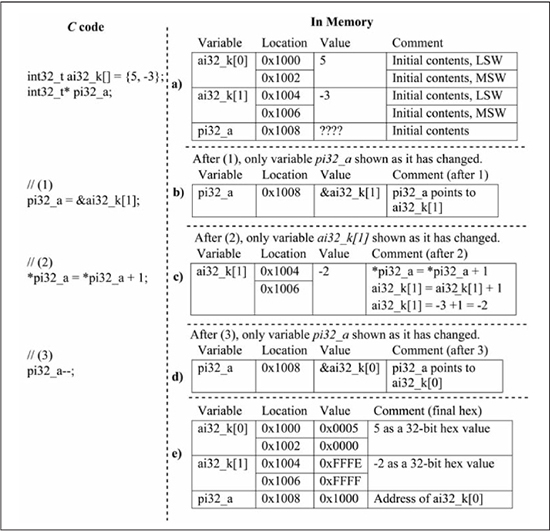
Figure 6.18 replaces the int16_t data type of Figure 6.17 with the int32_t data type. Some important observations to make when comparing Figure 6.18 with Figure 6.17 are:
![]() The symbolic contents of Figures 6.18(a-d) are the same as Figures 6.17(a-d) since only the data types have changed and not the code functionality.
The symbolic contents of Figures 6.18(a-d) are the same as Figures 6.17(a-d) since only the data types have changed and not the code functionality.
![]() The required space for the
The required space for the ai32_k array is twice that of the ai16_k array since each array element is now 32 bits instead of 16 bits.
![]() The required space for the
The required space for the pi32_a pointer variable is the same as that of the pi16_a pointer variable since all data memory pointers are 16 bits regardless of the data type that they reference.
![]() The
The pi32_a-- operation decrements the pointer value by 4 (from 0x1004 to 0x1000), since this operation is calculated as pi32_a - (1*sizeof(int32_t)), and sizeof(int32_t) is 4.
Figure 6.18
Array of int32_t data
Figures 6.17 and 6.18 illustrate two important points about array and pointer operations in C:
![]() The array access
The array access a[i] is equivalent to *(ptra + i) if ptra points to the first element of array a.
![]() The pointer arithmetic performed by
The pointer arithmetic performed by *(ptra + i) to calculate the effective address (EA) of the data access is EA = (ptra) + (i*sizeof(ptra_type)) where ptra_type is the data type that is pointed to by ptra and sizeof(ptra_type) is the width in bytes of that data type.
It is important that these two points are remembered when translating C array and pointer operations into PIC24 assembly language statements.
Implementation of C Pointer/Array Operations in Assembly
Figure 6.19(a) gives the C code for a subroutine named min that returns the minimum value in an array of type int16_t. The arguments to min are the starting address of the array (ai16_b) and the number of array elements (ui16_n). The pointer to the array is declared in array syntax by using empty brackets after the variable name. This is a third method for declaring a pointer variable in C and is simply a visual clue that this variable points to an array of elements as you can still use the dereference operator * with this variable if desired. Typically, however, if array syntax is used in the variable declaration, then array syntax is used for variable accesses. The ai16_b and ui16_n parameters are passed in registers W0 and W1 as per the previously covered parameter passing convention. The local variables i16_min and ui16_k are allocated to the W2 and W3 registers. Figure 16.19(b) shows the C code rewritten to use these register names as this is helpful when translating the C code to assembly. Observe that on line 7, the array reference ai16_b[ui16_k] is written as W0[W3*2]ai16_b requires two bytes, and so any index into this array must be multiplied by two in order to access the correct int16_t value. Figure 6.19(c) gives the assembly language implementation. This is a straight-forward translation of the C code for clarity purposes; more efficient implementations are possible. Some observations are:
![]() Assembly language lines 7-9 implement the
Assembly language lines 7-9 implement the W0[W3*2] < W2sl W3, W4 implements the multiplication by 2, and uses W4 as a temporary register. The array element is accessed by the statement mov [ on line 8, with W0 + W4], W4W4 used again as a temporary register for holding the array element. The comparison of the array element against i16_min value contained in W2 is implemented by the cp W4, W2 statement on line 9. Note that the statement cp [ may seem to be a valid optimization, but the first operand uses an invalid addressing mode for this instruction.W0 + W4], W2
![]() The subroutine return value
The subroutine return value i16_min contained in W2 is copied to W0 at line 17 before the subroutine returns, as per the policy that a function return value is passed back in register W0 for a 16-bit or 8-bit value.
Figure 6.19
A subroutine that finds the array minimum value

Figure 6.20(a) gives an alternate implementation of the min function that uses pointer notation for the parameter pi16_b that contains the starting address of the array. This is functionally the same as the ai16_b parameter used in Figure 6.19(a); there is no advantage to either declaration form. Because the array elements are accessed sequentially, the while loop in Figure 6.20 simply increments the pi16_b pointer—line 11, Figure 6.20(a)—each loop iteration instead of using array indexing. Observe that the pi16_b pointer increment is written explicitly as W0 = W0 + 2int16_t datum since an int16_t is two bytes wide. The assembly language code in Figure 6.20(c) is a straight forward translation of the C code in Figure 6.20(b). A simple optimization would be to eliminate line 12 in Figure 6.20(c) by replacing line 7 with mov [ as the post-increment indirect addressing mode increments W0++], W4W0 by 2 after the mov operation is done.
Figure 6.20
An alternative implementation for the min function

Figure 6.21(a) shows C code that calls the min function, passing it an array named ai16_x that has four elements. When an array variable name such as ai16_x is used as a parameter to a C function that expects a pointer, then the address of the array’s first element is passed to the function. If desired, the parameter can be written as &ai16_x[0] to make the value being passed to the function clearer, but it is not necessary. Figure 6.21(b) shows the assembly language implementation of the C function call. New assembly language programmers find line 1 the most confusing, which copies the starting address of ai16_x into W0. Recall that the value of an assembly language label is the memory address assigned to the label, and so #label is the address of the data memory variable as a 16-bit immediate. If the array ai16_x is located in data memory beginning at location 0x1000, then the statement mov #ai16_x, W0 represents mov #0x1000, W0. A common mistake is to write this statement as mov ai16_x, W0. This is incorrect, as it passes the value of the first array element to the function, and not the address of the first array element. Observe that line 4 in Figure 6.21(b) copies the function return value passed back in W0 to its assigned variable, which in this case is i16_m.
Figure 6.21
Calling the min function

A Subroutine That Manipulates 32-Bit Data
Figure 6.22 shows a C function named swapU32 that swaps the elements of a uint32_t array whose first element is pointed to by parameter pu32_b, with parameters u8_k and u8_j containing the array indices of the elements to be swapped. The local variable u32_s serves as temporary storage during the swap operation. In the assembly implementation, pu32_b is passed in W0 while u8_k and u8_j are passed in W1 and W2, respectively. Observe that parameters are allocated to registers W0-W7 in left-to-right parameter order, using increasing register numbers, as previously stated in the register usage policy. Registers W5 and W6 are used for the 32-bit local variable u32_s, while W3 and W4 are used to hold computed addresses for pu32_b + u8_k and pu32_b + u8_j, respectively. The computed addresses pu32_b + u8_k and pu32_b + u8_j are needed for the array accesses pu32_b[u8_k] and pu32_b[u8_j], which are *(pu32_b + u8_k) and *(pu32_b + u8_j) when written as pointer operations. I prefer the array access notation pu32_b[u8_k] over the pointer notation *(pu32_b + u8_k) for clarity reasons. The first two assembly statements in swapU32 multiply u8_k and u8_j by 4 via a shift left by two. This is needed because the address calculation of pu32_b + u8_k is done as pu32_b + (u8_k*sizeof(uint32_t)), which is pu32_b + (u8_k*4). This address computation is performed by the add instruction, where W0, W1, W3W0 contains pu32_b and W1 contains u8_k*4. A similar addition is used to compute pu32_b + u8_j.
Each assignment statement 1, 2, 3 in the C function swapU32 requires two mov instructions in the assembly code in order to copy the least significant and most significant words of the uint32_t array elements. Post-increment indirect addressing is used when addressing pu32_b[u8_k] and pu32_b[u8_j] in order to advance the address pointer from the LSW to the MSW. Post-decrement addressing is used when copying the MSW in order to restore the LSW address in the register. The assembly implementation of the C function call swapU32(&au32_x[0], 1, 3) in main() is straightforward in that &au32_x[0], 1, 3 are copied to registers W0, W1, and W2 before the rcall swapU32 instruction. The assembly code for stack pointer and stack limit register initialization is not shown.
Figure 6.22
Swapping two elements of a uint32_t array

C Strings
A common array found in C programs is a C string. The amount of string manipulation required in microcontroller programming is application dependent, but C strings are encountered often enough to warrant a basic coverage of them in this book. A C string is an array of char data where each byte is an ASCII character and the last character in the array is a 0x00 byte (also known as a null terminator or null byte). This book’s examples have not used the char data type as I have favored using either uint8_t (equivalent to unsigned char) or int8_t (equivalent to signed char) as a reminder that these are unsigned and signed 8-bit quantities. However, since C strings contain ASCII encoded characters, you should follow the normal C convention of using the char data type for C strings. One problem with using the char data type is that the default signedness (signed or unsigned) is compiler dependent. As long as comparisons are done on ASCII-encoded characters (values of 0 to 127), then signedness does not matter since unsigned and signed comparisons work the same when both numbers are positive. A zero-terminated string differs from an ordinary array of char data in that the length of the zero-terminated string may be unknown a priori. The null byte denotes the end of the string, so string routines can operate on the string’s elements one by one until it finds the null byte. Because a zero-terminated string differs so fundamentally from an ordinary char array that has a known size, you’ll use a special data prefix, sz_, to identify the string’s data type. The prefix psz_ is used to indicate a pointer to a zero-terminated string.
Figure 6.23(a) shows an example of a C string named sz_a[] that is initialized to contain “Hello” with accompanying C code that converts all of the characters in sz_a[] to uppercase. Observe that the “Hello” string contains five characters, but that the actual memory contents of Figure 6.23(b) show the array as containing six bytes since the string has an additional 0x00 byte at the end to terminate the string. The while loop in the C code executes the while-body until the character pointed to by *psz_x is equal to zero, indicating that the string end has been reached. The if statement in the while-body checks if the current character pointed to by *psz_x is a lowercase ASCII letter, that is, between the values of 0x60 and 0x7B. If the character is lowercase, then 0x20 is subtracted from it, converting the character to uppercase. The assembly code of Figure 6.23(c) is a straightforward implementation of the C code, with W0 used to implement the pointer variable *psz_x. Observe that at the end of the loop, the C statement psz_x++ is implemented by the inc W0, W0 instruction. This works in this case because psz_x++ is psz_x + (1*sizeof(uint8_t)), which is psz_x + 1.
The assembly code of Figure 6.23(c) assumes that sz_a[] resides in data memory and that the contents of sz_a[] have been initialized by code that is not shown. A section later in this chapter examines how strings such as sz_a[] are initialized before use.
Figure 6.23
A pointer example using a C string

The repeat Instruction
Figure 6.24(a) shows a C code fragment that uses a for loop to initialize the contents of a 64-element uint16_t array to zero. The assembly code implementation in Figure 6.24(b) is similar in approach to that of Figure 6.10 in that it uses W1 to point at the beginning of the array, then the loop steps through the array elements, assigning zero to each element. Register indirect with post-increment addressing is used to advance W1 to each successive array element.
Since many applications μC programs repeatedly perform the same operation as the code in Figure 6.24(b), the thoughtful designers of the PIC24 instruction set have provided a single assembly language instruction that repeats an assembly language instruction. Figure 6.24(c) shows an alternate assembly code implementation that uses the repeat instruction to accomplish the task in Figure 6.24(a).
A repeat instruction has an RCOUNT value associated with it, which is loaded into a special function register named RCOUNT when the repeat instruction is executed. The instruction following the repeat instruction is executed RCOUNT+1 number of times; this repeated execution is also referred to as the repeat loop. There are two general forms of the repeat instruction:
![]()
repeat #lit14, where #lit14 is a 14-bit literal that specifies RCOUNT.
![]()
repeat Wn, where the lower 14 bits of Wn is used as the RCOUNT value.
The RA bit in the status register is set when a repeat loop is active and is cleared when the repeat loop is finished. For this particular case, the repeat loop implementation in Figure 6.24(c) is much more efficient than the code of Figure 6.24(b) in both total number of instructions (three versus eight) and total number of instruction cycles (66 versus 388). Unfortunately, the repeat instruction can only repeat the single PIC24 assembly language instruction that follows it. This limits the repeat instruction’s usefulness for general-purpose applications. The repeat instruction is also used with the PIC24 divide instructions, which are discussed in Chapter 7.
Figure 6.24
The repeat instruction

Sample Question: For the following C code fragment, assume the variables are stored in memory starting at location 0x1000. What is the starting address of each variable assuming this code is compiled for the PIC24 μC? What is the final value of pu8_x? What array element in au8_s is modified?
uint8_t au8_s[8];
uint8_t* pu8_x;
uint8_t u8_a;
u8_a = 5;
pu8_x = au8_s;
pu8_x = pu8_x + 3;
*pu8_x = u8_a;
Answer: The starting memory location for au8_s is 0x1000. The starting memory location for pu8_x is 0x1000 + 8 = 0x1008 because au8_s occupies 8 bytes of memory. The starting memory location for u8_a is 0x1008 + 2 = 0x100A because pu8_x occupies 2 bytes of memory. (A pointer variable always occupies 2 bytes of memory regardless of the data type it references.) The pu8_x variable is first initialized to the starting address of au8_s (0x1000) as the pu8_x = au8_s assignment is equivalent to pu8_x = &au8_s[0]. The pointer arithmetic pu8_x = pu8_x + 3 is calculated as 0x1000 + (3*1) = 0x1003 since pu8_x is a uint8_t* type (a pointer to uint8_t data), so each element is 1 byte in size. Thus, the final value of pu8_x is 0x1003. The statement *pu8_x = u8_a modifies array element au8_s[3] because pu8_x is pointing to au8_s[3].
Sample Question: For the previous sample question, change the data type from uint8_t to uint16_t and answer the same questions; change uint8_t to uint32_t and answer the same questions. Assume that the variable name prefixes are also changed to reflect the new data types.
Answer: When the data type is changed from uint8_t to uint16_t, the starting memory location for au16_s is still 0x1000. The starting memory location for pu16_x is 0x1000 + 0x10 = 0x1010 because au16_s occupies 8*2 = 16 = 0x10 bytes of memory. The starting memory location for u16_a is 0x1010 + 2 = 0x1012 because pu16_x occupies 2 bytes of memory. (A pointer variable always occupies 2 bytes of memory regardless of the data type it references.) The pu16_x variable is first initialized to the starting address of au16_s (0x1000). The pointer arithmetic pu16_x = pu16_x + 3 is calculated as 0x1000 + (3*2) = 0x1006 since pu16_x is a uint16_t* (a pointer to uint16_t data), so each element is 2 bytes in size. Thus, the final value of pu16_x is 0x1006. The statement *pu16_x = u16_a modifies array element au16_s[3] because pu16_x is pointing to au16_s[3].
When the data type is changed from uint8_t to uint32_t, the starting memory location for au32_s is still 0x1000. The starting memory location for pu32_x is 0x1000 + 0x20 = 0x1020 because au32_s occupies 8*4 = 32 = 0x20 bytes of memory. The starting memory location for u32_a is 0x1020 + 2 = 0x1022 because pu32_x occupies 2 bytes of memory. (A pointer variable always occupies 2 bytes of memory regardless of the data type it references.) The pu32_x variable is first initialized to the starting address of au32_s (0x1000). The pointer arithmetic pu32_x = pu32_x + 3 is calculated as 0x1000 + (3*4) = 0x100C since pu32_x is a uint32_t* (a pointer to uint32_t data), so each element is 4 bytes in size. Thus, the final value of pu32_x is 0x100C. The statement *pu32_x = u32_a modifies array element au32_s[3] because pu32_x is pointing to au32_s[3].
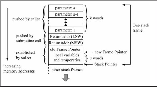
Stack Frames for Function Parameters and Local Variables
The previous section detailed a policy that uses working registers for function parameters and local variables. But what happens if the parameters and local variable storage requirements exceed the available space in the working registers? The solution is to allocate space on the stack for parameters and local variables; this set of locations is commonly referred to as a stack frame. Figure 6.25 shows the arrangement and components of a stack frame, which is compatible with the stack frame used by the MPLAB® PIC24 compiler. Because a subroutine can call other subroutines, which changes the stack pointer value, a second pointer register called a frame pointer (FP) is used as a stable reference to the parameters and local variables of a subroutine. Register W14 is used as the frame pointer in this book’s stack frames. The caller pushes the n parameters in order from n (rightmost) to 1 (leftmost) onto the stack before calling the subroutine; the number of words required for parameters depends on the number of parameters and their types. Parameters that are 8 bits wide are pushed as 16-bit values to maintain word alignment. The return address is pushed on the stack by the subroutine call/rcall instruction. The first action of the subroutine is to push the current frame pointer on the stack to preserve its value, as this subroutine changes the value of the frame pointer to reference its parameters and local variables. Local variable space is allocated by incrementing the stack pointer by the number of required words. The frame pointer is left pointing to the first local variable. Subsequent subroutine calls allocate new space above this stack frame. Parameters are accessed from the frame pointer using negative offsets, while local variables are accessed from the frame pointer using positive offsets. The subroutine return value is passed in registers according to the policy in the previous section. The subroutine must restore the frame pointer to its value on entry before executing a subroutine return. The parameters passed by the caller are also cleaned up before return, by either popping the parameters off the stack or simply subtracting the number of words required for the parameters from the stack pointer.
Figure 6.25
Stack frame components
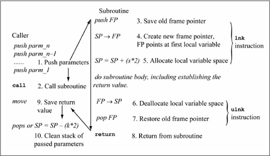
The detailed steps in constructing a stack frame are given in Figure 6.26. The majority of the work is done by the subroutine; the caller only has to push the parameters (1) on the stack before the call, save the return value, and clean the stack of passed parameters. In the subroutine, after the old frame pointer is pushed (3) on the stack, the register copy SP → FP (4) establishes the new frame pointer. This leaves the FP pointing at the first location used for local variables. Local space is allocated (5) by incrementing the stack pointer by s*2, where s is the number of words required for local variables. Actions (3), (4), and (5) are efficiently implemented by a single PIC24 instruction named lnk #lit14 (link frame pointer), which creates a new stack frame with #lit14 bytes of local storage. After the subroutine body is executed, the stack is cleaned of local variables (6) by pointing the stack pointer at the location of the old frame pointer via the register copy FP → SP. The old frame pointer is restored (7) by popping FP from the stack, after which the callee returns (8) to the caller. The ulnk (unlink frame pointer) PIC24 instruction implements actions (6) and (7). In the caller, the subroutine return value is saved (9), followed by cleaning the stack (10) of passed parameters. This is done by either popping the parameters from the stack or by decrementing the stack pointer by 2*k, where k is the number of words occupied by the parameters. The order of the events (9) and (10) is not important; (10) can be done before (9) as long as the return value is not disturbed.
Figure 6.26
Steps in constructing a stack frame
The Fibonacci subroutine from the previous section is used to illustrate assembly language implementation of stack frames. This implementation ignores the working registers for parameters and locals and uses a stack frame instead. Figure 6.27 repeats the C code for the fib() function, and shows a detailed stack frame where u16_n is accessed using a –8 offset from the FP and u16_f1 by a 0 offset. The assembly language implementation uses register indirect with register offset addressing to access values in the stack frame.
Figure 6.27
Detailed stack frame for fib() function

Figure 6.28 shows the assembly code for main() of Figure 6.27. The variable u16_j is initialized to the value 13, then u16_j is pushed on the stack before the subroutine call (rcall fib). The fib return value is returned in W0 and saved to the variable u16_k. The instruction sub W15, #2, W15 cleans the stack of the 2 bytes (1 word) of parameters passed to fib; this could have also been accomplished by popping u16_j from the stack but this destroys a register value. The numbering of the actions taken by main() corresponds to the actions found in Figure 6.26.
Figure 6.28
Assembly implementation for main() of Fibonacci example

The assembly code for the fib() subroutine is seen in Figure 6.29. The numbered actions within the subroutine code correspond to Figure 6.26. Some observations are:
![]() The
The lnk #2 instruction is used at subroutine entry to allocate the stack frame, while the ulnk instruction is used to deallocate the stack frame before returning to the caller.
![]() The parameter
The parameter u16_n is accessed from the stack frame by the instruction mov [W14 - 8], W0 (register indirect with signed constant offset) so u16_n is accessed from [FP - 8].
![]() The previous
The previous fib solution using registers saved the original u16_n value on the stack to preserve during the first recursive call. This is not needed in this solution because u16_n is already present in the stack frame; its value is reloaded after the first recursive call.
![]() The two recursive calls to
The two recursive calls to fib must also follow steps 1, 2, 9, and 10 from Figure 6.26, as these calls obviously use stack frames as well.
![]() The return value from the first recursive call is stored in the one word of local space reserved for
The return value from the first recursive call is stored in the one word of local space reserved for u16_f1 by the mov instruction, which is W0, [W14][FP + 0].
The fib implementation using a stack frame requires 19 instructions, whereas the fib implementation using registers for parameters and locals requires 15. Stack frames add extra overhead at the cost of generality for parameter passing and local storage. An optimizing C compiler will always try to use registers for parameter passing and local storage before resorting to stack frames.
Figure 6.29
Assembly implementation for fib() of Fibonacci example

Sample Question: If the swapU32 function of Figure 6.15 uses a stack frame, give the offsets from the frame pointer for parameters pu32_b, u8_k, and u8_j.
Answer: Starting from the frame pointer location, the parameters are arranged in order pu32_b (offset of –8), u8_k (offset of –10), and u8_j (offset of –12). Note that u8_k and u8_j each take a word when stored on the stack, despite being 8-bit variables. When storing 8-bit variable to the stack, you must ensure that they are properly zero-extended (unsigned) or sign-extended (signed) as required.
Program Space Visibility and Global Variable Initialization
Initial values for C global variables present an interesting challenge in microcontrollers. The C language semantics guarantee that before main() is executed, a global variable is cleared to zero if no specific initial value is given, or loaded with the initial value specified in the variable declaration. A C compiler generates initialization code that is executed on microprocessor reset before main() is called, which accomplishes global variable initialization. Figure 6.30 shows the C code of Figure 6.24 that converted a string to uppercase written as a C function named upcase(char* psz_x). The main() code calls the upcase function for two strings sz_1[], sz_2[] that have each been given initial values. Because sz_1[], sz_2[] can be modified by upcase(), these arrays must reside in data memory. However, the state of data memory is undefined at power-up, so code executed before main() is reached is responsible for initializing the contents of these two arrays. In the assembly language code, this initialization is done by a subroutine called init_variables, which is not shown in Figure 6.30.
Figure 6.30
C upcase() function and string initial values

One method for initializing global variables is for the C compiler to generate separate instructions that initialize each variable, but this is inefficient, especially for arrays. The general method that is actually used is to place the initial variable values in a tabular form in non-volatile memory, which in this case is program memory, then copy the table contents to data memory during global variable initialization. The code that does this for the MPLAB® PIC24 compiler is found in the <install_dir>xc16versionsrcpic30crt0_standard.s assembly source file. The details of the template format that specifies the variable initial contents is beyond the scope of this book. Instead, these examples use a less complex method that still illustrates the basic concepts of copying data from program memory to data memory.
Listing 6.1 shows the init_variables subroutine used to initialize the sz_1[], sz_2[] strings of Figure 6.30. The initial values for sz_1[], sz_2[] are stored in program memory at the labels sz_1_const (line 3) and sz_2_const (line 4). The .asciz assembler directive creates a null-terminated string, with the bytes packed into the lower 16 bits of each program memory 24-bit word. This is somewhat inefficient since the upper byte of each 24-bit program memory word is unused, but is necessary in this case because the assembly code uses the program space visibility (PSV) capability of the PIC24 μC to access program memory. The PSV capability on the PIC24E/dsPIC33E maps the upper 16 Ki words (32 Ki bytes) of data memory into a 16 Ki word window of program memory (the PSV window), allowing program memory to be accessed in the same way as data memory. A 10-bit special function register named the data space read page (DSRPAG) register specifies the 16 Ki program word boundary for the 16 Ki word data space mapping. The lower 8 bits of the DSRPAG register concatenated with the lower 15 bits of a working register to form a 23-bit address in program memory space. Bit 15 of the working register address must be a 1 so that the 16-bit working register address is in the range 0x8000-0xFFFF, as it is this portion of the data space that is mapped to program space (it may be simpler to think of bit 15 as a flag that must be a 1 in order to access program space). Furthermore, bits 9 and 8 of the DSRPAG register also serve as enable bits for access to the program memory space and they must be non-zero for the PSV window to be active. If DSRPAG[9:8] = 01, then a read accesses the lower 16 bits of the 24-bit program memory word, while a value of DSRPAG[9:8] = 11 accesses the upper byte of the program memory word (the earlier PIC24H family did not allow access to this byte using this mode). The DSRPAG register only allows reads of the program space. Another method for accessing program memory that allows both reads and writes of program memory words is covered in Chapter 13. The DSRPAG register also allows data space access past the normal 64 Ki byte boundary in extended data space (EDS); this usage is not discussed in this text and the interested reader should consult the data memory section of the PIC24E/dsPIC33E Family Reference Manual.
Returning to Listing 6.1, the string in program memory at location sz_1_const is to be copied to data memory. The DSRPAG register and a working register (W0 in this case) is used to form the program memory address of this string. The DSRPAG register is set by statement 7, movpag #psvpag(sz_1_const), DSRPAG. The movpag instruction is an assembly language macro that maps to a mov instruction and the operand #psvpage(sz_1_const) generates an immediate constant corresponding to the required DSRPAG value. In this particular case, the instruction generated is mov #0x200, DSRPAG with the lower 8 bits of #0x200 being 0x00 since this constant string is in the first 16 Ki words of program space. Bits 8 and 9 of the #0x200 constant are 0b01, providing access to the lower 16 bits of the program memory word. The mov #psvoffset(sz_1_const), W0 instruction (line 8) copies the lower 15 bits of the program memory address for sz_1_const to W0 and then adds 0x8000 to it in order to map it to the upper half of data memory. The mov #sz_1, W1 instruction (line 9) copies the starting data memory address for sz_1[] to W1. The copy_cstring subroutine called in line 10 copies a string whose source address is specified in W0 to the destination specified in W1. The copy_cstring implementation is straightforward; bytes are copied until a null byte is found in the source string. The null byte is copied before copy_cstring returns to the caller. Lines 13–15 initialize string sz_2[] using the contents of sz_2_const in a similar manner. Because DSRPAG is initialized prior to calling copy_cstring, all data memory reads within copy_cstring come from program memory space.
The PIC24H/dsPIC33F family also has the capability for mapping data memory into program memory, except the page register is 8 bits and is named PSVPAG (program space visibility page). The PSVPAG register allows access only to the lower 16 bits of a program memory word; the upper 8 bits cannot be accessed. Also, enabling PSV access is done through the CORCON special function register, and not from the PSVPAG register. Making Listing 6.1 compatible with PIC24H/dsPIC33F family requires adding the statement bset CORCON, #2 at the beginning of init_variables in order to enable the PSV mapping. Also, lines 7 and 12 have to be changed to modify the PSVPAG register. Line 7 must be replaced by two statements mov #psvpage(sz_1_const), W0 followed by mov . Line 12 must be modified in the same manner.W0, PSVPAG
Listing 6.1: init_variables Subroutine
(1) .bss
(2) .section .const, psv      ; constant data located in psv space
(3) sz_1_const: .asciz “Hello”
(4) sz_2_const: .asciz “UPPER/lower”
(5) .text   ; program memory
(6) init_variables:         ; copy source address (program memory)
(7)    movpag #psvpage(sz_1_const), DSRPAG   ; set page
(8)    mov  #psvoffset(sz_1_const), W0       ; place offset in W0
(9)    mov  #sz_1, W1        ; copy destination address (data memory) to W1
(10)   rcall copy_cstring
(11) ; copy source address (program memory)
(12)   movpag #psvpage(sz_2_const), DSRPAG   ;set page
(13)   mov  #psvoffset(sz_2_const), W0  ; place offset in W0
(14)   mov  #sz_2, W1        ; copy destination address (data memory) to W1
(15)   rcall copy_cstring
(16)   return

(17) ;; copy constant null-terminated string from program memory to data memory
(18) ;; DSRPAG:W0 points to program memory, W1 to data memory
(19) copy_cstring:
(20)  mov.b [W0], W2
(21)  cp.b W2, #0                  ; test for null byte
(22)  bra Z, copy_cstring_exit     ; exit if null byte
(23)  mov.b [W0++], [W1++]         ; copy byte
(24)  bra copy_cstring             ; loop to top
(25) copy_cstring_exit:
(26)  mov.b [W0++], [W1++]         ; copy null byte
(27)  return
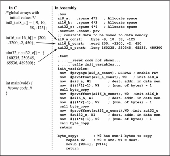
Figure 6.31 shows an example that uses a similar approach for initializing the global data arrays ai8_a[], ai16_b[], and aui32_c[] given in the C code. The assembly code stores the initial contents of these arrays in program memory at locations ai8_a_const, ai16_b_const, and aui32_c_const using assembler directives .byte, .word, and .long to initialize program memory. The init_variables subroutine calls the byte_copy subroutine three times to copy these constant arrays into data memory. The byte_copy subroutine copies W2+1 number of bytes from the source address in W0 to the destination address in W1 using a repeat instruction loop.
By default, any C global array or global scalar value is placed in data memory. However, many arrays hold constant values (values that will not change during program execution). In this case, the arrays should be located in program memory so as to free space in data memory. If a global variable is declared using the const modifier, i.e., (const uint8_t sz_1[] = “Hello”;) then the default behavior of the MPLAB® PIC24 compiler is to leave the string in program memory and to access it via the PSV window.
Summary
Pointer variables in C contain addresses that reference data. The rich set of indirect addressing modes in the PIC24 instruction set provides considerable flexibility in implementing C pointer operations. Subroutines improve code efficiency and clarity by encapsulating often-used code sequences as a single unit that can be called from multiple locations within a program. A stack is used to save the return address so a subroutine can determine the return location within the calling function. Static allocation uses a fixed set of memory locations for subroutine parameters and local variables, but does not allow subroutine recursion. The large working register set of the PIC24 μC can be used to great advantage in implementing function parameters and local variables, while also supporting recursive function calls. A stack frame is used for reserving stack space for parameters and locals when the working register space is insufficient. Global variable initial values are stored in memory to preserve them when power is off and are retrieved using a program visibility space (PSV) window by C runtime code that initializes these variables.
Figure 6.31
Initializing C global arrays
Review Problems
The answers to the odd-numbered problems can be found in Appendix C.
1. For the following code, variables are stored starting at location 0x1000. Draw memory as being 16 bits wide and show the memory locations that are assigned to each array element and variable as is done in Figures 6.1 and 6.8. Give the contents of these memory locations after all of the code is executed.
int16_t ai16_x[2];
int16_t* pi16_y;

ai16_x[0] = 5;
ai16_x[1] = -7;
pi16_y = &ai16_x[1];
*pi16_y = *pi16_y + 3;
pi16_y;
2. For the following code, variables are stored starting at location 0x1000. Draw memory as being 16 bits wide and show the memory locations that are assigned to each array element and variable as is done in Figures 6.1 and 6.8. Give the contents of these memory locations after all of the code is executed. Assume that any uninitialized variables are initialized to 0 before this code fragment is executed.
int32_t* pi32_x;
int16_t* pi16_y;
int16_t i16_b;
int32_t i32_a;
uint8_t au8_c[4];
uint8_t* pu8_w;

i16_b = -10;        // Note: value given in decimal
i32_a = i16_b >> 1;
pi32_x = &i32_a;
pi16_y = &i16_b;
pi32_x = pi32_x + 2;
pu8_w = &au8_c[3];
Assume the initial memory and register contents of Table 6.1 at the beginning of each problem, 3 through 20. Give the new register and memory contents after the instruction is executed.
Table 6.1: Register Memory Contents

3. mov [ W1], W0
4. mov W1, [W0 + W4]
5. mov.b [ W1], W0
6. mov.b W1, [W0 + W4]
7. mov W2, [W0++]
8. mov W2, [W0]
9. mov.b W2, [W0++]
10. mov.b W2, [ W1]
11. mov [W1 + W4], W2
12. mov [++W1], W1
13. mov [W1], [W0++]
14. mov.b [W1 + W4], W2
15. mov.b [++W1], W1
16. mov.b [W1], [W0++]
17. mov.b W1, [W0 + 3]
18. mov [W0 - 4], W1
19. push W1
20. pop W2
21. pop W3
22. push W0
23. lnk #6
24. ulnk
25. The instruction call 0x0400 is located at program memory location 0x020A. What return address is pushed on the stack?
26. The instruction rcall 0x0250 is located at program memory location 0x0220. What return address is pushed on the stack?
27. Implement the following subroutine in PIC24 assembly language. Use the policy established in this chapter for using working registers for subroutine parameters and locals.
// this subroutine implements a string swap.
void str_swap(char* psz_1, char* psz_2){
  char c_char;
   while (*psz_1 != 0) {
    c_char = *psz_1;
    *psz_1 = *psz_2;
    *psz_2 = c_char;
    psz_1++; psz_2++;
  }
}
28. Implement the following subroutine in PIC24 assembly language. Use the policy established in this chapter for using working registers for subroutine parameters and locals.
// this subroutine implements an uint16_t swap.
void u16_swap(uint16_t* pu16_x, uint8_t u8_i, uint8_t u8_j){
  uint16_t u16_k;

  u16_k = pu16_x[u8_i];
  pu16_x[u8_i] = pu16_x[u8_j];
  pu16_x[u8_j] = u16_k;
}
29. Implement the following subroutine in PIC24 assembly language. Use the policy established in this chapter for using working registers for subroutine parameters and locals.
// this subroutine implements a max function.
int16_t find_max(int16_t* pi16_a, uint8_t u8_cnt) {
 int16_t i16_k;

 i16_k = -32768;
while (u8_cnt != 0) {
  if (*pi16_a > i16_k) i16_k = *pi16_a;
  pi16_a++; u8_cnt;
 }
 return i16_k;
}
30. Implement the following subroutine in PIC24 assembly language. Use the policy established in this chapter for using working registers for subroutine parameters and locals.
// This subroutine adds the contents of two integer arrays.
// The number of elements to add is given by cnt.
 void i16vec_add (int16_t* pi16_a, int16_t* pi16_b, uint8_t u8_cnt){
    while (u8_cnt != 0) {
      *pi16_a = *pi16_a + *pi16_b;
       pi16_a++; pi16_b ++;
       u8_cnt;
    }
  }
31. Implement the putstr() function of the following C code as PIC24 assembly language. Use the policy established in this chapter for using working registers for subroutine parameters and locals. Assume the putch() function expects its input parameter to be passed in the W0 register; do not implement the putch() subroutine.
void putch (uint8_t u8_char) {
  // code not shown
}

//  print string
void putstr(char* psz_in) {
  while (*psz_in != 0) {
     putch(*psz_in);
     psz_in++;
  }
}
32. Implement the getstr() function of the following C code as PIC24 assembly language. Use the policy established in this chapter for using working registers for subroutine parameters and locals. Assume the return value of the getch() function is passed back via the W0 register; do not implement the getch() subroutine.
uint8_t getch(void){
  // not shown
}

//  get string
void getstr(char* psz_in){
  uint8_t u8_char;
  do {
     u8_char = getch();

     *psz_in = u8_char;
     psz_in++;
  } while (u8_char != 0)
}
33. Assuming that a stack frame is used for subroutine parameters and locals, give the detailed stack frame for the subroutine of problem 26.
34. Assuming that a stack frame is used for subroutine parameters and locals, give the detailed stack frame for the subroutine of problem 27.
35. Implement the subroutine of problem 26 in PIC24 assembly language assuming that a stack frame is used to pass in subroutine parameters. You must use lnk and ulnk to establish a new local frame, but you may use registers for local variables.
36. Implement the subroutine of problem 27 in PIC24 assembly language assuming that a stack frame is used to pass in subroutine parameters. You must use lnk and ulnk to establish a new local frame, but you may use registers for local variables.
37. Write PIC24 assembly code that implements main() in the following C code. Use the approach of Figure 6.31 for initializing data memory. You must show the complete solution for your init_variables subroutine.
//See code for ui16_swap from the previous problem.
void ui16_swap(uint16_t* pu16_x, uint8_t u8_i, uint8_t u8_j);

uint16_t au16_values[] = {489, 45, 1000, 238, 30000, 10134}
main {
ui16_swap(&au16_values[0], 3, 5);
}
38. Write PIC24 assembly code that implements main() in the following C code. Use the approach of Figure 6.31 for initializing data memory. You must show the complete solution for your init_variables subroutine.
// See code for ui16_swap from previous problem.
void i16vec_add(int16_t* pi16_a, int16_t* pi16_b, uint8_t u8_cnt)

 int16_t ai16_x[] = {-3489, 239, 900, -216, 8920, -9345};
 int16_t ai16_y[] = {980, 3766, -8472, 32000, -16788, 34};

 int main(void) {
   // Note: this passes the starting addresses of
   // ai16_x, ai16_y to i16vec_add
   i16vec_add(ai16_x, ai16_y, 6);
}