
Chapter 8. Classes
It’s a class act.
—anonymous Borscht Circuit Comedian in the 1950s
In this chapter and the next we explore the core of OO development—the recognition of objects. Everything else done in constructing OO software is predicated on objects abstracted from the problem space. So if we do not have the right objects the application will almost surely be fragile, will likely be difficult to maintain, and will often be incorrect. Yet this in not the largest chapter in the book, because problem space abstraction does most of the work for us.
Carefully defining subsystem subject matters narrows scope and provides focus. We get cohesion and logical indivisibility largely for free when we tie objects to identifiable problem space entities. The subsystem’s level of abstraction anchors our sense of detail in objects. Getting the objects right may be critical, but we have a very disciplined approach for doing that. So this chapter is mainly concerned with special issues pertaining to abstracting entities and some “cookbook” techniques for identifying the ones we need in the first place.
Abstract Representation
So far abstraction has been emphasized without really defining what abstraction is all about. Since problem space abstraction is critical to the static model, we need to explore what it’s about in more detail. Like many concepts, it is easy to define in the general terms of Chapter 2 but more difficult to map into specific situations. If there is any art in OO development, it lies in trying to abstract real problem spaces. In other words, what we need to do is pretty obvious, but figuring out how to do it with real problem spaces is not always so obvious. As a start, let’s look at the traditional dictionary definition of abstraction1 that recognizes certain basic ideas.
• Object. Something gets abstracted.
• Classification. Abstraction is classically associated with taxonomies.
• Separation of ideas. Concrete qualities are expressed in conceptual terms.
• Separation of qualities. Characteristics of a thing are viewed separately from the thing itself.
The OO definition of abstraction is surprisingly similar, indicating that the OO founding fathers had a fair to middling sense of the language when they chose words like abstraction and class. At this point, you might find it useful to review the essential elements of OO abstraction described in Chapter 2 as compared to the dictionary view.
Probably the most unique thing about OO development is the rather militant use of abstraction for tailoring the problem space view to the problem in hand. As the dictionary hints, traditional abstraction is primarily associated with rather static classification schemas in sciences like zoology and biology. In such contexts the rules and policies of classification provide a rigid framework of constraints on the abstractions.
In contrast, OO abstraction is highly proactive; it is an important tool for software construction rather than a constraint on it. We use abstraction as a technique for mapping the vast complexities of typical customer problem spaces into a more manageable form. In doing so we ensure that the abstractions culled from an often ambiguous or ill-defined customer problem space are consistent with the necessary rigor of the computational models.
OO abstraction provides a mapping between the customer and computing problem spaces. In so doing it brings a semblance of order to chaos.
The importance of abstraction to OO development cannot be overemphasized. By the time we get down to writing individual statements in an OOPL, the die has already been cast for whether the application will be robust, reliable, and maintainable. Conversely, if we have properly defined the classes, responsibilities, and relationships, it will be hard to screw things up at the 3GL level.
Model of Something Real
Note that in the dictionary definition the emphasis is on abstracting a single property. However, in OO we abstract multiple properties from the underlying entity, and we need to have them play together properly in a dynamic solution (as opposed to a static classification schema).
So the OO object is an abstract surrogate for the entire underlying problem space entity that is suitable for manipulation in a dynamic solution. It provides a convenient placeholder for dealing with other OO notions like logical or physical indivisibility. But that leaves the issue of recognizing problem space entities open, which is the first goal in developing a Class diagram.
A problem space entity is anything that has real and individual existence, tangible or in the mind, for a domain expert.
For domain expert we use the conventional meaning of anyone who is an expert on the problem space. This definition of entity is quite mellow in that it provides a whole lot of wiggle room for recognizing problem space entities. Basically anything can be a problem space entity as long as it is individually identifiable and readily recognizable by name by a domain expert. Nonetheless, it binds us irrevocably to the problem domain.
The easy things to spot are the tangible entities like people, automobiles, buildings, computers, and electric toothbrushes. These are also usually pretty easy from an identity perspective because they will usually have things like names and serial numbers to identify them. Some items, like bath towels, may not have explicit identifiers but are still recognizable individually by other means (e.g., the towel on this rack is mine; the towel on that rack is yours).
With intangible things one can be truly creative. Almost any concept is a candidate, such as: idea, contract, debt, and bondage. While we may have explicit identity for intangible things (e.g., loan number) that is the exception rather than the rule. Typically we must look for more indirect means of identifying individuals.2
An especially fertile source of intangible entities is roles. Roles are not just associated with people; they can be associated with almost any entity to imbue it with behavior. (In fact, Rebecca Wirfs-Brock, who was prominent in defining class properties in terms of responsibilities, tends to view most behavior in terms of roles.3) This is because, when dealing with solution dynamics, it is often convenient to anthropomorphize human behavior onto entities that we would otherwise think of as inert. Roles are ideally suited to such anthropomorphization.
In general, the problem is not identifying candidate objects from the problem space. As we shall see, techniques like object blitzes can produce integer factors more candidates than one actually needs. The tricky part lies in pruning the candidates to the minimal set that we actually need to solve the problem in hand.
Local to a Subsystem or Component
In Chapter 6 on application partitioning it was suggested that MBD treats the abstractions for each subject matter as completely independent abstractions, even when the same underlying problem space entities are abstracted in each subsystem. There are several related reasons why there are unique abstractions for each subject matter in MBD:
- Each subject matter addresses unique problem requirements that are not addressed in other subject matters. Since requirements are primarily functional in nature, that implies the subject matter behaviors to resolve those requirements are also unique.
- We wish to focus on the subject matter, so we want to abstract only those class responsibilities needed to resolve the subject matter’s requirements. Therefore, we omit objects and responsibilities that are not relevant to resolving the subject matter’s requirements.
- Because we wish to abstract the unique invariants of the subject matter, we need to tailor our view of the subject matter to those invariants.
Look at it this way: Objects are abstract software design entities that map to problem space entities, and the mapping is one problem space entity to many objects with the constraint that each object must exist in a different subsystem. The constraint enables us to maintain uniqueness of identity within a subsystem and unambiguously map identity across subsystems.
As abstractions objects are not the same things as the entities that they abstract, so it is fair to have a one (entity)-to-many (objects) relationship among them. Thus, in the software design realm the objects in different subsystems are quite different things even when they share identity with a single problem space entity and each other. We simply use subsystem encapsulation to make referential integrity a manageable problem.
Logical Indivisibility
Recall the discussion of logical indivisibility in Chapter 2 where it was pointed out that the OO paradigm provides only three levels of logical indivisibility: subsystem, object, and responsibility. Despite there being only three levels of “decomposition,” the notion of logical indivisibility is remarkably flexible in the OO paradigm because of the role that abstraction plays.
In Chapter 6 you may have wondered why the level of abstraction of a subsystem had equivalent stature with subject matter and client/service relationships. Logical indivisibility is why. When we start having objects collaborate it will be very important that they all have a consistent view of logical indivisibility. That is necessary so the messages generated on one side of the collaboration will be consistent with the responses to them on the other side.
The subsystem level of abstraction drives what logical indivisibility means for particular objects and responsibilities.
For example, consider a Test object collaborating with an Instrument object. A detailed view of the Instrument might provide behavior responsibilities for the following: set-up, to initialize the instrument; initiate, to actually perform a measurement; and fetch, to provide the test results.4 However, if the Test object is created at a higher level of abstraction, it might want to send a single doIt message because it views a test as logically indivisible at its level of abstraction. The semantics of the collaboration are the same for both objects, but the syntax of the collaboration makes collaboration impossible because of the different views of logical indivisibility.
Choosing a particular level of abstraction for a subsystem ensures consistency because it defines whether doIt is logically indivisible as a responsibility or whether setup, initiate, and fetch are logically indivisible as responsibilities. As we saw in Chapter 6, the Bridge model can handle the syntactic mismatch when the Test object is in a higher level subsystem and the Instrument object is in a subsystem at a lower level of abstraction. But if they aren’t in different subsystems, then the subsystem determines which level of abstraction must be used within it.
Delegation
Entities in most customer spaces are complex. It is fairly common to find that an object abstraction needed to resolve even the limited needs of a subsystem subject matter results in a rather complex class. It is still cohesive by definition because it is bound to a single identifiable problem space entity. However, it may not be very manageable in the solution context. The simple answer to this is to break up the object into multiple objects that split the responsibilities.
As a simple example, consider the notion of car. A car is potentially a very complex entity in the customer domain. One way to break it up might be through generalization via the notion of different models with different specialized responsibilities. But it is also made up of individual components, such as frame, body, drive train, wheels, and whatnot. If our software was managing an automated automotive assembly line, those components might actually have independent existence as parts in the inventory before they are added into the car. So we would naturally look to breaking up the notion of car into individual components and assigning certain responsibilities, like wheel size and body style, to them. It is also possible to employ conceptual notions like roles to break up objects. Thus we might separate the strategy for welding the body to a frame into a separate generalization when different styles of cars require different assembly line techniques.
This general process of breaking up entities into components and then assigning a subset of the original component’s responsibilities to the new object is known as delegation because we delegate responsibilities to others. It is very useful, especially at the OOA level.5
Delegation is rooted in the problem space.
This is the crucial idea underlying proper delegation during problem space abstraction. The developer cannot simply make up convenient abstractions for the delegation; the delegation entities must already exist in the problem space. If you review the car example, it will be quite clear that the delegating and delegated objects all have obvious counterpart entities in the problem space. Aside from simplification of the abstractions, the relationships needed for delegation enable elegant solutions for complex dynamic problems . . . but that is getting ahead of the story.
Once delegated, a responsibility no longer belongs to the original object.
This is the second most important idea about delegation, and it is crucial to good maintainability. The whole point of delegation is to move a responsibility to a different object. Sadly, one of the more common mistakes in novice OOA/D is to keep the responsibility in the original class and have its implementation navigate to the delegated object and invoke its responsibility. That is, the original object still acts as a middleman in the collaboration between a client needing a service and the actual service provider, which clearly breaks the principle of peer-to-peer collaboration.
The problem with this will be manifested when requirements change such that the collaboration communication must change (e.g., the interface to the service changes, such as needing an additional data element in a snapshot message data packet). The client and service are changed to meet the new communication requirement, which is unavoidable. But when there is a middleman present, the middleman must also be modified to accommodate the new communication requirement, even though its semantics in the overall solution are not affected by the change.
Class Notation
We are not going to spend a lot of time on the UML notation for Class diagrams. The subset of UML needed for a translation-quality OOA model is pretty minimal and straightforward. As indicated in Chapter 7, there are also lots of good books available for dealing with UML in general and the Class diagram in particular.
In a Class diagram we only represent the classes to which objects belong, not the objects themselves, so all we are defining in the Class diagram are sets and the object properties that make those sets unique. (We also describe relationships among classes in a Class diagram, but not in this chapter.)
Figure 8-1 does not show all the possible notation elements; we will burn those bridges when we get to them. In addition, some drawing tools offer optional features, such as class numbers and abbreviations, that are effectively tags to make full code generation easier (e.g., for lookup tables for classes and for type name mangling at the 3GL level). What we have shown here are the essential elements of a class that must be abstracted from the problem space: class identity, knowledge responsibilities, and behavior responsibilities. Note that there are three subdivisions of the class box. The top one is devoted to identity, the middle one to knowledge responsibilities, and the bottom one to behavior responsibilities.
Figure 8-1. Example of a UML Class definition. The top box identifies the class. The middle box identifies knowledge responsibilities. The bottom box identifies behavior responsibilities.
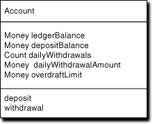
Also note that the knowledge responsibilities have an abstract data type (ADT) associated with them, such as Money. The “A” in ADT indicates we don’t care about how the knowledge is stored or physically represented. More important, at the level of abstraction of this class, each knowledge responsibility is represented as a scalar value of the ADT (i.e., the knowledge it abstracts is logically indivisible). For example, it is possible that for an international bank the notion of money is really a multivalued descriptor that includes things like currency name and exchange rate in addition to the number of units.
This notion of ADT is very important to raising the level of abstraction of knowledge to a level that is independent of the eventual computing environment. It enables us to think of value as a scalar such that any pair of values with the same ADT may be manipulated regardless of the actual complexity of their physical representation. That is, we can be completely confident that any valid manipulation for the ADT in our model will just work for any pair of attribute values when implemented at the 3GL or lower level. Conversely, it enables us to keep track of the apples-and-oranges aspects of our knowledge. Thus when we describe the dynamics of the model, we will know that a money value and a count value cannot interact because they are different things.
In UML we have the following definitions.6
A class attribute is a knowledge responsibility of the member objects that is expressed as a scalar ADT.
A class operation is a behavior responsibility of the member objects.
A class method encapsulates an implementation of a class operation that produces a result consistent with the implied behavior responsibility contract.
The notion of operation carries a lot of baggage related to algorithmic steps, which defeats the point of decoupling properties from implementations through the notion of responsibilities. In addition, the OO literature quite often employs method to refer to a behavior responsibility, dating from long before UML. Up to now this book employed the more conventional definition, that a method is a behavior responsibility. Henceforth, though, we will use the UML definitions to be clear about the distinction between responsibility and implementation.7
Identifying Classes and Their Responsibilities
In OOA/D we do not attempt to identify classes directly. There are actually several conceptual steps in getting the boxes onto a Class diagram:
- Identify problem space entities that are candidates for resolving the subject matter.
- Prune candidates that are redundant or not relevant to the problem the subject matter solves.
- Identify the intrinsic properties of the problem space entities that are relevant to the subject matter problem.
- Abstract the entity properties into object responsibilities.
- Identify classes to organize sets of objects.
Do we literally follow this five-step script to do these things? No. In practice, steps 2 through 5 tend to be mashed together because they are highly interrelated. For example, the typical reasons for pruning candidate entities is that they don’t have any intrinsic properties relevant to the problem (step 3) or there are other entities whose properties are more suitable to the problem in hand (steps 3 and 4).
The point here is that the list represents a suite of conceptual stepping-stones for migrating from the customer problem space to a Class diagram. As long as we generally follow this progression, things will tend to work out just fine. As it happens, the two most popular approaches to developing an initial cut at the classes in a Class diagram map closely to this sequence of steps.
Object Blitz
This is the most common form of developing an initial cut at a Class diagram, especially in a team development environment. It is actually based on consensus building techniques dating from the ’60s that were developed to support systematic process improvement (e.g., Total Quality Management [TQM] employs several variations). Usually it is executed with a team gathered around a white board. There are minor variations, but here are the basic steps.
- Gather candidate entities without prejudice. Team members throw out candidate entity names in a stream-of-consciousness manner. These are simply recorded (e.g., as a list on one side of the white board) without debate or justification. This usually takes only about five to ten minutes before team members run out of stream.
- Initial pruning. Each candidate is considered in turn. Whoever originally suggested it provides a brief (one to three sentences) explanation of what they had in mind. The team has a short discussion (usually limited by a moderator to one to two minutes) to determine whether the candidate is viable as described. If there is full consensus that it is not viable (relevant to the problem in hand), it is rejected. Lacking full consensus for rejection, it remains a candidate by recording it as the title on both sides of a 3 × 5 card.
- Definition. A definition is developed for each remaining candidate. It is usually better to delegate candidates to individual team members who write a preliminary definition for it to be scrubbed in the next step. The definition should describe what the entity is. The definition should be one to three sentences that describe what the entity is without details about what it knows or does. It is best for someone other than the original nominator to write the definition because this will immediately introduce a new perspective on what the entity is.
- Scrubbing. Each candidate’s definition is considered in turn. The team evaluates the definition and modifies it until a consensus is reached. The goal here is to gain a common understanding of what the entity is and how it is relevant to the problem in hand. Candidates may be rejected here if the scrubbing indicates that they are not relevant to the problem in hand. This should take one to five minutes per object.
At this point the 3 × 5 cards8 define the initial cut at classes for the Class diagram. The Object Blitz is more focused on classes than objects as compared to the previous script. That’s because recognition of entities and their generalization to classes of entities is essentially combined in a subliminal manner. (Remember: The class just defines properties of the member objects, so as soon as we have a single entity to abstract, we have a class to define.) Nonetheless, the progression from problem space entities to classes follows the conceptual script fairly closely.
All we have so far is a preliminary cut at classes. The details will undoubtedly change when we move on to identifying relationships and collaborations, which is why we can afford to place time limits on the various blitz steps to avoid analysis paralysis. If we don’t get through all the details now, they will be resolved later. However, we do have a framework for collaboration that is firmly anchored in the problem domain structure.
Gaining a consensus understanding of the problem space is at least as important as identifying classes and responsibilities.
The reason that the Object Blitz relies heavily on consensus-building techniques is to help provide that crucial understanding. In particular, it ensures that everyone on the team understands the problem space the same way. If you have never used consensus-building techniques, you will have a rude awakening in step 4 when you discover how varied individual perspectives on a seemingly familiar entity can be.
Because the Class diagram is the skeleton upon which the solution is draped, it is essential that the team developing a subject matter have a consistent view of the semantics of that skeleton. Things like object and responsibility definitions tend to be quite concise because documenting the software is a secondary concern. In effect, they are simply mnemonic devices for a deeper understanding of the problem space. This deeper understanding stems from participating in the discussions that produced the mnemonic descriptions. To gain that understanding we have to do the exercise rather than reading the results of someone else’s exercise.
Process note 1. In fact, the candidate classes developed in an Object Blitz provide a very good basis for project estimation. Because of the relatively fine granularity, the average effort time to develop classes is usually rather predicable (as is the 20% or so of new classes that will likely be identified subsequently). Typically, we can consistently estimate subsystem effort to within 5% to 15% once we have the Object Blitz results in hand. In one shop this was so successful that an Object Blitz for each designed subsystem was performed as a project planning activity rather than a design activity.
Process note 2. Because the Object Blitz is primarily focused on building team consensus about the software solution, most steps involve team discussion. Those discussions can easily get side-tracked, so to do Object Blitzes effectively some conditions must be met. The first is that there is a strong leader who can enforce limits on debates and cut off tangents. One of the most important things that the leader must enforce is that the team act like grown-ups. The goal here is a consensus on a truth that everyone can live with, not keeping score on who is right and who is wrong. The team leader must nip personal issues in the bud if they arise.
Another important condition is that some mechanism exist for resolving impasses where consensus cannot be reached. Ultimately that lies with the customer because the Class diagram is about abstracting the customer’s problem space. So the deciding vote on class definitions and responsibilities is always the domain expert. Ideally we would like a domain expert to participate in the Object Blitz and act as on-site arbiter.9 Lacking an in situ domain expert, there must be a mechanism for capturing open issues to get feedback from a domain expert.
Use Case Variant
If we have subsystem use cases for the requirements, then there are variants on the first and fifth steps of the Object Blitz that can make life easier. For the first step, the team essentially considers a small group of related use cases one at a time and uses the same stream-of-consciousness technique to identify objects that would be relevant to resolving the collection of use cases. The team can literally call out objects as they scan the use cases. For the fifth step, the team just uses the use cases as a guide to identifying responsibilities. When the Blitz step is done it should be possible to “walk” the use case steps and point to at least one object responsibility that resolves that use case step.
Note that proceeding incrementally should not introduce problems when different groups of use cases are analyzed subsequently. That’s because we are not defining a solution at this point; we are simply abstracting the problem domain structure. The underlying entities we abstract will still be there for subsequent use cases. If they are not relevant to the subsequent use cases, they can be ignored for those use cases. If they are relevant, then we just have more reason to abstract them.
Examples
In this subsection we develop some examples of identifying the classes for a given subject matter assuming an Object Blitz technique was employed. Because the next chapter is devoted to responsibilities, we limit the examples here to the first four steps in the Object Blitz. Even then we combine steps 3 and 4 because it is difficult to emulate group dynamics in a book. The examples will be carried forward for the remainder of the Object Blitz to the next chapter. Unfortunately, the specification of the subject matter requirements will be somewhat sketchy because there simply isn’t space to do a good job on a requirements specification, so we depend on your general familiarity with the subject matter to fill in the gaps.
The goal in going through these examples is to provide some clues into the way we think about problem space entities, objects, and classes, so these examples are an educational tool, not problem solutions. If you are faced with designing exactly the same subject matter as one of the examples, you still need to do your own Object Blitz. The devil is in the details, and you will very likely have at least some different requirements. Therefore, you need to deal with your problem space specifically rather than cribbing an example from a book like this.
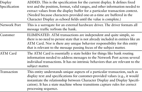
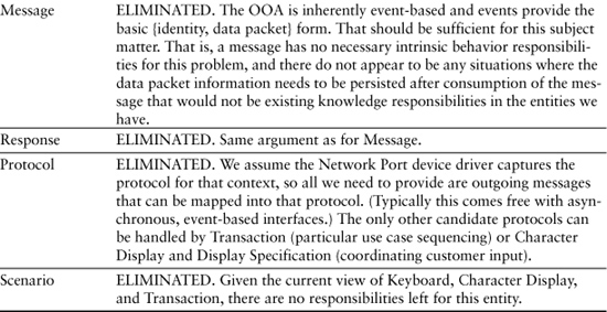
The Legendary Bank ATM Controller
This example is a favorite in the OO literature because the use cases are familiar to everyone who has an ATM card.
Subject Matter Definition
In Chapter 5 we indicated that the subject matter is that of message broker. This subject matter is really about reformatting and passing messages between the bank’s accounting or persistence software (behind the network port) and the various hardware drivers. Thus the subject matter’s decision making is based strictly on parametric information contained within the messages themselves. The decisions and sequences of operations map directly to use cases defined in the requirements and to handshaking protocols for security purposes (e.g., cash may not be dispensed until the bank software acknowledges posting).
Subject Matter Requirements
The bank ATM machine manipulates the following hardware elements: ATM card reader, input keypad, simple character UI, cash dispenser, an envelope processor, a receipt printer, and a network port. All banking decisions (e.g., whether a withdrawal request should be honored) and data persistence are handled by other subsystems on the other side of a network port.
The use cases can be summarized as follows. The customer is identified and then selects a transaction via the keyboard. When a customer transaction completes, the customer selects another transaction or logs off, and the ATM card is returned.
Each hardware element has its own realized device driver that handles basic operations appropriate for that driver. Though the UI is primitive, there will be another subsystem that deals with the mundane details of display. So this subject matter will communicate with that driver at the level of putString(...). Any response by the user will be through the keyboard. Synchronization between the keyboard and characters echoed to the display is handled by this subject matter.
Step 1: Get Candidate Entities
Normally this would be done with a stream-of-consciousness approach, but let’s introduce a smidgen of discipline by first considering the easy entities, those that are tangible things in the problem space. There are several in this subject matter, so they would tend to be first out in an Object Blitz anyway. That list might look like the following:
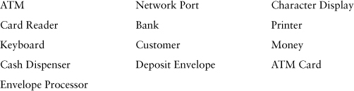
So far this is pretty straightforward; any domain expert (e.g., an ATM hardware vendor) will be able to instantly provide you with a definition of each of these things. Things get a bit more creative when we look at intangible candidates:
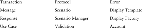
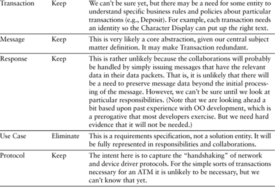
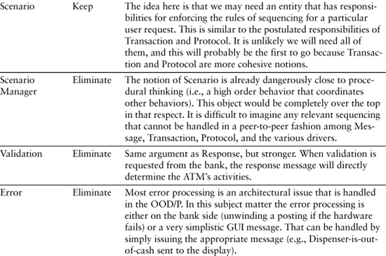
Some of these are a bit more obtuse (e.g., Scenario), so someone is going to have to put more words around them to understand how they fit into the solution. Also, you probably wondered why Use Case was in the list since it is a requirement description, not a solution entity. Remember, this preliminary list of candidates is without prejudice; no suggestion is rejected. The goal is to open the door to intuition, experience, and creativity to identify every entity that might conceivably be useful to the solution. That is best done free-form without any constraints or filtering, however well intentioned.
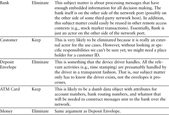
Step 2: Initial Pruning
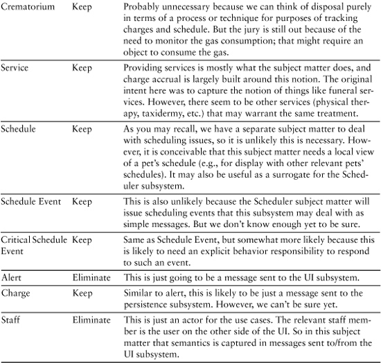
This sort of analysis for each of the candidates in Table 8-1 would be typical.
Table 8-1. Analysis of Candidate Objects
Steps 3 and 4: Define and Scrub Entities
In the initial pruning we provided cursory definitions. In these steps we provide definitions that the application will have to live with. While these aren’t written in stone because we are only scratching the surface of the solution, we still need to get everyone on the same page because that will make it a lot easier to identify responsibilities.
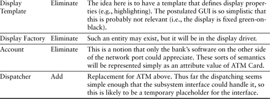
To do this properly, we have to anticipate responsibilities to some extent. The recommended way of doing this is to keep the use cases handy and envision which use case steps a particular entity would be involved with. This should be done at a very high level of abstraction though. We are not identifying responsibilities; we are just trying to understand the role the entity plays in the subject matter so that we can tailor the entity definition to that role. Table 8-2 provides the preliminary definitions a team might come up with for the remaining candidates.
Table 8-2. Candidates after Pruning
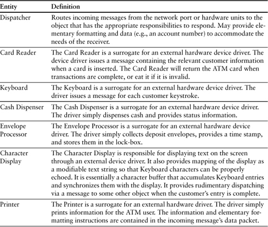
You will note that we have changed some definitions, added an entity, and eliminated some candidates. This is fairly typical of this stage as the team refines their view of the entities.
So What Is Missing?
If you have ever actually dealt with hardware controllers in general or ATMs in particular, you have probably already figured out that there is some stuff missing here. This is because there are other requirements that weren’t mentioned, many of which are implied. The goal here was to demonstrate how we think about the subsystem, not to create a viable ATM Controller design.
However, it is worth spending some time on what is missing to make a different point. Some of the things missing are the following:
• Start-up initialization. When the software starts up, the hardware must be put into a known state and hardware self-tests will have to be run. In addition, most of the objects in the subsystem will be instantiated once at start-up.
• Hardware self-test. The hardware components will likely have self-tests that should be run to ensure they are in working order at start-up.
• Routine system maintenance. Somebody collects deposit envelopes, puts money in the cash dispenser, and does other as-needed maintenance. Whoever does that will probably want to run the hardware self-tests from the terminal and see the results on the display.
• Error processing. There are lots of ways the hardware can go awry in this system, ranging from the cash dispenser being empty to the card reader jamming.
• Auditing. Banks are very big on audit trails. They want to be able to trace problems to individual transactions. Most of that will be on the Bank’s side of the network port. However, the Bank needs to be told about everything that goes on in the ATM Controller.10
Given our quite restrictive subject matter description, most of these things can probably be handled with a couple of new objects and some complexity in the dynamic description. What should concern you here is the level of abstraction.
It is quite possible that the provided hardware drivers will do a lot of this stuff so the ATM Controller can do its thing at a high level of abstraction that doesn’t include things like detecting time-outs. If you were writing the drivers, they would be in another subsystem where you could allocate such details during application partitioning to ensure a consistent level of abstraction in this subsystem. But if the drivers come with the hardware and they don’t do that sort of thing, then you may have a problem.
In that case you may want to consider providing a Hardware service subsystem where the individual driver surrogates live. Then the ATM Controller subsystem would just encode messages without knowing which hardware the messages were routed to. Now the ATM Controller can send a “time for self-test” message and get back either an “All’s well” message or a “Broken” message with a diagnostic code in its data packet. Similarly, it could send a “dispense N dollars” and get back either an “I did it” message or an “I couldn’t do it” message with a diagnostic code.
This enables our ATM Controller to provide very high-level control over what is going on that is more in keeping with our original vision of what the ATM Controller is about. Do you need a Hardware subsystem? That will depend on an analysis of the detailed requirements that weren’t specified and the sophistication of the device drivers.
Subsystem subject matters are almost always more complex than anticipated when doing application partitioning.
Another point of this digression on what was missing is that when you start to design a subsystem you may discover that it is too big, or that it has multiple levels of abstraction when you try to actually implement it. You will almost always recognize this when you do the sort of analysis described as you develop the Class diagram. If so, you break out some service subsystems.
Generally, it is easier to coalesce trivial service subsystems into their clients than it is to break up large subsystems after substantial effort has been devoted to their design. So when you are doing the Class diagram, if you even suspect things are getting out of hand you should reexamine your application partitioning. Since all you are doing is breaking out service subsystems that this subsystem talks to, you will not affect other teams working on other subsystems, and it won’t be difficult to get back to this model if it turns out that your concerns were unwarranted.
Pet Care Center: Disposition
Examples like the bank ATM are favorites of OO authors because the subject matter is largely familiar to any reader, so providing a lot of background information on the problem space is not necessary. The reason the Pet Care Center example is used here is to demonstrate that the OO approach is generally applicable, even for off-the-wall applications. We can make that point in this context with a single subsystem.
Subject Matter
The context here is a Pet Care Center in the mellowest part of Southern California. The Center will be a running example in the book because it has a lot of interesting activities. The most extraordinary activities, though, are associated with what to do with a pet that dies. Southern California has the highest density of pet psychiatrists in the world, so you can imagine the lengths pet owners might go to in honoring their departed pets. While the services of this subsystem might seem tongue-in-cheek, be assured that some pet centers really do provide such services.
The subject matter of the Disposition subsystem is to manage everything related to the pet that occurs after its course of treatment. That ranges from holding the pet until it is picked up by the owner to providing memorial services for deceased pets.
Subject Matter Requirements
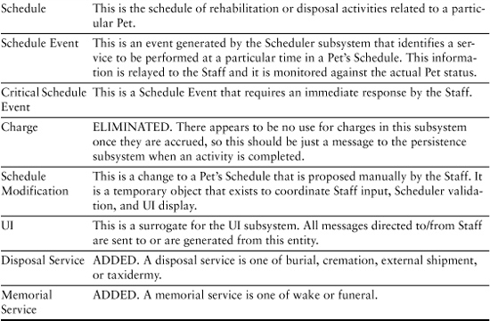
The requirements for this subject matter are pretty basic. The subsystem tracks pets after their treatment. It tracks any rehabilitation, such as physical therapy sessions, and notifies the owner when the pet can be picked up. In the event the pet does not survive treatment, it tracks any processing around its remains, like storage, cremation, burial, shipment elsewhere, taxidermy, and memorial services. The services are predefined and associated with the pet in the database.
A schedule for migration though the process stages is predefined. The Staff11 provides updates of status through the UI. The Staff needs to be alerted when critical schedule items are pending or when there is a schedule failure through the UI. The Staff can reschedule events (e.g., physical therapy sessions) when there is a schedule conflict. The Disposition subsystem will provide feedback on whether such changes are feasible, but the actual feasibility analysis will be in the Scheduler subsystem.
Charges for residence or storage are accrued on a daily basis based upon the facilities required. Other charges are on a per-service basis and are accrued when the service is completed. Charges for cremation are a fixed rate plus a charge for the natural gas used (based upon monitoring of the hardware).
The subsystem interacts with the Scheduler subsystem by processing alerts concerning the schedule, providing the Scheduler with status information, and providing revised schedule information. That is, the Scheduler has all the schedule management responsibilities, including detecting conflicts. This subject matter simply maps Scheduler’s events into notices for Staff.
Step 1: Get Candidate Entities
An initial Object Blitz might result in the following list of candidate entities that are important to the subject matter (this time without segregating tangible from intangible):
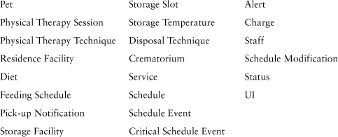
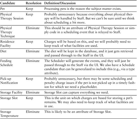
Step 2: Initial Pruning
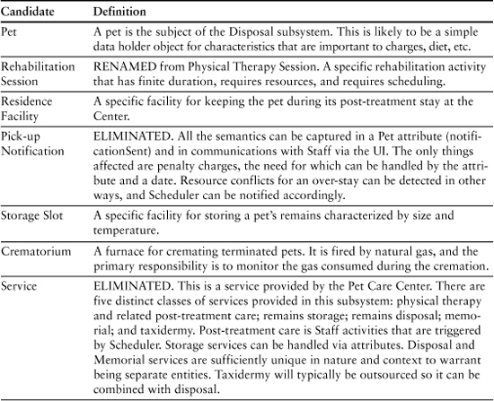
Essentially we follow the same pattern as we did for the ATM example. Table 8-3 reflects the probable results of this step.
Table 8-3. Candidates from Object Blitz
Steps 3 and 4: Definition and Scrubbing
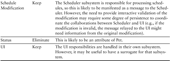
Continuing the Object Blitz exercise, we might arrive at the results of the preliminary entity definition, shown in Table 8-4.
Table 8-4. Preliminary Object Definition
A Few Final Points
At the beginning of the example we said the choice of the Disposition subsystem of the Pet Care Center was deliberate to demonstrate that the OO approach is generally applicable no matter how bizarre the subject matter. In this subject matter we are talking about physical therapy, cremations, taxidermy, and memorial services for pets. Yet the subject matter is readily described and abstracted. The deadpan description of the problem space analysis should make it clear that this is actually pretty mundane stuff.
In particular, note that with the exception of Pet and Memorial Service, all of the entities identified could have shown up with those same names in an application for the waste management industry. The text definitions of what they were would be somewhat different, but such definitions aren’t directly implemented in software. In software we implement objects, relationships, attributes, computational procedures, and messages. Those things are always the same regardless of the problem spaces that they resolve. As long as there is a mapping between the things implemented in software and the problem space, the software will just work no matter how strange the problem space is. That is, the mapping is an exercise in design creativity for the software developer, but the OO artifacts of problem space abstraction are quite pedestrian within the paradigm.
Using Sequence and Collaboration Diagrams
If you are vaguely discontented about these examples, you should be. We’ve identified a lot of messages and dumb data holders but nothing so far gives us a warm and fuzzy feeling that these objects will resolve the subject matter properly. In particular, you will recall that when abstracting entities and their qualities we need to solve the problem in hand. How can we do it without some vision of what the solution is? The short answer is that we can’t. There will be more said about this in the next chapter when we talk about identifying responsibilities. But we have the same problem here with simply deciding what problem space entities to abstract as objects.
One common way around that is to develop a very high-level Sequence diagram12 as we construct the Class model. The candidate objects are put on the swim lane boundaries of the Sequence diagram, and then we note collaborations on the diagram as horizontal connections. The key is to not think about specific messages. Instead, we just use the Sequence diagram to jot notes on the collaborations. As we do this we talk through what each object’s role is for that collaboration. The best way to do this is by tracing use cases through the Sequence diagram as shown in Figure 8-2 for the Pet Care Center: Disposition example.
Figure 8-2. Sequence diagram for collaborations among Pet, Schedule Event, Schedule, and UI entities
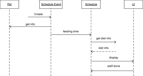
This exercise provides two important things. One is obviously that we can validate a plausible sequence of collaborations that will solve the problem (use case scenario). The more subtle benefit is that we ensure that we have abstracted all of the entities we need to solve the problem in hand. That is, there are no swim lanes missing where one has no plausible collaboration to get to the next use case step. The crucial thing is to avoid getting carried away identifying messages. The use of the Sequence diagram that is suggested here is much more general, and it is intended to merely assist in the primary task of identifying classes and their responsibilities. To that end, let’s see how we might “walk” a simple use case like the one that follows.
Use Case: Respond to feeding event from Scheduler.
- Get diet data for indicated Pet.
- Send message to Staff that it is time to feed pet; include diet information.
- When Staff acknowledges feeding completed, generate charge and notify Scheduler.
What objects are likely to be involved? Let’s go with Pet, Schedule, Schedule Event, and UI to see if they can do the job. When the external event is received from the Schedule subsystem we create a Schedule Event object and put the relevant data in its attributes. Schedule Event then announces it is there to the Schedule object.13 Let’s assume Schedule knows what’s involved in a feeding scenario (i.e., the actual object is a Feeding Schedule14) so Schedule will respond by sending a query to the database to get the diet information.
Oops. We have a surrogate for the UI but we don’t have one for the database. A physicist’s sense of symmetry says we are missing an object for the database surrogate. In this case it probably isn’t a problem because the message is quite simple; the message identifier and Pet identity will convey everything the database needs to know. So these messages may be sent directly to the Persistence subsystem. (In the UI case the messages have more data, and we may need a state machine for handshaking with the Staff.) However, this sort of inconsistency should cause you to at least reconsider things.
Let’s assume the database sends back an event with the diet information in the data packet. It will get dispatched by the subsystem interface to the Schedule object. The Schedule object then sends a message to the UI so the Staff can be notified. That message will have an identifier to indicate a feeding, and the data packet will have the Pet identity and the diet information. The UI object will forward that to the display and wait for a response from the Staff (in the form of another external event). When that response is received, it will generate a message so that the charge can be logged.
Oops, redux. Who is going to log the charge? We probably don’t need another object because we already designated Schedule as being the major domo of the feeding process. Thus the acknowledgment that the feeding has been done can be sent directly to Schedule, which will compute the meal charge and send it off to the database.
Also note that the “get info” collaboration between Schedule Event and Pet doesn’t have a response. That’s because all Schedule Event is obtaining from Pet is knowledge it needs to talk to Schedule. In fact, Schedule might well do that directly. At this point we don’t care because all we need is a plausible path through the use case. As it happens, one usually does not put pure knowledge collaborations on Sequence diagrams because they tend to clutter things. But “get info” is useful here because it covers a use case base (i.e., we need to know what type of Pet or what type of diet the Pet needs to ask the database the right question, and Pet would logically have that kind of knowledge).
It is now worth considering what Schedule’s role is in all of this. It doesn’t actually do very much except send messages, but the sequencing of those messages is very important. In effect, the use case defines rules for the sequencing that need to be followed. What Schedule does is enforce those rules. It is getting ahead of the story, but Schedule’s main contribution here is to own a state machine whose transitions enforce the sequencing rules of the use case. That, in turn, ensures that the collaborations are done in the right order because Schedule needs to receive a specific triggering message to send the next message to someone else.
Something even more interesting about Schedule is that the notion of schedule has been highly tailored. This is not a schedule in the sense of a sequence of feedings at specific times; this sort of schedule is the Scheduler subsystem’s problem. Here the notion of schedule is about the sequence of steps in a single feeding that must be performed to respond to Schedule Event. That is a pretty unique view of schedule compared to the way the term was used in the requirements, so we are abstracting a different problem space concept.
We probably would not have gotten to that concept from just the blitz scrubbing. It took the analysis of “walking” the Sequence diagram to get there. If somebody brought in a few six-packs and the team sat around awhile thinking about responsibilities, they might get there. They would certainly get there after stumbling around with the dynamics for awhile, but “walking” a use case through a Sequence or Collaboration diagram such as the one in Figure 8-2 would essentially demand that sort of view very early in the development.