
Chapter 4
Atomic Absorption Spectroscopy
INTRODUCTION
Atomic absorption spectroscopy (AAS) is defined as the measurement and interpretation of the absorbed radiation in atomic level. This method is widely used for the determination of the elements. Robert Wilhelm Bunsen and Gustav Robert Kirchoff first proposed the AAS theory. Alan Walsh first introduced the principle of AAS.
PRINCIPLE
The atoms present in the ground state absorb the radiation produced by the flame and excited to the excited state and which is measured by the AAS spectrometer. Atomic absorption measures the amount of light at the wavelength which is absorbed by the atoms. Atoms present in the sample are directly proportional to the absorption intensity.

Schematic diagrams for the atomic absorption
Steps involved in the AAS:
There are mainly three steps involved in the AAS:
- Desolvation by evaporating the solvent present in the sample and leaves the sample completely dry.
- Vaporising the evaporated solid sample into the gas or vapour.
- Voltalisation by breaking the vaporised sample into the free atoms.
THEORY
AAS is used to determine the absorbed light which directly gives the concentration of the element present in the sample. The absorption is directly proportional to the concentration which is derived from the Beer–Lambert's law.
The total amount of absorbed light is given by
where e is the charge; m is the mass of the electron; c is the speed of the light; N is the total number of atoms; f is the oscillator strength; Π, e and m are constants hence the equation becomes
INSTRUMENTATION
The AAS contains the following components:
- Radiation source
- Atomiser
- Chopper
- Monochromator
- Detector
- Amplifer and recorder
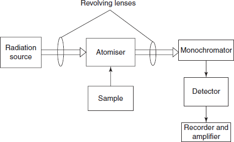
Schematic diagram for the atomic absorption spectrometer
- Radiation source:
The radiation source of AAS should posses the following characters:
- Stable radiation.
- Intense radiation.
There are two types of radiation sources used in the AAS.
Hallow cathode lamp: This is the most frequently used radiation source in AAS. This consists of a sealed glass tube which in turn consists of tungsten anode and cylindrical cathode with quartz window and the rest of the glass tube is filled with argon gas at low pressure.
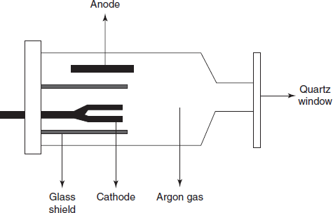
Diagram for the hallow cathode lamp
Electrode less discharge lamp: This is rarely used because of its high cost and less sensitivity. It consists of quartz tube containing inert gas and metal. This metal is excited with the radio frequency coil.
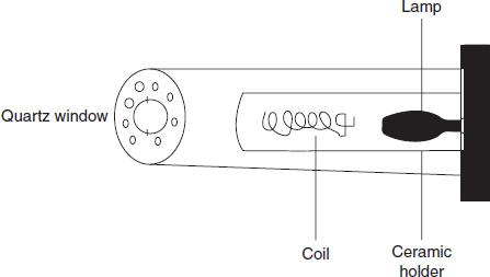
Diagram for the electrode less discharge lamp
- Chopper: The main use of the chopper is that the beam produced by the source when hits the solid surface of the chopper blocks the beam of incident light after rotating the chopper and allows the beam to enter into the detector.
- Atomisers: The following are the steps involved in the atomisation:
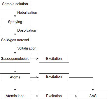
Steps involved in the atomic absorption spectroscopy
There are two main types of atomisers used in the AAS.
- Flame atomiser: Sample is evaporated by the desolvation process where the solvent is completely evaporated. Then the solids are vaporised into the gaseous state. This vapour is atomised into atoms and followed by ionisation. This forms the ions which are readily excited to the higher energy states. To attain the atomisation, fuel and oxidants are used, for example, hydrogen and air which produces at 2000–2100 °C.
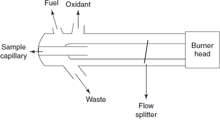
Schematic diagram for the atomiser
- Electro thermal atomiser: These are more sensitive than the flame atomisers. The process is as follows. Initially the sample is evaporated to remove the solvent. The solid particles are ashed to burn the organic matter and followed by atomisation to form atoms. It requires small amount of sample.

Schematic diagram for the electro thermal atomiser
- Monochromator:
Generally prism and grating monochromators are used. The main use of monochromator is to convert the polychromatic light to monochromatic light.
- Detectors:
The detector commonly employed in the AAS is the photomultiplier tube. Electrons from the photocathode are attracted to anode 1 and liberate more electrons which trowel towards anode 2 and continue till the last anode. The final current of 106–108 times is greater than that of primary current.
- Amplifiers and recorders:
From the detector, the electric current produced is amplified with AC amplifier and DC ampli-fer amplifies and the difference in the frequency is summarised and recorded with the help of recorder.
INTERFERENCES IN AAS
There are mainly three types of interferences:
- Spectral interferences such as spectral overlap, molecular absorption and light scattering.
- Chemical interferences such as thermal stability of the sample and the ionisation ability of the molecules present in the sample.
- Physical interferences such as viscosity, density and surface tension.
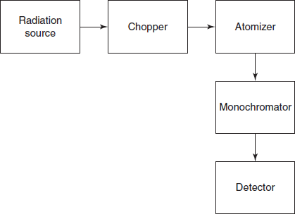
Single-beam atomic absorption spectrometer: In this, the radiation source is connected to chopper and then to atomiser which is connected to the monochromator. The signal is detected by the detector and recorded by the recorder.
Double-beam atomic absorption spectrometer: The radiation source is connected to the chopper then it splits the incident beam into two paths one is to the sample and another to the reference. These two are connected by the monochromator which measures the difference in the intensity of the sample with that of the reference. Then the signals are detected by the detector and recorded by the recorder.
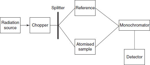
Schematic diagram for the double beam AA spectrometer
ADVANTAGES
- High sensitivity.
- High accuracy.
- High selectivity.
- Wide applicability.
- Highly specific.
DISADVANTAGES
- Non-metals are not handled by the AAS.
- Time consuming.
- Expensive method.
- Thermal interference.
- Each sample should be analysed separately.
- Relative precision is low.
APPLICATIONS
- Used in the analysis of trace elements in steel.
- Used in the quantitative determination of potassium in fertilisers.
- Used in the determination of arsenic in food components.
- Used in the analysis of oil for silicon.
- Used in the determination of water purity where the contamination with trace elements are determined.
- Used in the moisture content analysis.
- Used in the gas analysis for purity.
- Used in the determination of lead in petrol.
- Used in the analysis of the soil.
- Used in the determination of the As and Cd elements.
- Used in the analysis of additives.
- Used in the clinical analysis.
- Used in the detection of the metal particles present in the parenterals.
REVIEW QUESTIONS
- What is the light source used in the AAS?
- What is the purpose of monochromator?
- What is the basis for AAS?
- What is the purpose of atomiser?
- What are the advantages of AAS?
- What are the applications of AAS?
- What are the different types of the AAS spectrometers?