
Chapter 6
Gas Chromatography
INTRODUCTION
Gas Chromatography (GC) was invented by A. J. P. Martin. Martin and Synge recommended that the liquid mobile phase used in liquid chromatography could be replaced by a suitable gas. Fritz Prior first developed the solid-state gas chromatography. A more sophisticated form of the gas chromatography was constructed by James and Martin and described by James in 1955.
PRINCIPLE AND THEORY
The GC is the chromatographic technique where the sample is vapourised by the injection into the heated column by a inert gaseous mobile phase. In this technique, the mobile phase is the gas and the stationary phase is the solid or liquid. If the stationary phase is liquid then it is called as the gas-solid chromatography. When the stationary phase is the liquid then it is called as the gas-liquid chromatography. This method is mainly used for the separation of the volatile substances which are not conveniently handled by the High-Performance Liquid Chromatography (HPLC).
TYPES OF GC
There are two major types.
- Gas-solid chromatography: Where the stationary phase is the solid that is adsorbents such as alumina, silica, active carbon, etc. The main advantage of this method is the long column life times. The main disadvantage is the catalytic changes are observed in this technique.
- Gas-liquid chromatography: Where the stationary phase is the immobilised liquid which is coated on the solid support such as polymers. The main disadvantage of this method is that the liquid slowly bleed off with time.
INSTRUMENTATION
The instrumentation consists of the following components:
- The carrier gas
- Temperature programmer
- Pressure regulator
- The injection port: To introduce the sample
- The column
- Detectors
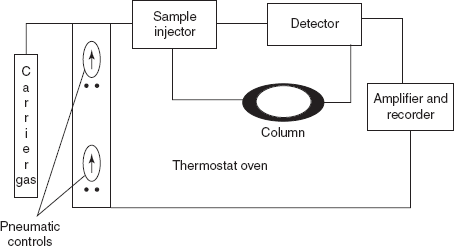
Flow chart of the GC instrument
- Carrier gas: The carrier gas is mainly used as the mobile phase to carry the sample into the column. The most widely used carrier gases in the GC are the following:
Examples: Hydrogen: This has more advantages. Helium: This is expensive but used most commonly because of it thermal conductivity, inertness and low density. Nitrogen gas: It is inexpensive but reduced sensitivity. The most important ideal requirements of a carrier gas are the following:
- It should be chemically inert.
- It should be available at low cost because large quantities are used.
- It should allow the detector to respond in an adequate manner.
- It should be non-explosive.
- It should be free from metallic particles.
- It should be in the pure form.
- Temperature programmer: The column is placed in thermostatic oven. There are commonly two temperature programmers used. They are as follows:
- Isothermal programming: The temperature is kept constant during the entire analysis.
- Gradient programming: The temperature is differentiated that it is increased or decreased during the analysis.
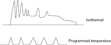
Temperature programming peaks
The following factors should be considered during the temperature programming:
- Solubility of solutes
- Volatility of the solutes
- Stability of the solutes
- Stability of the stationary phase
- Change in the flow rates
- Pressure regulator: The pressure regulator is mainly used to regulate the pressure in the range of 10-50 psi for the flow of carrier gas with flow rate of 25-150 ml/min with packed column or 1-25 ml/min for open tubular column.
- Sample injector system: The sample injector system is mainly used to introduce the sample into the carrier gas flow to the column. In GC, the sample injector system used is mainly based on the state of the sample. They are as follows:
- For gaseous samples: For gaseous samples, the rotatory valve is used which is same as the HPLC except the sample loop is larger in the GC. The ideal method for the sample introduction is that the sample is injected through a narrow column where the peak broadening is negligible.
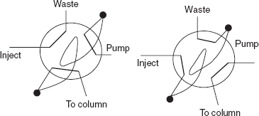
Sample injector system
The sample injection port contains the six-port valve. In the load position, the mobile phase flows directly to the column through one pair of the ports. The other ports drain the sample from the sample loop. Then the rotation of the valve to the inject position directs the mobile phase flow into the sample loop and injects the sample into the column.
- For liquid sample: For liquid samples, a gas syringe is used. Sample is introduced or injected with a 1.5-10 μm graduated syringe through septum into the heated flash evaporation injector. Then the sample is vapourised and the carrier gas pushes the vapourised sample from the injector to the column.
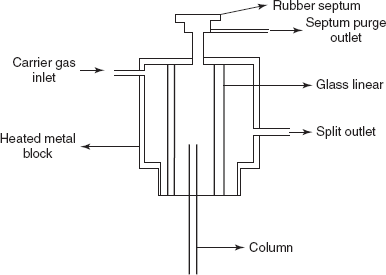
Septum injector
- For solid samples: For solid samples, the samples are initially volatilised to convert the sample into volatile derivative. In some cases, pyrolysis is used to vapourise the solid sample. The pyrolysis is nothing but the sample is heated to 270 °C after placing it in the injection port and the vapourised sample is again heated to 1,000 °C.
Commonly used inlet types are the following:
- S/SL (split/split less) injector: A sample is introduced into a heated small chamber through a syringe into a septum. The heat facilitates volatilisation of the sample and sample matrix. The carrier gas then pushes entire or the portion of the sample into the column. In split mode, a part of the sample/carrier gas mixture in the injection chamber is exhausted through the split vent. Split injection is used when the samples are with high analyte concentrations (>0.1%), whereas split less injection is best suited for trace analysis with low amounts of analytes (<0.01%).
- On-column inlet: In this, the sample is introduced with out heat.
- PTV injector: Temperature-programmed sample introduction was first described by Vogt in 1979. This method was mainly used to introduce the large sample volumes.
- Gas source inlet or gas switching valve: This is mainly based on the sample introduction by the six-port valve. The carrier gas is flowed continuously to avoid the interference. The switching of the column allows the contents of the sample loop and the contents are then inserted into the carrier gas stream.
- P/T (purge-and-trap) system: An inert gas is bubbled through an aqueous sample causing insoluble volatile chemicals to be purged from the matrix. The volatiles are ’trapped’ on an absorbent column (known as a trap or concentrator) at ambient temperature. The trap is then heated and the volatiles are directed into the carrier gas stream.
- For gaseous samples: For gaseous samples, the rotatory valve is used which is same as the HPLC except the sample loop is larger in the GC. The ideal method for the sample introduction is that the sample is injected through a narrow column where the peak broadening is negligible.
- Columns: The columns are mainly used to separate the sample components. So column is the heart of the GC. There are mainly two types of columns used in GC. They are as follows:
- Packed columns: These contain the metallic or glass tubes packed with the stationary phase. The column diameter should be 1.5-10 mm and an internal diameter of 2-4 m. The solid support material (e.g., diatomaceous earth) that is coated with a liquid or solid stationary phase.
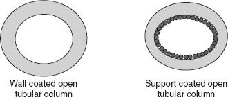
- Capillary columns: These have a very small internal diameter of millimetres and lengths between 25 and 60 m. These are also called as the open tubular columns. These columns contain the liquid stationary phase coated on the inner walls of the glass or fused silica column. These columns length should be 10-100 m and the diameter should be 0.2-0.5 mm. These are the following two types:
- Wall-coated open tubular columns: These column walls are coated with the inert active materials.
- Support-coated open tubular columns: These columns are coated with the micron size porous layer of the support material which is coated with the thin film of the liquid phase. These columns have the more sample capacity.
Types of columns
New developments are sought where stationary phase incompatibilities lead to geometric solutions of parallel columns within one column. Among these new developments are noted:
- Internally heated micro FAST columns, where two columns, an internal heating wire and a temperature sensor, are combined within a common column sheath (micro FAST).
- Micro packed columns (1/16 in. OD) are column-in-column packed columns where the outer column space has a packing different from the inner column space, thus providing the separation behaviour of two columns in one. They can easily ft to inlets and detectors of a capillary column instrument.
Retention time: The retention time is the time taken for the solute to travel through the column. This corresponds to the solute peak. This is nothing but the sum of the time spent in the stationary phase and the mobile phase.
Column bleed: This is nothing but the continuous elution of the compounds produced from normal degradation of the stationary phase. This increases with the temperature increase.
- Columns should have lower and upper temperature limits. If a column is used below its lower temperature limit, wide peaks are observed that is nothing but it loses the efficiency.
- Using the column at or above its lower limit maintains good peak shapes.
- Upper temperature limits are often stated as two numbers. The lower one is the isothermal temperature limit. The column can be used indefinitely at this temperature and reasonable column bleed and lifetime are realised.
- The upper number is the temperature program limit. A column can be maintained at this temperature for 10–15 min without severely shortening column lifetime or experiencing excessively high column bleed.
- Exposing the column to higher temperatures or for longer time periods results in higher column bleed and shorter column lifetimes.
- Exceeding the upper temperature limits may damage the stationary phase and the inertness of the fused silica tubing.
Column capacity: This is the maximum amount of the solute that can be introduced into a column. When the column is over loaded, the tailing of the peaks is observed and sometimes shows the asymmetric peaks with leading edge. Sometimes damage is occurred when the column is overloaded.
Causes of Column Performance Degradation
Column breakage: This is mainly caused by the weak coating of the coating material. The continuous heating and cooling of the column cause the breakage. The large diameter columns are more prone to breakage. Thus the acceptable diameter is 0.45–0.53 mm.
Thermal damage: When the column is heated to the higher temperatures causes the degradation of the stationary phase and the tubing surface. This shows the peak tailing and the column bleed. The thermal damage is increased in the presence of the oxygen. This can be prevented by the maintenance of the column temperature above its limit and by setting the maximum oven temperature. If a column is thermally damaged, it may still be functional. Remove the column from the detector. Heat the column for 8–16 h at its isothermal temperature limit. Remove 10–15 cm from the detector end of the column. Reinstall the column and condition as usual.
Oxygen damage: The constant exposure of the oxygen causes the damage to the column. The source of this damage is the leak in the carrier gas flow path. The oxygen damage decreases the performance of the column. The damage by the oxygen is irreversible. This is prevented by the maintenance of the oxygen and leak-free system.
Chemical damage: This damage is caused by means of the chemical compounds. The following are the chemical compounds that damage the column:
- Introduction of the non-volatile compounds into the column.
- The acids such as HCl, H2SO4, HNO3, H3PO4, and chromic acid.
- The bases such as KOH, NaOH, NH4OH, etc.
- The organic compounds such as perfluoro acids.
Examples: Trifluoro acetic acid Penta fluoro propionic acid Hepta fluoro butyric acid
This chemical damage is avoided by the use of the guard column. The chemical damage shows the change in the peak shapes.
Column contamination: The column contamination is observed by the two contaminants. They are as follows:
- Non-volatile contaminants: These are observed when the residues present in the column are interacted with the active solutes such as hydroxyl or amine or thiols and aldehydes and results in the peak tailing or loss of peak size.
- Semi-volatile contaminants: These are caused by the residues that accumulate in the column which causes the increase or decrease of the peak shape and peak size.
The contaminants originate from the number of sources such as biological fluids, tissues, soils and waste. Sometimes these are originated from the gas lines and traps, injection systems, solvents and pipettes. This contamination is prevented by the minimisation of the semi-volatile and non-volatile sample residues.
The column is eventually rinsed with the solvent to remove the contaminants.
- Stationary phases: These are mainly used to adsorb or partition the sample components based on their ability by moving with the mobile phase such as carrier gases. These are mainly of two types. They are as follows:
- Solid stationary phases: These should have the inert surface to which the liquid phase should be coated. It should be thermally stable and should contain uniform size particles.
Examples: Polysiloxanes: These are commonly employed stationary phases. These are mainly of methyl substituted. Polyethylene glycols: These are also widely used as stationary phases but their uses are limited because of the less stability to temperature changes than the polysiloxanes. - Liquid stationary phases: These should be non-volatile and pure.
- Solid stationary phases: These should have the inert surface to which the liquid phase should be coated. It should be thermally stable and should contain uniform size particles.
- Detectors: The detectors are mainly used to detect the differences of the elution of the pure gas and the carrier gas is mixed with the sample. The following are the ideal requirements of the GC detectors:
- It should have the high sensitivity.
- It should have the high stability.
- It should have the high reproducibility.
- It should be feasible with wide range of temperature.
- It should be easy to handle.
- It should not cause any decomposition of the sample.
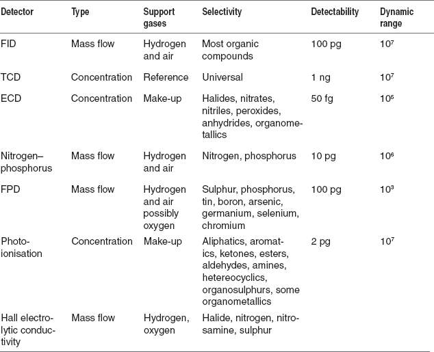
The number of detectors is used in the GC. The most commonly employed detectors are the following:
- Thermal conductivity detector (TCD)
- Flame ionization detector (FID)
- Flame photometric detector (FPD)
- Electron capture detector (ECD)
- Thermionic detector
Among these, both FID and the TCDs are more sensitive to a wide range of the samples and concentrations. The other types of detectors are applicable to the specific substances and the low concentrations. They are as follows:
- Catalytic combustion detector: It is mainly used to measure the combustible hydrogen and the hydrocarbons.
- Discharge ionisation detector (DID): It uses a high-voltage electric discharge to produce ions.
- ECD: It is mainly used to measure the degree of electron capture.
- Thermionic detector.
- FPD, etc.
Different detectors show the different types of selectivity. A non-selective detector responds to all compounds except the carrier gas, a selective detector responds to a range of compounds with a common physical or chemical property and a specific detector responds to a single chemical compound.
Detectors can also be classified as follows:
- Concentration dependant detectors: The signal from a concentration-dependant detector is related to the concentration of solute in the detector.
- Mass flow dependant detectors: Mass flow-dependant detectors usually destroy the sample, and the signal is related to the rate at which solute molecules enter the detector. The response of a mass flow-dependant detector is unaffected by make-up gas.
Table for the detectors parameters
TCD: The principle involved in the TCD is mainly based on the thermal conductivity of the gas. It is used as universal detector in the GC. That is the rate of heat loss from a heated wire placed in the gas stream depends on the thermal conductivity of the gas. This detector is mainly used to detect the hydrocarbon and the inorganic salts. The main disadvantage of this detector is the less sensitivity. The possibility of the TCD as GC detector is explained by Ray.
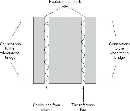
Katharometer
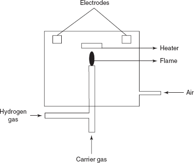
FID: The main principle involved in this is the ionisation of the sample by the air-hydrogen fame. This is more sensitive and applicable to the wide range of concentrations than the TCD. The carrier gas emerging from the column is mixed with the equal amount of the hydrogen gas and burned at a metal jet. The main disadvantage of this type of detector is that the sample is destroyed and it does not respond to the inorganic compounds. The FID is first explained by the Harley and Pretorius. The fame is surrounded by the cylindrical electrode.
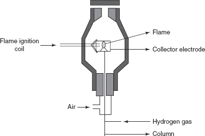
Flame ionisation detector
FPD: The main principle is same as the FID except the use of the photo multiplier tube for the measurement of the emitted radiation by the sample fame. In this detector, nitrogen is commonly employed as the carrier gas.
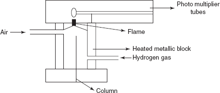
Flame photometric detector
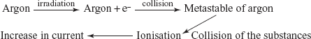
Ionisation detectors: The ionisation detector utilises the noble gases such as argon gas to produce metastable argon atoms which have sufficient energy to ionise most organic compounds. This metastable atom has no charge but absorbs the energy from the collisions with a high electron by the displacement of the electron. The main advantage of this detector is the high sensitivity. The main disadvantage is that the linearity is very poor.
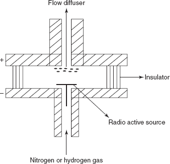
ECD: The main principle involved in this detector is that the capturing of the electrons by the compound produced by the collision between the β-particles and the carrier gas. In this, the radioactive sources used are titanium foil containing adsorbed tritium. The advantage is the high sensitivity. The main disadvantage is that it is only used for the compounds with the electron affinity.
Electron capture detector
Helium detector: This is same as the argon ionisation detector.
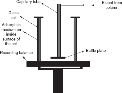
The absolute mass detector: The absolute mass detector adsorbs the material as it is eluted from the column onto a suitable adsorbent and continually weighs the mass adsorbed.
Absolute mass detector
Dielectric constant detector: This detector is first described by Winefordner that the dielectric constant of the carrier gas is measured when the sample is present. The main advantage of this detector is the linear response. This consists of the sensor which is placed between the conductors. This detector is mainly used for the detection of oxygen, nitrogen, hydrogen and methane.
Discharge detector: This is first developed by the Harley and Pretorius. The main principle in this detector is the application of the appropriate potential causes the discharge between the two electrodes placed in a gas. Then the electrode potentials are reduced and the discharge is continued.
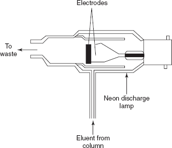
Discharge detector
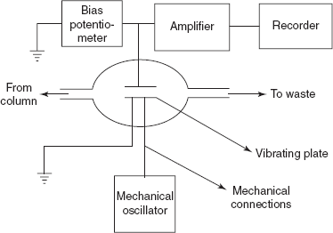
Piezoelectric adsorption detector: The principle is mainly based on the frequency output from the piezoelectric material which is influenced by the weight of the layers on the surface. This detector is introduced by King. This consists of the quartz crystal coated with a high boiling liquid which is placed in the electric circuit which causes the oscillations. This frequency is monitored by the separate circuit. As the sample is eluted, it is absorbed on the coating and weight of the crystal is determined.
The relationship between oscillation frequency (f) and weight (w) absorbed is given by the following equation:
f = f0 − 2.3×10⁻⁶ ×(f02)W /Awhere f0 is the natural frequency of the coated crystal; A is the total area of the coated crystal surface.
Therefore
Δf = 23×10−6×(f02)W/ASurface potential detector: This is first developed by Griffiths and Phillips. It consists of two metal plates which are placed in the cell. Between the plates, the sample eluent is placed.
Surface potential detector
Thermionic ionization detector: This detector is first produced by Ryce and Bryce in 1957. The main principle involved in this detector is the ionisation of an alkali metal salt. This metal salt is ionised by the fame. This is created by suspending the salt-coated wire in the fame or placing a cylinder filled with salt as compressed disc on the top of the fame.
Thermionic ionisation detector
Thermal argon detector: This is same as the argon detector in which the electron producing source by the argon and the sensor system which is operated at 150 °C.
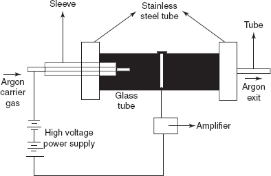
Thermal argon detector
- Recorders:
Two devices are used to record the GC traces/areas under peaks. They are as follows:
- Integrating recorders
- Computer program
This recorder is used to interpret and draw the data from the detectors as the peaks. Then the retention time and the area under curve are calculated.
Derivatisation of the Sample
This is the technique used for the treatment of the sample to increase the separation efficiency by the column or detection by the detector. This technique is of two types. They are as follows:
- Pre-column derivatisation: This is mainly used to enhance the separation performance of the column. This is carried out by converting the samples into more volatile and thermo-stable derivatives. The following are the conditions where the precolumn derivatisation is required:
- If the compound is less stable.
- If the compounds are less volatile.
- To reduce the tailing.
- To improve the separation factor.
- Post-column derivatisation: This is mainly used to enhance the detector performance.
FACTORS THAT AFFECT GC SEPARATIONS
Efficient separation of compounds in GC is dependent on the compounds travelling through the column at different rates. The rate at which a compound travels through a particular GC system depends on the factors listed below:
- Volatility of compound: Low boiling (volatile) components will travel faster through the column than the high boiling components.
- Polarity of compounds: Polar compounds will move more slowly, especially if the column is polar.
- Column temperature: Raising the column temperature speeds up all the compounds in a mixture.
- Column packing polarity: Usually, all compounds will move slower on polar columns, but polar compounds will show a larger effect.
- Flow rate of the gas through the column: Speeding up the carrier gas flow increases the speed with which all compounds move through the column.
- Length of the column: The longer the column, the longer it will take all compounds to elute. Longer columns are employed to obtain better separation.
PARAMETERS
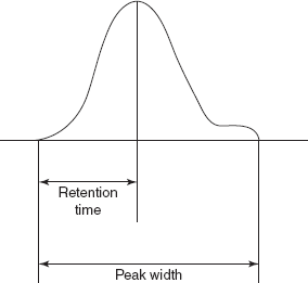
Adjusted retention time (tR′): The adjusted retention time is the time that a compound spends in the stationary phase. The adjusted retention time is the difference between the dead time and the retention time for a compound. The retention time is the difference between the time of injection and the time of peak appearance.

Retention time peak
where tr is the retention time; tm is the dead time.
Capacity factor (K): This is the ratio between the weights of the compound in the stationary phase and the weight of the compound in the mobile phase. That is given by the following:
Phase ratio: This is the ratio between the column diameter and the thickness of the stationary phase. It is also called as the volume ratio (β)
where r is the column diameter; df is the thickness of the stationary phase.
Separation factor: This is the ratio of the partition co-efficient of the two components which are to be separated. This is denoted by the S.
where Kb and Ka are the partition co-efficient of the compounds a and b.
The separation factor is more when the difference between the partitions co-efficient is more. The separation factor is less when the two compounds partition co-efficient are same. The separation factor is also given by the ratio between the retention time of a compound and the retention time of the b compound.

Separation factors
Efficiency: This is mainly related to the solutes peak width. This is expressed by the number of theoretical plates. A theoretical plate is defined as the hypothetical unit of the column where the solute distribution between stationary phase and mobile phase attains the equilibrium. The efficiency is determined by the following equation:
where N is the number of theoretical plates; Rt is the retention time; w is the peak width.
Efficiency evaluation peak
The number of theoretical plates is directly proportional to the efficiency that is when the number of theoretical plates is high represents the high column efficiency.
Height equivalent theoretical plates: This is mainly used to compare the column efficiencies with different lengths of the column.
where L is the length of the column; N is the number of theoretical plates.
HETP is given by the Van Deemter equation:
where A is the Eddy's diffusion coefficient. This is obtained by the multiple flow paths taking place through a packed column which leads to peak broadening. This depends on the size of the packing material and diffusion rate of solute B is the molecular diffusion coefficient; C is the mass transfer coefficient; μ is the velocity.
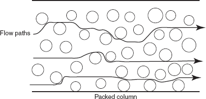
Mechanism of Eddy's diffusion
ADVANTAGES
- Very good separation
- Less time consuming
- Small sample is required for the analysis
- High sensitive detector systems
- Linearity is good
- High precision
- Simple to handle
DISADVANTAGES
- Low sensitivity
- Voltalisation is required for the analysis without decomposition of the sample
- Biological samples cannot be handled
APPLICATIONS
- Used in the determination of gas mixtures.
- Used in the determination of the CO2 in the fuel gases.
- Used in the determination of the organometallics.
- Used in the analysis of the petroleum products.
- Used in the analysis of estrogens.
- Used in the determination of the different cosmetics.
- Used in the analysis of the antibiotics, antiviral drugs, anti-neoplastic drugs and anti-tubercular drugs.
- Used in the assay of the atropine ointment.
- Used in the limit tests such as the following:
- Limit of dichloroethane in ampicillin.
- Limit of nitrogen gas in oxygen.
- Limit of isopropanol in warfarin.
- Used in the detection of the steroids.
- Used in the analysis of dairy products.
REVIEW QUESTIONS
- What is the principle involved in the GC?
- What are the instrumental components of GC?
- What are the different detectors used in GC?
- What are the factors that affect the GC separations?
- What are the different parameters evolved in the GC?
- What are the advantages and disadvantages of GC?
- Explain about the derivatisation of the sample.
- What is carrier gas? What are the ideal requirements of the GC carrier gas?
- What are the different types of stationary phases used in the GC?
- What are the applications of the gas chromatography?
- What is the concept the height equivalent theoretical plates?
- Explain about the following terms: retention time, separation factor, resolution and efficiency.