CHAPTER 9
Vertically Polarized Antennas
In previous chapters, we defined the polarization of an antenna as being the same as the orientation of the electrical (E) field for the antenna. The direction of the electric field for a specific antenna design is a function of the geometry of the radiating element(s). For a complex structure with different portions creating E-fields having different orientations and phasing, the “effective” E-field is the vector sum of all the individual E-fields and may not even be stationary. However, for the simple case of an antenna (or radiating element) consisting of a single wire or thin rod oriented vertically, the E-field points in the same direction as the long dimension of the antenna, so the antenna polarization is also vertical, by definition.
But what do we mean by “vertical”? In free space, just as an astronaut freely floating outside the space shuttle has no particular up or down or sideways reference, a wire in free space is neither vertical nor horizontal nor anything in between. In fact, the words “vertical” and “horizontal” have meaning for antennas only in respect to some reference plane possessing some amount of electrical conductivity. For most of us, there are only a few such reference planes that we will ever be concerned with:
• The earth’s surface (for most land-based or fixed-station antennas)
• The roof or trunk of an automobile (for most mobile antennas)
• The skin of a satellite (for most satellite-mounted antennas)
• The roof of a tall building (for a city dweller’s antennas)
We define the polarization of the antenna primarily because many antenna characteristics (radiation pattern and input impedance, to name just two) are greatly affected by any metallic or conducting bodies in close proximity to it. All of the surfaces listed here are conductors to one degree or another, so the orientation and proximity of the antenna relative to any of these surfaces are potentially critical to the proper functioning of the antenna.
Throughout this book, we will assume—unless otherwise stated—that we are always talking about antenna orientations relative to the earth below, with the assumption that our globe is perfectly spherical. In other words, “up”, “down”, and “vertical” all coincide with the direction of gravity’s pull directly beneath the antenna. “Horizontal” will be, by definition, 90 degrees away, parallel to the surface of the earth.
Vertical Dipole
To develop our understanding of vertical antennas, we start with a half-wave dipole, oriented with one end directly “above” the other relative to earth, as in Fig. 9.1. If we place this antenna many, many wavelengths above the earth’s surface, we can guess that its pattern will be very close to its free-space pattern, yet we have preserved a sense of what is “vertical” and what is “horizontal” to make our discussion of this antenna easier to follow.

FIGURE 9.1 λ/2 vertical dipole far from earth’s surface.
The vertical dipole is constructed in exactly the same manner as the horizontal dipole but is mounted or supported in the vertical plane. In general practice, the radiating element that is closer to the ground is connected to the shield or outer conductor of any unbalanced feedline, such as coaxial cable or CATV hard line, but there is no factual basis for doing so in a properly engineered installation.
Like the horizontal dipole, the approximate length of the vertical dipole is calculated from
![]()
![]()
Example 9.1 Calculate the length of a half-wavelength vertical dipole for operation on a frequency of 14.250 MHz in the 20-m amateur radio band.
Solution
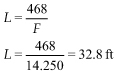
Note: The 0.8-ft part of this calculated length can be converted to inches by multiplying by 12:
0.8 × 12 = 9.6 in
Each leg of the vertical dipole in this example is one half of the calculated length, or
![]()
The vertical dipole antenna is used in many locations where it is impossible to properly mount a horizontal dipole or where a roof- or mast-mounted antenna is impossible to install because of logistics, a hostile landlord, or a homeowners’ association. Some row house and town house dwellers, for example, have been successful with the vertical dipole.
As a general rule, it is wise to try to dress the feed-line away from a dipole at right angles for as much of the feedline length as possible. The primary purpose of this is to avoid unbalancing the pattern of the dipole as well as the currents in the two sides of the transmission line. Unfortunately, any dipole for the HF bands is likely close enough to earth ground or other structural grounds that it already has been compromised.
A coaxial vertical is similar to the vertical dipole (and, in fact, it can be argued that it is a form of vertical dipole) in that it uses a pair of vertical radiator elements. Such an antenna is an extreme case of imbalance because the feedline comes away from the dipole completely in line with it! In this antenna the radiating element that is closer to the ground is coaxial with the transmission line as shown in Fig. 9.2. The use of a transmission line choke immediately beneath the coaxial sleeve will minimize the tendency of the feedline to act as if it were part of the antenna. One form of choke consists of an appropriate number of turns of the coaxial cable looped through one or more ferrite cores of the right material for the frequency involved.

FIGURE 9.2 Coaxial vertical dipole.
The coaxial vertical antenna was once popular with CB operators. In some cases, you can find hardware from these antennas at hamfests or on the used equipment Web sites, and the pieces can be modified for amateur radio use. For use on 10 m, it is a simple matter to cut the 11-m CB antenna for operation on a slightly higher frequency. Conversion for bands below 27 MHz is a little more difficult; most likely only the insulator and mounting assembly are salvageable. Keep in mind, however, that adjacent sizes of 0.058-in-thick aluminum tubing are designed such that the inside diameter (ID) of the larger piece is a slip-fit for the outside diameter (OD) of the smaller piece. You can, therefore, connect adjacent sizes of aluminum tubing together without the need for special couplers, etc. With that in mind, salvaged insulator assemblies can be cut off with just 6 to 10 in of the former radiator and sleeve, and new radiators can be created from telescoped tubing sections.
Grounded Vertical Monopole
The vertical dipole is a perfectly fine antenna, and it has formed the basis for many VHF and UHF broadcast antennas for decades. The reader can build it by using exactly the same dimensions as required for the horizontal dipole of Chap. 6. Its “real life” pattern is as shown in Fig. 9.3 as long as it is kept far (many wavelengths) from conducting objects with dimensions comparable to, or larger than, itself. That turns out to be fairly easy (for fixed stations, at least) at VHF and UHF frequencies, and not so easy at MF, HF, and microwave frequencies.

FIGURE 9.3 Vertical antenna radiation pattern.
It is, in fact, the mechanical difficulty of keeping vertical dipoles far from conducting surfaces that makes the grounded quarter-wave vertical so popular. To suspend a vertical dipole for 80 m, for instance, above the earth requires a support more than 150 ft high! And just bringing the transmission line away from the center of the dipole at right angles would present a completely separate challenge.
We saw in Chap. 5 (“Antenna Arrays and Array Gain”) that we can use the earth beneath us as a substitute for one side of a dipole. So, as the saying goes, “If you can’t beat ’em, join ’em!” Over the range of frequencies where we would have to incur tremendous cost and effort to lift a vertical dipole into the air high enough to avoid unbalanced currents in the two sides, we typically choose to use a quarter-wave monopole operated against the ground beneath.
For the MF and lower HF bands (up through perhaps 5 MHz or so), the simplest approach is to mount the vertical on the earth’s surface. For still higher frequencies, lifting the vertical into the air (to get above any nearby obstructions) works well as long as we also lift an artificial ground plane—consisting of a finite number of (usually equally spaced) radials—with it.
The equivalence of grounded λ/4 verticals to λ/2 vertical dipoles is easily seen if you think of the bottom half of the original vertical dipole as being made of stranded wire. Starting with the dipole, unwrap the strands of the lower wire all the way back to the center insulator and spread them out horizontally, equally spaced around a circle. You have created a ground-plane antenna. Next, take each of the strands and with a very sharp (imaginary) knife, slice it into hundreds of thinner strands. Now spread all of those out equally, as well. Ultimately, you will have a perfectly conducting ground underneath your λ/4 vertical.
Figure 9.4A shows the basic geometry of the vertical monopole antenna. Here a source of RF is applied at the base of a radiator of length L. Although most commonly encountered verticals are a quarter-wavelength (L = λ/4) long, that length is not the only permissible length. For now, however, we will limit our discussion to λ/4 verticals.

FIGURE 9.4A Basic vertical monopole.
Figure 9.4B shows the current and voltage distribution in a quarter-wavelength vertical. Like the half-wave dipole, the λ/4 vertical is fed at a current node, so the feedpoint impedance is at a minimum—typically less than 37 Ω, depending upon nearby objects, diameter of the radiating element, and other factors.

FIGURE 9.4B Current and voltage distribution along λ/4 vertical.
Figures 9.4C and 9.4D show the two configurations previously discussed for a λ/4 HF vertical antenna. In Fig. 9.4C the radiator element is mounted at ground level but electrically insulated from ground and fed with 52-Ω coaxial cable. The inner conductor of the coaxial cable is connected to the radiator element, while the cable shield is connected to ground at the base of the vertical. For a λ/4 radiator, the feedpoint impedance will be lower than 52 Ω, but in most cases, the resulting voltage standing wave ratio (VSWR) is an acceptable tradeoff for simplicity and allows elimination of a matching network or ATU. If the antenna has a feedpoint impedance of 37 Ω, the VSWR will be 52 Ω/37 Ω, or 1.4:1 at the design frequency.

FIGURE 9.4C Simple coaxial-fed vertical antenna.

FIGURE 9.4D Mast-mounted vertical uses radials as a counterpoise ground.
An elevated ground-plane vertical is shown in Fig. 9.4D. This antenna is equally as popular as the ground-mounted quarter-wave vertical, especially on 40 m and above. Amateurs and CB operators find it easy to construct this form of HF antenna because the lightweight vertical can be mounted at a reasonable height (15 to 60 ft) using a television antenna slip-up telescoping mast that is reasonably low in cost. As discussed earlier, this antenna replaces the lower half of a vertical dipole with an artificial ground comprised of quarter-wavelength radials.
The radials of a ground-plane vertical antenna are typically installed at some vertical angle between horizontal (0 degrees) and, say, 45 degrees below horizontal. Figure 9.4D is an example of the latter case, showing a ground-plane antenna made with “drooping” radials. Similarly, Fig. 9.4E is an example of a ground-plane vertical having perfectly horizontal radials. Sometimes the feedpoint VSWR of the antenna can be improved by adjusting the degree of “droop” in the vertical’s radials.

FIGURE 9.4E Ground-plane vertical antenna.
Unlike ground-mounted verticals, the “ground plane” formed by the radials of Fig. 9.4E does not preclude the existence of a far E-field below the horizontal plane of the radials, as suggested by the (solid line) pattern in the figure.
Non-Quarter-Wavelength Vertical Monopoles
If now we gradually increase the length of our grounded monopole, we observe the same flattening of the doughnut shape as we saw with the dipoles of Chap. 6. Lengthening the monopole beyond λ/4 results in additional RF energy in the low-angle main lobe of the pattern, in exchange for reduced radiation at higher elevation angles. Figure 9.5A shows the approximate patterns for vertical monopoles of three different lengths: λ/4, λ/2, and ![]() λ. Note that the main lobe of the quarter-wavelength antenna has reasonable gain over the widest range of elevation angles, but also the lowest maximum gain of the three cases. The
λ. Note that the main lobe of the quarter-wavelength antenna has reasonable gain over the widest range of elevation angles, but also the lowest maximum gain of the three cases. The ![]() -wavelength antenna, which is the grounded monopole equivalent of the extended double Zepp (EDZ), enjoys both the lowest angle of radiation and the highest maximum gain.
-wavelength antenna, which is the grounded monopole equivalent of the extended double Zepp (EDZ), enjoys both the lowest angle of radiation and the highest maximum gain.

FIGURE 9.5A Vertical radiation pattern versus a function of element length over perfect ground.
The patterns shown in Fig. 9.5A assume a perfectly conducting ground surrounding the antenna. The effect of real-earth ground losses is to eliminate any hint of the radiated field at distant receiving sites for elevation angles near the horizon (Fig. 9.5B).

FIGURE 9.5B Accounting for ground losses over real earth.
The feedpoint impedance of a grounded monopole is a function of the length of the radiator. For the standard quarter-wavelength antenna over perfect ground, the feedpoint radiation resistance is a maximum of 37 Ω (i.e., one half that of a λ/2 dipole), with only a very small reactance component. Figure 9.6A plots the reactive and resistive components of the vertical monopole’s feedpoint impedance for radiator lengths from 60 degrees to 120 degrees, while Fig. 9.6B shows the radiation resistance for antennas shorter than λ/6 (90 degrees corresponds to λ/4, so 60 degrees is for a λ/6 radiator).

FIGURE 9.6A Antenna impedance as a function of antenna length.

FIGURE 9.6B Radiation resistance as a function of antenna length.
Note that the radiation resistance for such short antennas is extremely small. For example, a monopole that is 30 degrees long (30/360 = 0.083 λ) has a resistance of approximately 3 Ω. General practice for such antennas is to use a broadband impedance-matching transformer to raise the impedance of such antennas to a higher value (Fig. 9.7), but the biggest problem with such low-radiation resistances is that it is extremely difficult to avoid dissipating most of the transmitter power in lossy grounds, matching network components, and the connections themselves—just ask any serious user of HF mobile equipment!

FIGURE 9.7 Impedance matching through broadband transformer.
Ground Systems for the Grounded Monopole
Earlier in this chapter, we discussed how the vertical antenna radiates equally well in all (azimuthal) directions. Over the years, some wags have said the vertical radiates equally poorly in all directions. Which of these opinions is correct?
In fact, either can be true. The secret of success is this: The grounded vertical monopole antenna works well only when placed over a good ground system. (This comment does not apply to a vertical dipole in free space, many wavelengths away from the nearest conductors.) As we discussed earlier, in a ground-mounted vertical the ground system provides an electrical “return” for antenna currents; it is the replacement for the “other” half of the dipole. To the extent that the ground return is “lossy” or incomplete in its coverage of the radiation field of the vertical, a significant ground loss resistance is added to the total resistance seen by the RF energy delivered to the antenna terminals by the transmitter and feedline. If drawn schematically, ground losses and antenna radiation resistance are in series and, hence, the transmitter output power is divided between the radiation resistance of the antenna and the loss resistance of the ground return system. With radiation resistances in the 2- to 37-Ω range, it does not take much loss resistance to steal half or more of your output power!
Ground return loss is one of the primary reasons mobile installations generally do not get out as well as home station antennas. Because mobile whips (usually operated as grounded verticals) are so much shorter than a quarter-wavelength, their input impedance is very low—usually just a few ohms, at best.
The usual way to provide a good ground for a ground-mounted vertical is to use a system of radials such as those shown in Fig. 9.8. (We will take up elevated ground-plane antennas shortly.) There we see (by looking down from directly above) 16 radials equally spaced to cover the full circle around the antenna. At one time it was commonly understood that each radial was to be a quarter-wavelength, where L (feet) = 246/F (MHz). In truth, radials in direct contact with the ground are sufficiently detuned from their free-space characteristics that an exact length is not at all important. Instead, what is important is that enough radials are installed that their far ends are typically no more than 0.05 λ apart. A little thought will lead to the counterintuitive realization that the shorter your radials are, the fewer of them you need!

FIGURE 9.8 Comprehensive ground system for vertical antenna.
And this is, in fact, true. However, it is also true that the shorter your radials are, the less efficient your ground system will be and the higher your ground resistance losses will be. The basic point being made is this: If you have a fixed amount of wire to apply to your system of radials, a few long radials are not as helpful as a greater number of shorter ones. Stated yet another way, it’s better to have longer radials than shorter ones, but if you can only have shorter ones, you don’t need as many before you will have maxed out the performance gains you can accomplish by adding more radials.
A little math will show that designing your radial system such that radial tips are no more than 0.05 λ apart leads to the following relationship:
N (number of radials) = L (in wavelengths) × 128/λ
Thus, for quarter-wavelength radials, N is about 32. There is nothing magic or abrupt, of course, about the 0.05 λ figure; increasing the spacing from 0.05 λ to 0.10 λ, for instance, simply means a slight increase in ground system losses and a corresponding slight decrease in signal strength at the distant receiving station in return for needing to install half as many radials.
There is also nothing magic about making all the radials equal in length. If you are boxed in by property boundaries, a city lot, or structures that get in the way, simply do the best you can. Radials are important to the efficient operation of verticals, but many different compromise geometries can lead to equally excellent results. Over the past two decades, one of the authors has had a commanding signal on 160 m from two different homes with highly lopsided radial fields of between 16 and 24 radials.
It is also true that the taller the vertical, the longer the radials should be for optimum antenna system efficiency. That is because a taller vertical tends to put return currents into the earth at a greater distance from its base than a shorter vertical does. Again, as the radials are lengthened, the number of them should increase. A “safe” rule of thumb is that your radials should be approximately the same length as your vertical’s physical height.
Probably the most important thing to keep in mind is that transmitter output power headed for the antenna actually gets split, or “used up”, in three ways: feedline losses, antenna and ground system losses, and antenna radiation resistance. Of those, only power dissipated in the antenna radiation resistance contributes to the received signal strength far away. How much power is lost in either of the other two categories is determined with Ohm’s law calculations on a simple resistive divider. The lower the radiation resistance of the antenna, the more attention that should be paid to feedline losses and losses in the ground system. Thus, a radial field used in conjunction with a short transmitting vertical (less than λ/4 tall) requires much more wire than one for a full-size λ/4 or taller monopole if the radiation efficiencies of the two antennas are to be comparable.
Prior to World War II, scientists and engineers performed a series of tests on radial fields for AM broadcast stations. They concluded that anything more extensive than a radial field consisting of 120 quarter-wave radials provided insignificant improvements to radiation efficiency and signal strength. Figure 9.9 is typical of the kind of information that these experiments provided. These test results have formed the basis of much folklore over the years and only recently have new experiments and new reports clarified matters. Today we know that a system of 50 to 60 radials is more than plenty for a quarter-wave ground-mounted vertical in virtually any application, and that the exact length of radials on or in the ground is immaterial.

FIGURE 9.9 Method for connecting many radials together.
One of the least important characteristics of radials is wire size. Antenna return currents are split among the many radials, and the conductivity of even tiny wire sizes is far superior to that of all known soils. Bigger issues are survivability, mechanical strength, and visibility. Wires laid on the ground or on grass are ultimately subjected to a variety of stresses, whether from being stepped on or tripped over, or after easing their way into the sod. Some terrains do not lend themselves to burial techniques, and highly visible insulation may be important to prevent unsuspecting visitors from tripping over them.
CAUTION If you decide to use an aboveground radial system, be sure to include measures to prevent people from tripping over it or (if it is an elevated system) running into it. Depending on the law where you live, there can be liability implications when a visitor gets injured, even if that person is an intruder or trespasser.
The return currents in radials result from displacement currents flowing in the capacitor formed by the vertical element and the ground system. Displacement currents (see Chap. 2) are RF alternating currents that do not require a conducting medium for their existence. Consequently, radials can be either insulated or bare, although bare metals used outdoors will develop an oxide insulating layer on them sooner than insulated conductors. Radials can be copper or aluminum. Many amateurs have formed their radial fields out of scrap wiring from multiple sources, while others have managed to create additional wire by separating multiconductor cable into individual strands. If buying wire new, it’s hard to beat the price of 500- or 1000-ft spools of interior house wiring at the large discount home supply stores.
Because of the orientation of the electromagnetic fields around the vertical, only the ground resistance along radial lines from the base of the vertical is important. That is to say, there is little merit to connecting the tips of the radials together or adding other nonradial wire interconnections to the basic radial system. The same is true of ground rods, which, in and of themselves, are virtually useless in improving the performance of grounded verticals.
Typically, all radials are connected together at the base of the antenna, and the ground side of the transmission line is connected to this system. When installing radials, try not to put them too far below the surface of your soil; the farther beneath the surface they are, the less effective they become.
While a radial system can be designed to serve as part of your lightning protection and grounding system (Chap. 30), it does not have to be. Although conventional solder connections are eventually destroyed outdoors and will vaporize in the path of a lightning strike, as long as it’s understood they’re not “forever”, there’s nothing wrong with soldering your copper radials to a copper bussbar or flexible plumber’s tubing circling the base of your vertical. (See Fig. 9.10.)

FIGURE 9.10 Field strength versus number of radials.
Extremely important, however, is to avoid putting copper in direct contact with the legs or cross-braces of your galvanized tower if that is what you are using for your vertical. Appropriate clamps can often be obtained at electrical supply houses. In any event, sliding a sheet of thin stainless steel between any copper and the tower leg will eliminate the problem.
Some amateurs prefer to place a copper wire screen at the center of the radial system. The minimum size of this screen for it to be useful is a function of the vertical’s operating frequency range and the height of the vertical element. A possible concern is the creation of rectifying junctions after extended exposure to the elements at each location where two wires in the screen cross.
Feeding the Ground-Mounted Vertical
The feedpoint resistance of a vertical monopole over perfect ground is one-half that of a dipole in free space. Thus, the input impedance of a λ/4 vertical radiator fed against ground is about 37 Ω. For many applications this is close enough to 52 Ω that no further matching is required, and 52-Ω coaxial cable or hard line can be connected directly to the antenna. If minimizing the standing wave ratio (SWR) on the transmission line is important, the matching network can be a commercially available antenna coupler (protected from the weather by some form of housing) or a simple L-network. In either case, the purpose of the coupler or network is to raise the resistive part of the impedance seen by the transmission line to 50 or 75 Ω while simultaneously canceling out the reactive portion of the antenna impedance. In general, the coupler settings or L-network fixed component values will be suitable for only a narrow range of frequencies; typically, the values or settings used for, say, 40 m will not be useful on any other amateur bands. Of course, direct feed implies that the base of the vertical is not in electrical contact with the ground system beneath it. This is often called series feed.
Alternatively, the base of the vertical radiator can be tied to ground and the resulting antenna fed through a tap point on the vertical section some distance above the base. Known as shunt feed, many forms of this have been devised and are discussed in detail elsewhere in this book. In the shunt-feed arrangement, the connection partway up the vertical element functions much like an autotransformer. This is best visualized by observing that since the tip of a quarter-wave vertical is a high-impedance point (no current, high voltage) and the base is a low-impedance point (high current, low voltage), the impedance observed along the vertical element gradually increases as one moves the observation point from its base up toward its tip. One advantage of this approach is that the shunt-feed network generally allows for close matching of the feedpoint impedance to an arbitrary transmission line impedance.
There are three methods of shunt-feeding a grounded vertical antenna in common use today: delta, gamma, and omega. In general, shunt feed is useful when the resistive component of the antenna impedance on the centerline of a balanced element or the junction of the vertical element and ground is significantly lower than the characteristic impedance of the transmission line feeding it.
The delta feed system is shown in Fig. 9.11A. In this case, a taut feed wire is connected between a point on the antenna, which represents a specific impedance on the antenna, and an antenna tuner. At one time, this method of feed was common on AM broadcast antennas. Although you would think that the sloping feed wire would distort the pattern, that is not the case; any such distortion is minimal.
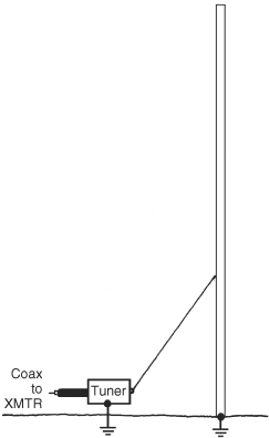
FIGURE 9.11A Delta-fed grounded vertical.
The gamma feed system is shown in Fig. 9.11B. This method is commonly used by amateurs to feed Yagi beam antennas, so it is quite familiar to many in the amateur radio world. In effect, the gamma match and its cousins use distributed components to accomplish the same impedance-matching functions a coupler or L-network does in the series-feed case. The two critical dimensions for a gamma match are the distance from the base or centerline of the antenna to the tap point on the antenna (i.e., the active length of the gamma rod) and the spacing of the gamma rod away from the antenna element. The lower end of the gamma rod is not grounded; rather, it is connected to the hot side of the transmission line. It is important that the rod not be anywhere near a quarter-wavelength, or it would become a vertical antenna in its own right, and in fact would resemble the J-pole antenna.

FIGURE 9.11B Gamma-fed grounded vertical.
One advantage of the gamma match and other shunt-feed techniques is that the vertical antenna element retains a direct connection to ground, providing superior static discharge during and ahead of approaching thunderstorms. This is especially useful on the lower amateur frequencies, where verticals are often built using triangular guyed tower sections and it is less expensive to construct the tower with a direct electrical connection (through the tower legs) to ground.
The biggest disadvantage of the gamma matched vertical is that it is much more difficult to initially adjust because the gamma rod tap point may be well beyond the user’s reach—especially on the lower bands. A secondary disadvantage is that some methods of feed for multielement phased arrays of verticals use current-forcing techniques that are easier to control with the series feed.
Unless the user has the ability to adjust not only the gamma rod spacing and length but also the overall length of the vertical element, the gamma match may require a simple matching network between the base of the antenna and the transmission line. In the easiest cases, a single series capacitor or inductor between the base of the gamma rod and the hot side of the feedline may be all that is needed to obtain a satisfactory match and SWR. More generally, an omega match (Fig. 9.11C) can be inserted, although the user may need to experiment with which side of the series capacitor (CS) the hot end of the gamma capacitor (CG) should attach to.

FIGURE 9.11C Omega-fed grounded vertical.
Chapter 18 (“Antennas for 160 Meters”) includes details of a gamma match for a top-loaded tower on 160 m. In some difficult cases, when the tower length or available loading is not ideal, an omega match feed system (shown in Fig. 9.11C) may be necessary. The omega match adds a shunt capacitor to the basic gamma match.
As the radiating element of a vertical monopole increases beyond λ/4, both the resistance and the reactance seen at the series feedpoint increase, as well. Thus, for any significant increase in the length of the vertical radiator, direct matching to commonly available transmission lines will result in increased SWR on the transmission line, so some form of matching network or ATU should be employed. Again, an alternative is to directly ground the base of the radiator and use some form of shunt-feed network to accomplish the proper match.
The base impedance of a ![]() -wavelength antenna is about 1600 Ω—certainly not an acceptable match for anything but a custom-designed transmission line. So some form of impedance matching is needed.
-wavelength antenna is about 1600 Ω—certainly not an acceptable match for anything but a custom-designed transmission line. So some form of impedance matching is needed.
For a single-band ![]() λ antenna, one option is to use a form of stub matching employing unbalanced coaxial cable, such as shown in Fig. 9.12. The lengths are given by
λ antenna, one option is to use a form of stub matching employing unbalanced coaxial cable, such as shown in Fig. 9.12. The lengths are given by

FIGURE 9.12 Q-section for match feedpoint impedance to line.
![]()
or
![]()
and
![]()
or
![]()
Elevated Ground-Plane Antenna
There are three key differences between a ground-mounted vertical and an elevated ground-plane vertical:
• Radials located some distance above ground must be treated as resonant elements.
• Fewer radials are needed to ensure that most of the transmitter power is delivered to the radiating element instead of being dissipated in lossy earth.
• An elevated GP vertical may have fewer nearby obstacles (e.g., trees and buildings) and thus enjoy a cleaner shot at low elevation angles.
Once the base of an elevated ground-plane vertical is raised above a certain height (many consider λ/8 a reasonable minimum), its radials act less like long, skinny capacitors and more like the other half of a vertical dipole. As such, it is important for maximum radiation plus ease of matching that their lengths to be approximately λ/4 at the operating frequency, although the exact length will vary somewhat with radial “droop”—the vertical angle at which the radials come away from the base of the monopole.
However, the farther away the lossy earth is from these elevated radials, the less effect it has and the easier it is to capture the bulk of the return currents of the vertical radiating element in a small number of radials. Recent experiments based on detailed modeling using NEC-4 (see Chap. 25) indicate that somewhere between two and eight radials per band is quite adequate for elevated antennas, although unless at least three equispaced radials are used, there will be some variation in field strength with azimuth (compass heading). The improvement in radiated field characteristics for more than three or four radials is quite subtle, however, as long as the GP antenna is kept at least λ/8 off the ground. Models of a λ/4 antenna show little difference between horizontal and drooping radials other than to raise the feedpoint impedance from 25 to 40 Ω.
Keep in mind that these discussions of height above earth ground refer to the height of the electrical ground, not the sod. Depending upon ground conductivity and ground-water content, the effective height of earth ground may lie some distance beneath the surface. The actual depth is best found from experimentation and may, unfortunately, vary with precipitation and with the season—especially if the ground freezes and/or the local water table changes greatly.
Vertical versus Horizontal Polarization
A question frequently asked is: “Would I be better off putting up a horizontal dipole or a vertical?” As usual, the answer is: “It depends.” Here are some factors often found to be helpful in arriving at an answer:
• Is there a “convention” regarding antenna orientation (polarization)? Usually because of historical patterns of usage that have evolved, certain groups have standardized on specific polarizations. The 11-m citizens band, for instance, uses vertical polarization because of the high percentage of vehicular mobile users. As a result, almost all house- or tower-mounted antennas—even multielement Yagis and quads—for 27 MHz are vertically polarized. The same is true for most FM mobile and repeater operation on 2 m and above, whereas weak signal SSB or CW DXing on those bands is accomplished with long-boom, high-gain Yagis employing horizontal polarization. Almost all broadcast television receivers were originally located in residential dwellings, so that service began with horizontal polarization as the standard, today’s video-equipped RVs and limousines notwithstanding. Today some FM broadcasting is done with the transmitted signal split between horizontal and vertical polarization, in recognition of the fact that substantial numbers of antennas in both “flavors” are in use.
• What frequencies do you wish to use? What is your objective for a particular antenna? On the HF bands there is generally a 6-dB ground reflection advantage at each end of the path at higher elevation angles for horizontal antennas, but below about 10 MHz verticals often outperform all but the highest dipoles and beams at low radiation angles. Otherwise, the source polarization is immaterial for skip propagation because the ionosphere tends to randomly rotate the polarization of waves passing through it regardless of what was delivered to it. If you are an inveterate DXer, you will most likely enjoy more success on the MF and lower HF bands with a vertical than with a dipole, but if your principal operating activity is a regional or local network of friends, a low horizontal dipole or loop may be your best choice.
• Are you bothered by local noise sources, and, if so, do they favor one polarization over the other? If you can effect an improvement in received signal-to-noise ratio (SNR) through the proper choice of polarization, that may be the single most important factor for your specific installation.
• What space or support limitations do you have? A treeless residential backyard may be better suited for an 80-m ground-mounted λ/4 vertical than for a λ/2 dipole, while some college dormitory residents have had great success with a simple dipole or end-fed longwire stretched from rooftop to rooftop across the courtyard below.
Perhaps the best answer to this question is: “Put up at least one of each!” Some years ago the author had both a dipole and an elevated ground-plane vertical for 40 m behind his house. In actual use, there were “dipole nights” and “vertical nights” on 40, with received signal strength differences on transatlantic paths shifting back and forth between the two antennas from night to night by as much as 20 dB! No one antenna can do it all; if you have the space and the time to put up two or more antennas.
Supporting the Vertical Antenna
Verticals for frequencies below about 5 MHz are substantial structures; their support requirements are akin to those of 60-ft or greater towers. Therefore, information on supporting verticals for the MF and lower HF bands is found in Chap. 29 (“Towers”).
Above 5 MHz, supporting a λ/4 vertical is a much simpler task. For these antennas, the techniques of Chap. 28 (“Supports for Wires and Verticals”) are typical.