CHAPTER 17
Emergency and Portable Antennas
Some time ago, one of the authors met an interesting character at a convention. This man was a medical doctor, working as a medical missionary at a relief station in Sudan. Because of his unique business address, he was a veritable fount of knowledge regarding the use of mobile and portable antennas for communications from the boondocks. His bona fides for this included the fact that he was licensed to operate not only on the amateur radio bands but as a land mobile (or point-to-point) station in the 6.2-MHz band. The desert where he traveled is among the worst in the world, and the path he euphemistically called a “road” was frequently littered with camel corpses because of the brutal environment. The doctor’s organization required him to check in twice daily on 6.2 MHz or a backup frequency. If he missed two check-ins in a row, then the search-and-rescue planes would be sent out. As a result of his unique “house calls”, he did a lot of mobile and portable operating in the lower-HF region of the spectrum. With that as background, the problem he posed to the author was this: How do you reliably get through the QRM and tropical QRN with only 200 W PEP and a standard loaded mobile antenna?
Another fellow worked in Alaska for a government agency. He faced many of the same problems as the doctor in Sudan, but at temperatures nearly 100 degrees colder. He frequently took his 100W mobile rig into the boondocks with him in a four-wheel-drive vehicle. Again, the same question: With only 100 W into a low-efficiency loaded mobile antenna, how does one reliably cut through the interference to be heard back at the homestead?
Suppose an earthquake or a hurricane strikes your community. Antenna supports collapse, tribanders become tangled masses of aluminum tubing, dipoles are snarled globs of #14 copper wire, and the rig and linear amplifier are smashed under the rubble of one corner of your house. All that remains is the 100W HF rig in your car. How do you reliably establish communications in “kilowatt alley” with a 100W mobile transceiver driving an inductively loaded mobile whip? Of course, you always got through one way or another before, but now communications are not for fun—they are deadly serious. Somehow, the distant problems of a Sudanese missionary doctor and an Alaskan government forester seem much closer to home.
For these operators, the ability to communicate—to “get through”—often means life or death for someone. Given the inefficiency of the loaded whips typically used as mobile antennas in the low-HF region, the low power levels generally found in mobile rigs, and the crowded conditions on the 80-, 75-, and 40-m bands, it becomes a matter of more than academic interest how they might increase the signal strength from their portable (or mobile) emergency station. Anything they can do, easily and cheaply, to improve their signal is like having money in the bank. Fortunately, there are several tricks of the trade that will help.
In cases of emergencies on most highways, we are likely to be in range of some repeater, so we would use a VHF band (probably 2 m) to contact police or other emergency services—perhaps through manual assistance from another ham on the repeater, perhaps through a repeater autopatch. In fact, with the wide availability of repeaters around the country it behooves any amateur backpacking or four-wheeling into remote areas to be familiar with nearby repeater locations and frequencies.
As we saw in the preceding chapter, the HF mobile configuration is inefficient by its nature, and little can be done to improve matters . . . at least while remaining capable of being operated “in motion”. But if we recognize that the operator needing emergency or urgent communications is most likely not driving down the road somewhere but is stopped in a remote location and needs to contact someone outside his local area, we can improve the performance of the “mobile” station by employing techniques not available to the mobile operator who is “in motion”.
Most amateurs with experience in mobile HF operation will attest to the need to enhance their signal if they are to be effective in providing emergency communications. Setting aside for the moment the issue of output power levels, mobile radiation efficiencies are simply too poor to consistently compete with the larger and better installations found at most home and fixed (or base) stations. There are three primary reasons for this:
• The radiating portion of virtually every mobile HF antenna is substantially less than λ/4 in length, making its radiation resistance extremely low and difficult to match with low losses.
• Below 2 m, most vehicle bodies make very poor RF grounds, thus further compounding the problem by dissipating a greater portion of the transmitter output power in the resistance of the lossy ground.
• In most emergency situations, the preferred coverage distance is considered “close in” for HF propagation modes, even though it may be beyond the reach of the nearest 2-m repeaters. The use of a conventional mobile antenna mounted on the vehicle (in situ) results in a vertically polarized signal with maximum amplitude at relatively low wave angles, while ionospheric propagation modes for the distances involved overwhelmingly favor an antenna that puts most of its energy into the higher wave angles. This is a perfect match for a low, horizontally polarized radiator.
Let’s discuss each of these limitations in more detail, with the intention of identifying simple workarounds for the temporary situations that most emergency and portable operations imply. Keep in mind that throughout the discussion we are assuming that the vehicle and the mobile gear it is carrying are in a fixed location for the duration of the emergency or portable activity.
Improving Radiator Efficiency
If at all possible, the smartest solution to the first component of loss is to replace the mobile antenna with a longer, more efficient, stowable antenna that can be brought out and erected when needed. In real-world antenna systems, efficiency of radiation increases dramatically as the length of the radiator approaches λ/4. One candidate is a surplus military HF whip antenna. Intended for jeeps and communications trucks, these antenna/tuner combinations are collapsible and are as efficient as any on the market. Alternatively, a quarter-wave length of wire (or, with a suitable antenna tuner, anything longer than the mobile whip) can be attached where the mobile whip was located previously. Carrying a ball of twine attached to a baseball with a small-diameter hole drilled through its center might not be a bad idea. It should be possible to get one end of the antenna wire up in the air perhaps 20 or 25 ft, draped over a tree branch, with such a rig. If necessary, arrange to support the far end of the wire a little distance from the rear of the vehicle so that the lack of height is made up for by the added horizontal distance the wire is covering. (Move the vehicle, if necessary.) This creates a sloping vertical, which is not all that bad an antenna, believe it or not.
Reducing Ground Losses
Even for frequencies as high as 6 m the typical vehicle body is not large enough to provide an adequate ground plane. A better solution is to provide a counterpoise or elevated ground plane. As we saw in the chapter on verticals (Chap. 9), the basis for this recommendation is that a vertical monopole, such as a mobile whip, is really only half an antenna. The other half is distributed throughout the ground return for the antenna, and a failure to provide an adequate ground system is equivalent to further compromising the antenna itself.
Figure 17.1A is the schematic representation of a proposed way to enhance the ground return efficiency for a mobile whip used in a portable or emergency (i.e., vehicle not in motion) situation. At its minimum it consists of the addition of three or four radials, each λ/4 in length on the band(s) of interest and spread as equally as possible around the full 360-degree compass rose. Ideally, such a ground-plane antenna should be mounted λ/8 or higher with some kind of additional support, but the degradation in performance is gradual as the height becomes progressively lower, so you do the best you can with what you have.

FIGURE 17.1A Radials can enhance a basic mobile antenna system at a fixed location.
When selecting radial wires, the primary requirement is that they be strong enough to withstand the mechanical rigors of being repeatedly installed, taken down, coiled up, and stored. Current-handling capability in radials is seldom an issue, regardless of wire diameter. A number of suppliers of antennas and accessories sell spools of bare #18 wire for radials; a 500-ft spool takes up little space in a car trunk. For many portable and emergency setups, however, insulated wire may be best because there may be a need to drape one or more radials across a metallic object of some sort; clearly, direct metal-to-metal contact with other objects would be undesirable and could cause extra noise in the receiver. For 40 m, four λ/4 radials total 132 ft. Allowing some extra wire for connections to the base of the whip and for attaching to rope or twine at the other end, 150 ft of #14 wire is all that is needed.
Figure 17.1B shows a workable system that will further improve the performance of a mobile rig in stationary situations. The mobile antenna uses the normal base mount attached to the rear quarter-panel of the car adjacent to the trunk lid. An all-metal grounding-type binding post is installed through an extra hole drilled in the base insulator (see Fig. 17.1C). Radials for portable operation are attached at this point. The binding post should be sized to easily accommodate three or four #18 radials. In a pinch, additional radials can be attached to the base indirectly by connecting them to the top of one or more of the radials already on the binding post.

FIGURE 17.1B Multiple radials are even better.
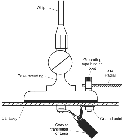
FIGURE 17.1C Connection of radials to mobile antenna.
Selecting the Right Polarization
The final component of improving the HF signal from an emergency or portable station setup is to match antenna polarization to the intended coverage distance(s) and the surrounding ground characteristics. Although there is occasionally a reason (most often for low-band operation by DXpeditions in major amateur radio competitive events) to use vertical polarization for portable operation on the lower HF bands, by far the most likely scenarios dictate the use of a horizontally polarized antenna.
Putting up a dipole is an often overlooked approach when operating portable. In addition to increased radiation at high wave angles, this eliminates the need for ground radials and may cut the required amount of wire in half.
The biggest impediment to erecting a dipole sufficiently high in the air to be useful is the number and spacing of suitable available supports. Trees, flagpoles (but not utility poles), roofs of buildings, and upstairs windows can all be candidates. Depending on the distances to be covered, a height of 30 or 35 ft for an 80-m dipole can be quite useful.
Because of the low power level involved, the dipole can be fed with lightweight RG-58 or RG-8X coaxial cable. Of course, open-wire line (OWL) is an excellent companion to a dipole, but most will find it easier to keep a stored roll of coaxial cable in good working order between emergencies or portable “expeditions” than to stow a spool of true OWL.
In a pinch, zip cord or lamp cord makes an easily obtainable feedline; measurements on zip cord some years ago indicated a characteristic impedance of about 72. However, the losses can become excessive on the higher bands. In a worst-case scenario, lengths of rotor cable, telephone cable, or Cat 5 or Cat 6 Ethernet cable can be pressed into service!
Figure 17.2 shows the common dipole and the normal equation for determining approximate length. Typically it is cut “long” and then trimmed until the VSWR drops to its lowest point, a nicety that might not seem altogether important in an emergency. One or both ends of the dipole must be supported on trees, masts, or some other elevated structure.

If only a single high support is available to use, a sloping dipole or an inverted-vee can be substituted for the dipole. For the antenna of Fig. 17.3, assume as a starting point for dimensions that the length of each leg is 6 percent longer than would be obtained by using the dipole formula of Fig. 17.2.
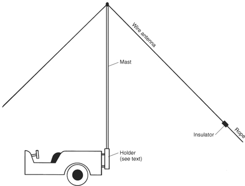
FIGURE 17.3 Portable inverted-vee antenna.
A final approach is to combine the vertical with the horizontal and run a random-length wire up as high as you can and then horizontally as far as you can. A total of 140 to 160 ft makes a pretty good run for 160 m, and a total length of 70 to 100 ft should work well for 80 m. This is an inverted-L, which is a very efficient cousin to a conventional λ/4 monopole; its radiation and matching characteristics are covered in detail in Chap. 18, but its advantage here is that it’s very simple to erect, and it provides a mix of high-angle and low-angle radiation from a single antenna. Note: For proper operation, the inverted-L must have radials, a counterpoise, or a tuned RF ground (see Chap.15) at the feedpoint!
Almost without fail, all of these portable antennas will outperform the basic mobile whip installation. Because the application is both emergency-related and temporary in nature, we can get away with installation and support techniques that would be unthinkable in more permanent installations. But it is absolutely imperative to have an antenna tuner and VSWR monitor to properly set them up.
Temporary Supports
Anyone serious about being prepared for emergency or portable radio operation will very quickly develop an extensive list of “must have” items. The extent of the list will depend on the magnitude of the planned operation and the conveyance mechanisms available. A list of possible components for a functioning radio station for backpackers will be substantially shorter than one for stowing some gear in a vehicle prior to motoring into the backcountry. Size and weight are major constraints in both cases, but the scale is different.
Probably the single biggest antenna item for portable or emergency use is the antenna support, if required. In many parts of the world, there are trees all around but in other areas, sand or fields are all that is visible for miles around, and some form of temporary mast(s) must be employed.
Where trees are available, use of a bow with suitably modified arrows may be the best way to get support lines up high. For nearly 30 years one of the authors used a “portable” bow that could be broken down into small sections to erect not only temporary dipoles but also all his home station wires that were supported by trees. See Chap. 28 for more information on this and similar techniques.
If trees are not plentiful, various mast alternatives, ranging from extremely heavy (military surplus or steel TV antenna sections) to reasonably light (plastic pipe and fiberglass rods) are available. Your choice is determined primarily by whether you expect to have help erecting the mast and by how much room you have for stowing and transporting it. Also, be aware that some masts consist of telescoping sections that get progressively smaller (and more limber) toward the top. Most masts collapse to 6 or 8 ft in length for transport and stowage, but can be pushed up to heights of 18, 25, 30, 40, or 50 ft, depending upon the type selected. Keep in mind, when shopping for these masts, that the larger models are considerably heavier than shorter models, and they require two or more people to install them. Erecting a 40- or 50-ft telescoping mast is not a one-person job!
Masts made of PVC plastic plumbing pipe are somewhat lighter. If mast sections can be carried on top of the vehicle, then lengths up to 10 ft are available and can be joined together at the site with couplings. If the sections are going to be transported inside the vehicle, be sure to determine the maximum length that will fit before cutting longer sections into smaller ones. Be very careful not to use PVC pipe that is too small, however; PVC pipe is relatively thin walled and can become quite flexible as it is extended in length. Sizes below 1.5-in diameter will not easily stand alone without guying. Nor is PVC pipe particularly self-supporting. While a single 10-ft section might be, two or more sections together will not support themselves plus the weight of any reasonable antenna. Guying will be necessary—either with ropes or on a temporary basis with synthetic (or other water-repellant) twine.
If you plan to erect temporary or portable antennas that represent a heftier downward or sideward pull on the support mast(s)—an 80-m dipole, for instance—and you have a motor vehicle for transportation, you may wish to employ the heavier but more rigid steel TV antenna masts. Available in 5- and 10-ft lengths, these masts are flared on one end and crimped on the other for joining together to form longer lengths. Make sure you procure the mating guy wire rings, too; although not absolutely necessary, they can make the job of putting the antenna up and keeping it up easier.
Over the years the authors have used military and steel TV mast sections many times—especially during Field Day, the annual American Radio Relay League (ARRL) emergency preparedness weekend exercise. The inverted-vee antenna is, of course, a natural for this kind of event, but once one group the author was with mounted a Hustler mobile antenna at the top of a 20-ft mast with four radials; it worked surprisingly well given the low output power (30 W) being used.
Rather than reinventing the wheel, often it’s productive to look around and see how other groups of people are solving similar problems. Certainly one of the first areas to look to is the RVing public. Recreational vehicles have come a long way in recent years; they sport an amazing variety of creature comforts, many of which require interesting and useful add-ons to the basic RV. Extras such as satellite and over-the-air television, side awnings, and the like require the optional addition of supports and support tubing to these vehicles. As a result, a huge aftermarket industry has developed, and many of these dealers and suppliers are likely to have products that can be adapted easily to specific antenna support needs.
Another source of creativity was pointed out to one of the authors by a CB operator some years ago. Surf fishers on the Outer Banks of North Carolina use four-wheel-drive vehicles to get out onto the beach to the surf, where the big sea bass lurk. Welded to either the front or rear bumper attachments of the 4WD vehicles are steel tubes (see Fig. 17.3) used for mounting the very, very long surf casting rods. This particular CB operator had a 20-ft mast, consisting of two 10-ft TV mast sections, mounted in one of the rod holders. At the upper end of the mast was his 11-m ground-plane vertical. The same method of mounting would also support similar amateur HF antennas, inverted-vee dipoles, or even a VHF Yagi or UHF dish.
Given that the antenna installation will be temporary, normally lasting only a few hours or a few days, we need not worry about long-term integrity or the practicality of the installation. Mounting the mast to the back of a four-wheeler or pickup truck with a pair of U-bolts is not terribly practical if you must move the vehicle, but it works nicely if you plan to camp (or are stranded) for a few days.
For lightweight masts located away from the vehicle—up to about 25 ft, say—the support could be an X-shaped base made of 2- × 4-in lumber (Fig. 17.4A), or even a larger Christmas tree stand. Alternatively, a TV antenna rooftop tripod mount (Fig. 17.4B) is easily adapted for use on the ground. None of these three alternatives can be depended upon to provide a safe self-supporting installation, and all of them must be guyed, even if used for only a short period. Again, because of the temporary nature of the installation, aluminum or wooden tent pegs can be used to anchor the guy wires, depending on the soil characteristics in the area. Although they are clearly not appropriate for long-term installations, they should work fine for the short run.

FIGURE 17.4A Wooden antenna stand.

FIGURE 17.4B TV antenna tripod also works in portable situation for HF antenna masts.
Summary
The ideas presented in this chapter are meant to help the reader maximize his/her signal under adverse conditions in the field. While methods of getting antennas up in the air under difficult circumstances are substantially different from those techniques we would normally employ at our home or business, the electromagnetic principles that maximize signal transmission and reception do not change. In particular, remember these key points:
• Try to make horizontal (or inverted-vee) antennas as close to an electrical half-wavelength as possible; don’t rule out the use of traps to allow easier multiband operation in a limited space.
• Try to make any vertical monopoles as close to an electrical quarter-wavelength as you can; if you can get the base of the vertical off the ground, create a groundplane antenna with two or three λ/4 radials on each band to be used. If the vertical must remain ground-mounted, try to put down eight or more radials total, with lengths as long as you can make them, up to a maximum of λ/4 on the lowest frequency of intended use.
• If you have only a single elevated support available, consider either a sloping dipole or an inverted-vee on the lower HF frequencies. Spread the legs of the inverted-vee as far apart as possible.
• Select your antenna to match the type of communications you need. If you are primarily interested in contacting others in your own general area (i.e., within a few hundred miles) on HF, use a horizontal wire. If you’re on a DXpedition to a remote South Sea island, you’ll probably want to use a vertical on the beach.
• Make sure you have a meter for reading both forward and reflected power or, alternatively, VSWR. Most of today’s small HF transceivers have that capability built in. At VHF and UHF, however, it may be necessary to bring along a stand-alone wattmeter or SWR bridge.
• Similarly, make sure you have an antenna tuner for the HF bands—either built into the rig or as a separate accessory. For VHF and UHF ground planes, as well as mobile whips, however, all you may need is an Allen wrench to adjust the top section of the vertical whip.
• Be sure to bring rope, twine, insulators, and short lengths of coax and other cables, with the proper connectors on each end.