CHAPTER 30
Grounding for Safety and Performance
In most radio transmitting or receiving installations there will be four different types of ground systems to consider and implement:
• Grounding for lightning protection
• Grounding for power distribution safety
• Grounding all station equipment together
• Grounding for maximum antenna efficiency
The first three are absolutely necessary; the fourth may be important, depending on the type(s) of antenna(s) in use.
NOTE The single most important message to take away from this chapter is this: A good lightning ground is not necessarily a good radio ground, and neither of them provides a safe power distribution or equipment ground in and of itself. In short, for a proper communications installation, all four types of ground systems must be independently considered, designed, and installed. Nonetheless, in many installations, components of any of these ground systems may well function as components of one or more of the other three systems.
Grounding for Lightning Protection
Although lightning figured prominently in early electricity experiments—especially those conducted (pardon the pun) by Benjamin Franklin—it remains one of the most unpredictable and incompletely understood phenomena in electromagnetics today.
But despite some remaining gaps in our understanding of lightning, the scientific body of knowledge is sufficiently mature today that lightning experts are able to provide valuable guidance to all of us for protection of our lives and our property—usually couched in terms of a statistical “probability”. In other words, predicting exactly what lightning will do is difficult, if not impossible, but predicting what it is likely to do is helpful most of the time. The problem is akin to that of weather prediction—the scope of the system is enormous, and the number of variables not under our control is mind-numbing.
Under the right (or “wrong”, depending on your point of view) conditions, the earth and its atmosphere in localized regions of the globe can form a power supply of virtually infinite energy. Electrical potential differences of millions of volts build up between objects on the earth and particles in the earth’s atmosphere directly above. (Think in terms of an extremely large parallel plate capacitor being charged through a series resistance by an infinite supply voltage, so that there is a time interval associated with how quickly a thunderstorm can “recharge” a given area of a cloud.) At some point, this voltage becomes large enough to jump across air by ionizing or breaking down the air molecules. (A typical breakdown figure is something less than 100,000 V/in of dry air, but the exact voltage depends on the shapes of the two electrodes, and there is much about high-voltage phenomena that is nonlinear.) When there is moisture in the air, the voltage required to ionize the path to earth drops substantially. Any wonder, then, that it is virtually impossible to predict where lightning will strike? Have you ever seen or created a map of humidity versus position in your backyard, for instance? The jagged shape of a lightning bolt is simply the result of the stored energy in our atmospheric system taking the “path of least resistance” . . . literally.
And what could provide less resistance than a wire or a metal tower standing tall in someone’s backyard? The very attributes of antennas and their supports that we value are the same characteristics that make them more likely to be targets of frequent lightning strikes. Similarly, tall trees are frequent targets because they exhibit a finite resistance and are capable of electrical conduction, especially when the sap is running. The old adage is a good one: “In a thunderstorm, seek shelter but don’t stand under tall trees.” To that we can add, “Don’t stand under radio towers and utility poles, either.”
The second characteristic of lightning that we have to deal with is that a typical stroke passes peak currents of thousands of amperes (20,000 A is often cited). The heat generated by such a huge current flowing through even a minuscule resistance is sufficient to blow apart concrete tower bases and vaporize not just solder connections but entire antennas! Thus, in addition to immediate death or permanent disability from the electromagnetic effects of being hit by lightning, there is a comparable risk from proximity to exploding objects, extreme radiated heat, splashes of boiling water (from the ground) or tree sap, and flash fires (from overheated wires in the walls of wood frame dwellings).
There is no known way to totally prevent a lightning strike from coming to your neighborhood. Thus, the first purpose of a ground system for lightning protection is to minimize the damage caused to people and property from a lightning strike that is almost certain to find you someday. To that end, the current professional consensus is to attempt to harmlessly dissipate in the loss resistance of the nearby earth as much of the energy in the lightning bolt as possible. The level to which you, the station owner, can do that is determined by the unique characteristics of your site, your tower and cabling configuration, and your wallet.
Bear in mind that lightning does not know the difference between a tower erected for radio communications and a length of house wiring in the attic of a three-story home. The tower may well be somewhat higher than the attic wiring, but both are ultimately grounded and both are “juicy” targets for a lightning bolt looking for a path to earth ground. If conditions are right (such as the air immediately above the house being of higher humidity than the air near the top of the tower), the house may well be more likely to be hit than the tower.
The usual method for dissipating the energy in a lightning surge is to attempt to spread that energy to a large area of ground surrounding the target tower(s) and antennas. This is done most often by connecting the base of the tower to a set of lightning radials comprised of straight runs of #6 AWG or larger copper wire or flat copper strap with a cross-sectional resistance no greater than that of #6 wire. Soil conditions permitting, each radial should be connected mechanically or with a brazed joint to multiple 8-ft ground rods of the type found at electrical utility suppliers such as Graybar. As shown in Fig. 30.1, the first ground rod on each radial should be one ground rod length (or 8 ft, in this example) from the base of the tower, and all subsequent rods should be 16 ft (i.e., twice the length of the rod) beyond the previous rod. The minimum practical number of radials is probably 4, with 8 to 16 being a better choice. Two or three rods per radial probably constitute a minimum system.

FIGURE 30.1 Tower lightning ground system.
Since the objective of lightning radials is to “dump” the surge currents—whether direct or induced—from the lightning bolt into the soil, there is no reason the radial wires (and the tops of the ground rods) can’t be buried many inches under the surface of the ground. However, as we discuss later, if the lightning radials are to be a part of a ground-mounted vertical antenna’s radial system, they should not be located more than a few inches below the surface, or the ground losses associated with the vertical’s return currents will increase and overall antenna efficiency will suffer. Strange as it may seem, when it comes to lightning surges we want lossy soil but when it comes to radio signals we want lossless soil!
When soil conditions do not allow 8-ft ground rods to be fully pounded in, shorter rods can be used, with some lessening of performance unless the number of radials and rods is increased. As a last resort in very rocky terrain, ground rods can be laid horizontally and buried just under the sod.
Spectral analyses of lightning surges show the bulk of the RF energy to be in the 1-to 3-MHz range. Thus, a key requirement of a lightning ground is that it exhibit a very low impedance to lightning—not just at dc and power line frequencies but up through 3 MHz or more. As a practical construction matter, the radial wires and straps being used to dissipate the energy should have no sharp bends or other sources of excessive inductance. In Chap. 3 we noted that a current flowing in a length of wire creates a magnetic field around the wire and that a large enough current will result in a field so strong as to be able to actually move that wire or neighboring wires. So it should not be surprising that large surge currents in conductors from nearby lightning strokes can create mechanical stresses at sharp bends.
The other important thing to remember is Ohm’s law: V = IR. It does not take very much resistance in a wire or a junction to create extremely high voltage drops (and power dissipation) in the presence of a lightning surge. The heat generated when lightning surges through ground wires and their connections is well above the amount needed to melt any solder you might have available. Consequently, lightning radials should never be soldered; the connections throughout a lightning ground system should be brazed or mechanically clamped.
Naturally, our primary concern in grounding for lightning is protection of living beings, followed by protection of our property and possessions. Thus, one reason we attempt to dump the lightning surge current into a properly constructed ground system is to minimize damage to electronics equipment inside the home or business. Many purists feel the only way to be 100 percent sure there is no damage is to totally disconnect all electronic equipment prior to the arrival of a storm or, better yet, immediately following each period of use. This means disconnecting everything—power cords, headphones, telephone lines, all audio and control cables, grounding wires, etc. Unfortunately, there have been reports of electronics equipment being damaged during a storm despite being totally disconnected from external wiring, so even this approach is not foolproof.
Today the state of the art in electronic equipment protection for home and business relies on the concept of a single-point ground (SPG). In a true SPG arrangement, all signal and control cables coming into or leaving the radio room (or entire building, for that matter) are passed through a metal panel or enclosure just outside the point of entry (Fig. 30.2). The panel should be ground-mounted or physically as close to earth as can reasonably be attained in a given installation, and solidly attached to its own lightning radial system. It is imperative that the telephone company ground and power utility ground be close to the SPG panel and to each other (say, within 1 or 2 ft) and electrically bonded together and to the SPG ground. Any other utilities or quasi-utilities, such as cable or satellite TV system cabling, that enter the building should also pick up their earth ground at the same point. If the building has a protective lightning rod system, it should also be connected here.

FIGURE 30.2 Single-point ground (SPG) system brings grounds for all utilities, antenna feedlines, and control lines together at a common entry point for the entire building.
The fundamental premise of a single-point ground is that a “rising tide lifts all ships”. In most instances of surges from nearby lightning strikes causing damage to electronic equipment, the culprit has been identified as the difference in the induced surge voltages on two different cables or within two different systems. As one specific example, the author lost a fax machine, a cordless telephone base station, and a number of PCs—each with an internal fax modem card connected to the telephone line—during thunderstorms on two separate occasions back when his telephone line and ac mains entered—and were grounded—at opposite ends of his home. The author’s transceivers, with no connection to the telephone system but with their inputs connected to coaxial cables in the SPG enclosure, sustained no damage during those same storms.
All radio transmission lines, all rotator control cables, all remote switch control lines must go through the SPG. At the very least, the GND lead for a set of control wires should be grounded at the SPG. The same is true for the shield braid of each coaxial cable entering or exiting the building. Open-wire transmission lines should, at a minimum, have spark gaps from both sides of the line to the SPG ground and ideally would have remotely operated contactors that short out both sides of the transmission line to SPG ground when that line is not in use.
“Hot” leads—the center conductor of coaxial cable, the control lines to remote antenna selectors, rotators, etc.—can be handled either of two ways:
• Use the normally closed contact of relays or contactors to directly ground them all when they’re not in use.
• Route each and every hot lead through a lightning protection device.
If you opt for the second approach, you can purchase units manufactured by ICE, Alpha Delta, and others (see Fig. 30.3). Some of these designs employ metal-oxide varistors (MOVs) between each control line and ground. Others use gas discharge tubes for protecting any equipment connected to the hot center conductor of coaxial cables. One complaint by some amateurs is that these devices tend to fail “open”, making it impossible to know whether they’re still operational or not. Further, MOVs have been shown to fail gradually, becoming less and less useful with each nearby lightning surge. The least expensive devices are shunt protectors; that is, they operate by shunting the lightning-induced surge to ground. Another category, generally costing more but preferred by some experts, employs series protection techniques.

FIGURE 30.3 SPG enclosure contains surge suppressors on all control lines and antenna feedlines.
Coaxial signal cables and rotator or relay control cables that have been routed down the legs of metal towers should have their shields and GND leads connected directly to the tower at both the top and bottom. Of course, the bottom connection should be directly tied to a lightning ground radial field emanating from the base of the tower in all compass directions. As mentioned earlier, these connections should be mechanical or brazed, since solder will not survive a lightning surge. Cables dropping from masts and other antenna support structures, including trees, should have their shields and GND leads connected to an earth ground at both the top and the bottom of the vertical span. For maximum protection from lightning surges, the key directive is “Ground everything well and often!”
NOTE Grounding cables at the tower is not a substitute for a good single-point ground at the point where all the exterior cabling enters the building. At RF, distance is not your friend! A good lightning ground at the tower, while highly desirable, has nothing to do with protecting the electronic equipment inside the building from lightning-induced surges on power lines, telephone lines, or even the cabling between the tower and the building.
Open-wire lines present a special challenge. It is certainly possible to run each side of an open-wire transmission line through its own grounded protective device, but keep in mind that voltages on an open-wire line used in a high-SWR configuration (feeding an 80-m dipole on 40 m, for instance) will be much higher than on a matched OWL or coaxial cable for the same transmitter power levels. Another approach (that can certainly be used in combination with the first) is to pass each side of the open-wire line through a wide-spaced open frame relay with Form C contacts just before the line enters the building. To be sure the relays fail “safe” when power is off, the line connected to the antenna should go to the wiper or common contact and the normally open (NO) contact should connect to the section of OWL that enters the building. The normally closed (NC) contact should be run on as short a path as possible with heavy-gauge wire (#6) to the SPG or lightning ground system, whichever is closer. In an alternate configuration substantially better from a lightning protection viewpoint, the OWL would go to a remotely tuned ATU located in a “doghouse” in the general vicinity of the antenna, and protected coaxial and control cables would run from the doghouse to the SPG. NC contactors and a lightning radial field for the ATU would be located at the doghouse.
Perhaps the best practical approach available to most of us with budget limitations, given the present state of the art, is to employ a three-stage philosophy of equipment protection:
• Ground all transmission and control lines at the top of their respective towers and to lightning ground systems attached to the bases of all towers.
• Use a single-point ground just outside the building that houses the radio room; make sure all incoming utilities are grounded to a suitable lightning ground system at that point and enter the building very close by (i.e., within a few feet).
• At the SPG, mount an enclosure to hold lightning protection devices for all signal and control cables entering and exiting the structure. (See Figs. 30.2 and 30.3.) For an extra measure of protection, include relays or contactors with wide-spaced contacts to disconnect the hot leads of all cables and controls entering the building when they’re not in use.
While not a perfect solution, since very large surges and direct hits can still jump these gaps, protection from lesser surges and indirect strikes will be vastly improved.
Grounding for Power Distribution Safety
The second form of ground every radio station installation must have is a power system ground. The purpose of this ground is to ensure the safe operation of every appliance and every piece of electrical or electronic equipment plugged into a wall outlet.
At least in the United States, current practice is to wire homes with a three-wire system. One wire at each wall outlet is “hot” (usually around 120 V, 60 Hz, and usually with black insulation), one wire (the “neutral”, usually white) is a return wire for the current used by the appliance or device, and the third wire (usually green) is the safety “ground”. On devices and appliances with a three-wire power cord the green wire is required to be directly connected to the metal chassis of the device.
It is “code” in the United States that the only place the white and the green wires are to be connected together is back at the main breaker box, where utility power enters the building. In particular, connecting those two wires together in a subpanel or at an outlet strip alongside your operating desk is strictly and specifically prohibited. There are many reasons for this, all of them good, that are beyond the scope of this antenna book.
Power system ground is a dc and low-frequency ground; circuit impedances can be assumed to be low only for frequencies below 120 Hz or so, and only with respect to the power utility’s neutral wire. The earth ground outside your residence does not provide any magic RF grounding capability; instead, it’s mostly a 60-Hz ac reference for your site, establishing a defined “zero voltage” point for the utility company at your service entrance. Nonetheless, it is important for the reasons outlined in the preceding “Grounding for Lightning Protection” section to keep the power system ground tied to other system grounds at one specific entry point to the building so that all grounds inside the building rise and fall with the same surge voltage during a thunderstorm.
Station Grounding
It does no good to provide a topflight ground system outdoors or throughout the structure’s wiring if the interconnections between the various pieces of station equipment and the external ground system(s) are substandard. Figure 30.4 shows a method used by one of the authors to good effect. On the back of the operating position is a sheet of copper, 7 in wide, running the length of the equipment platform. This form of copper, weighing 1 lb/ft2, is often used on older houses for roofing flashing. An alternative is to run a buss bar of ½-in or ¾-in rigid copper plumbing tubing the length of the equipment table, at the rear. In either approach, each piece of equipment is connected to this ground buss or ground plane through a short length of braid or #12 wire, secured at the buss with hose clamps or sheet metal screws. Small RF accessories (e.g., a low-pass filter) that have no user controls on them are mounted directly to the copper sheet.
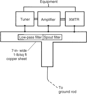
FIGURE 30.4 Ground system inside shack.
These connections are an important part of all the other grounding systems discussed, and they must therefore be low impedance all the way from dc to many megahertz. Further, the ground plane or ground buss so formed must be connected to the outdoor ground system(s) with as short a run as possible, so that the least possible amounts of both resistance and inductance are introduced into the total ground path. In one installation, the author was able to drop the copper sheet down from the table to connect directly to the ground system outside the building. The run was less than 40 in.
Unfortunately, some amateur radio operators and CBers use the building electrical ground wiring for the RF antenna ground of their station. Neglecting to install an outdoor ground that will properly do the job, they opt instead for a single connection to the grounded “third wire” in a nearby electrical outlet. In addition to being potentially dangerous, this is a very poor RF ground. It is too long for even the lower HF bands, it reradiates RF around the house in large quantity, and there’s just not enough of it to serve its intended purpose. Transmitters that depend on the household electrical wiring as the radio ground tend to cause radio and TV broadcast interference, as well as interference to other consumer electronics devices in their own home and in nearby buildings.
Tuned Ground Wire
If you use a power tool or a household appliance on the second or third floor of your home, or at the far end of a long three-conductor extension cord, you still have an effective power safety ground at the point of use, despite the relatively long run from your circuit breaker box in the basement. That’s because the wavelength of 60-Hz energy is measured in miles, and the extension cord represents a tiny fraction of a wavelength. However, from a lightning or radio standpoint, second- and third-story grounds are not grounds at all! The reason is because at radio frequencies your equipment chassis ground may be a substantial fraction of a wavelength distant from true earth ground. (Remember that typical lightning strikes include large amounts of energy at 1 to 3 MHz and above. At those frequencies, anything longer than a few feet is likely to see a significant induced voltage across its length.)
If you have ever been “bitten” or burned by RF energy when you happened to touch the chassis or a metal knob on your radio equipment while transmitting, you have felt firsthand the effect of having an inadequate RF ground in your radio room. Often the user thinks he or she has a ground simply because a wire has been run from the equipment chassis to a ground rod two floors below. That “ground” wire may be 25 or 30 ft in length—long enough to be a quarter-wave vertical on 20 m!
An alternative that some operators use is the ground wire tuner. (MFJ Electronics makes such a unit.) These accessories insert an inductor or capacitor (or even a full LC network) in series with the ground line. The user adjusts (or “tunes”) the device for maximum ground current while transmitting on the desired operating frequency. Although these tuners can bring your radio equipment common chassis connections to a virtual RF ground for purposes of providing proper antenna tuning, a low-impedance RF path to a single-point ground located outside the building, at earth level, is still necessary for lightning grounding.
Grounds for Antenna Efficiency
The success or failure of a radio antenna system often hangs on whether it has a good RF ground. Poor grounds cause many antennas to operate at less than best efficiency. In fact, it is possible to waste as much as 50 to 90 percent of your RF power heating the lossy ground under the antenna, instead of sending that RF into the air. This is especially true in the case of ground-mounted monopoles, such as a typical quarter-wave vertical, because the “missing” half of the antenna is the circle of ground lying within roughly λ/2 of the base of the vertical; RF energy delivered to the feedpoint of the vertical monopole and radiated into space must be balanced by return currents delivered to the transmission line via this ground path. Total effective ground resistance of typical soils in the circle beneath a vertical monopole can vary from a low value of, say, 5 Ω, up to more than 100 Ω, and RF power is dissipated in the ground resistance according to a simple resistive divider equation. The total resistance, RLOAD seen by the transmission line is
![]()
![]()
The total power, POUT, delivered by the transmission line is
![]()
The power radiated by the antenna is PRAD = I2LOADRRAD; expressed in terms of the total power delivered by the transmission line, it is
![]()
![]()
If, for instance, the effective ground resistance is 30 Ω, and the antenna is a full λ/4 vertical monopole having a radiation resistance of 30 Ω, also, then half the applied power, or 3 dB, is wasted in ground losses. Any increase in ground losses (usually as a result of an insufficient radial field) or decrease in radiation resistance (a shorter vertical) can conspire to drop the power radiated even further—perhaps to as low as 5 or 10 percent of the power available from the transmission line!
Soil Conductivity
Factors that affect ground resistance include the conductivity of the ground, its composition, and its water content. The effective RF ground depth is rarely right on the surface and—depending on local water table level—might be a few meters or so below the surface.
The conductivity of soil determines how well or how poorly the earth conducts electrical current (Table 30.1). Moist soil over a brackish water dome conducts best (coastal southern swamps make better AM broadcast radio station locations), and the sands of the western deserts make the poorest conductors.
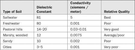
TABLE 30.1 Sample Soil Conductivity Values
Previous editions of this book described techniques for reducing the electrical resistance of soil through treatment with chemicals. Currently, the author does not recommend the approach. In addition to any possible environmental concerns, any benefit from salting will only be temporary and the cost and time required to repetitively salt a useful area surrounding the base of the antenna prohibitive. Salting only the area near ground rods is futile for improving antenna efficiency because the ground currents relevant to antenna efficiency travel laterally, near the surface of the ground—from roughly as far away from the base of the vertical as the vertical is tall—back to the antenna feedpoint. In contrast, focusing on deep ground rod conductivity is arguably of interest when attempting to maximize the dissipation of a lightning surge into the ground.
As discussed in Chap. 5, the soil directly underneath a horizontally polarized antenna is important primarily for establishing the effective height of the antenna (and, hence, its feedpoint impedance at its erected height above the ground surface). The soil within, say, a radius of λ/4 to λ/2 is important primarily for carrying radial return currents back to vertical monopoles. But with the possible exception of saltwater, any surface normally found under a vertical monopole is not a good enough conductor to seriously consider it as a substitute for copper radials.
Table 30.1 lists the electrical characteristics for a range of commonly encountered soils, along with those of saltwater and freshwater. Note that the highest-conductivity soil (“pastoral hills”) in the list is still approximately 200 times lossier than saltwater—and saltwater is nowhere near as good as copper! Bottom line: For superior vertical monopole efficiency, lay at least two dozen radials out under your verticals and quit worrying about your specific soil type!
Much farther from the base of your antenna, soil conductivity is important because it affects the first ground reflection of your transmitted signal and the last ground reflection of received signals. But for long-distance (DX) communication, optimum takeoff and arrival angles are usually in the 1- to 5- degree range, so we’re talking about bouncing the RF off soil at distances up to a mile away! Odds are high you don’t even own the land, much less have the fat wallet needed to salt acres and acres of ground. And for very long DX paths, there are additional ground reflections to consider. Ultimately, it’s probably cheaper and a lot less backbreaking labor over a lifetime to buy oceanfront property.
Grounding with Radials
The effectiveness of an RF ground system is enhanced substantially by the use of radials either above ground or buried just below the surface. In Chap. 10 we saw that a vertical monopole antenna is relatively ineffective unless provided with a good RF ground system, and for most installations that requirement is best met through a system of ground radials.
An effective system of radials requires a large number of radials. But how many is enough? Experimental results obtained in 1928 subsequently resulted in new regulations in the United States requiring broadcast stations employing vertical monopoles in the AM band (540 to 1600 kHz at the time) to use a minimum of 120 half-wavelength radials, but 120 was deliberately chosen to be at least twice the number at which the experimenters had found that practical improvement ceased to be meaningful. Recent modeling work has confirmed that nowhere near that number is necessary for non-broadcast services. Installing more than 30 or 40 λ/4 radials is not only expensive and time-consuming, but totally unnecessary, as well. The author has had a superior signal on 160 m for years using anywhere from 12 to 25 radials of various lengths.
Unlike elevated radials, which should be as long as the electrical height of the vertical, radials on the ground can be just about any length that is convenient, up to perhaps a half-wavelength. A radial in close proximity to earth has lost any pretense of being resonant at a specific length; better to think of it instead as one terminal of a long, skinny capacitor. From modeling and experiments a rough rule of thumb has evolved: Aim for the tips of adjacent radials on the surface of the ground to be about 0.05λ apart. At smaller spacings, no significant reduction in ground losses is noted, and when spacings start to exceed that figure, losses start to grow as an increasing percentage of the vertical’s return currents find their way into the earth instead of the copper wires.
A little thought will lead you to the conclusion that for fixed tip- to- tip spacing specified as a fraction of the wavelength in question, the shorter your radials are, the fewer you need!* This seems paradoxical at first, but what’s missing is the fact that your antenna’s ground return efficiency is not constant during this comparison; truly, shorter radials are not as good as longer ones, no matter how many of them you install. Stated another way, it is a waste of time and good copper to install “additional” short radials in an attempt to compensate for their shortness.
The ideal layout for a system of radials in a vertical antenna system is depicted in a view from above in Fig. 30.5. Here, the radials are laid out in a uniform pattern around the antenna element. This coverage provides both the lowest resistance and the best radiation pattern for the antenna. Tie all radials together at a common point at the base of the vertical, and connect that junction of wires to one side of the feedline—usually the shield braid when coaxial cable is used—and to the ground terminal on any remote matching network you may be using at the base of the vertical. If your radials are going to be part of your lightning surge grounding, use mechanical compression or brazed joints, rather than solder, for the connections.
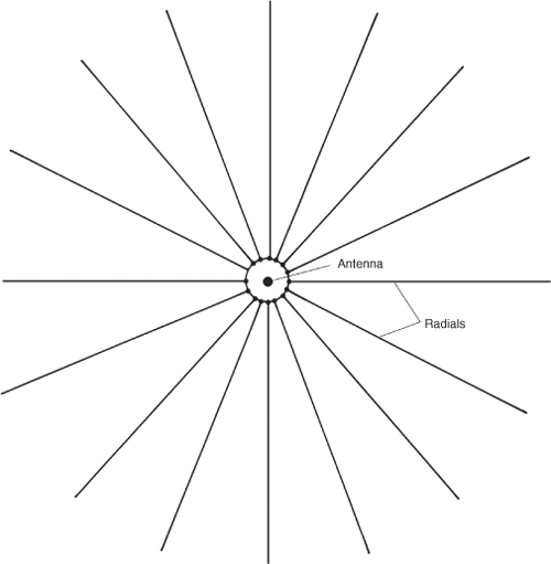
FIGURE 30.5 Radial pattern beneath a grounded monopole (vertical).
Here’s a Top 10 list (plus one bonus item) of other quick hints about radials:
• For verticals near a property line or a building, make the radials fit the circumstances; if they’re short on one side of the antenna and long on the other, no harm done.
• If you need to run a radial slightly “off course” for part of its run to get past a building or other obstruction, do it.
• Don’t bother connecting radial tips with circumferential wires; all the return currents from the antenna’s fields are radial in orientation. Similarly, adding chicken wire mesh under the tower is problematic; in return for lots of added conductor that may or may not be augmenting your original radials, you could be plagued after a couple of winters by rectification from a zillion corroded junctions where the wires of the mesh cross each other.
• Use just about any kind of copper wire you have on hand for your radials. Strip multiconductor cables into their individual wires, if you wish. The primary determinants of what wire to use are cost (if it’s free, use it!) and longevity on/in the ground.
• If you have to purchase any radial wire, get ordinary insulated THHN #14 house wire from a building supply store. The insulation will prolong the life of your radials.
• Even at kilowatt power levels, wire gauge is not critical. The primary reason for specifying #14 wire is so that it will stand up to stresses on it, such as when it is buried or when someone or something trips over it. Many radial fields consist of #18 or finer wire.
• Avoid stranded wire in outdoor applications.
• Ideally, your radials should lie on top of the ground for maximum antenna efficiency, but you can bury them an inch or two below, if necessary, to keep people and animals from tripping on them. Many amateurs have reported that sod staples, available at home and garden supply stores, are excellent for holding radials down and out of the reach of lawn mower blades until they sink into the grass and become part of the thatch.
• At least two suppliers of accessories to the amateur market (Array Solutions and DX Engineering) sell radial attachment plates intended to simplify the connection of large numbers of radials to the base of the antenna. Others, including the author, have formed a grounding ring from soft copper tubing purchased from the local hardware store and attached the radials to it with solder joints or noncorroding fasteners.
• If you have multiple verticals (a four-square, for instance), do not connect the radials of one vertical to those of another.
• Never directly connect copper to galvanized steel. Use a transition metal in between the two.
Elevated Grounds
Most users of VHF equipment are familiar with the ground-plane antenna—a vertical with either three or four radials, mounted atop a mast. The same technique can be used at MF and HF, but the mechanical challenges are not trivial. At VHF, the idea behind the ground-plane antenna is simple: a vertical monopole (whether λ/4 or 5λ/8 or any length in between) requires a return path for the “missing” half of the charged dipole structure that is necessary for electromagnetic radiation. Starting with a vertical dipole (Fig. 30.6), if we split the wire that is the lower half of the radiating element into four thinner strips, angle them upward by 45 degrees, and space them equally around the azimuth circle, we end up with a ground-plane vertical. Thus we have created an artificial ground plane high in the air, right where the vertical monopole needs it. A little knowledge of trigonometry will convince the user that three radials, spread 120 degrees apart, are sufficient to provide a return current path for all compass directions.

FIGURE 30.6 Transforming a vertical dipole to a λ/4 ground-plane vertical.
The ground-plane antenna is fairly easy to implement at frequencies as low as 7 MHz. In the 1960s and 1970s a very popular antenna was the Hy-Gain 14-AVQ (now the AV-14AVQ), a trapped vertical for 40, 20, 15, and 10 m. Propped atop a 20- to 30-ft mast, with a handful of radials sloping down from the base of the antenna, the antenna acquitted itself very nicely as a low-angle radiator on 40 m. In some installations the radials did double duty as guy wires for the mast. In such an installation, each combination radial/guy wire must have an insulator in it at a distance of λ/4 along the radial from the base feedpoint of the radiating element.
In recent years increasing numbers of hams have installed elevated radials under 80- and 160- m verticals. Unlike VHF ground-plane antennas or even the 14-AVQ, running controlled comparative experiments on 80 m and 160 m is a major undertaking. What has gradually come out of the anecdotes, experiments, and modeling, however, is that a handful of elevated radials (between four and eight) can be as effective as 30 or more radials on the ground—but only if the vertical and the elevated radials are well above the earth. Ideally, elevated radials should be at least λ/8 above earth ground, but good results have been reported with lower installed heights. Few amateurs have the resources to put up 160- m verticals whose base is 30 to 70 ft above the earth, so elevated radials are frequently installed as shown in Fig. 30.7.

FIGURE 30.7 Elevated radials for a ground-mounted vertical.
Compared to earth ground, which is lossy (dissipative), copper radials are essentially lossless. When elevated radials are too close to earth, radial return currents for the vertical are shared between the radials and earth, thus allowing some substantial fraction of the vertical’s return currents to be dissipated in the lossy earth. When the vertical and the elevated radials are far enough away from the earth’s surface, virtually all the return currents are collected by the elevated radials, even though there may be only a handful. “Far enough away” turns out to be λ/8 or more.
Unlike radials on the ground, elevated radials exhibit resonance in the same way that an antenna does. Thus, all radials for a given band should be cut to the same length and should all make approximately the same angle with the ground, insofar as possible. If the vertical (such as the 14- AVQ) is capable of multiband operation, a set of λ/4 radials should be added for each band to be used. The objective is to make the impedance at the feedpoint end of each active radial as low as possible in order to maximize the return currents it supplies the vertical monopole. One possible simplification might be to add traps so that a single set of four or eight radials serves multiple bands.