CHAPTER 28
Supports for Wires and Verticals
Antenna installation methods vary in complexity from those that can be performed by one person of moderate strength and agility all the way up to large-scale projects that are best left to professional antenna riggers. In this chapter we suggest techniques for erecting wire antennas and lightweight rigid verticals. In Chap. 29 we do the same for full-fledged towers. Keep in mind, however, that the information given herein is merely informal guidance and what you ultimately do should never be in violation of local mechanical, electrical, and other building codes or any zoning ordinances or restrictive covenants pertaining to your property.
Antenna Safety
Before dealing with the radio and performance issues, let’s deal first with a few antenna safety matters. You do not want to be hurt either during installation or during the next windstorm. Two areas of potential concern immediately present themselves: reliable mechanical installation and electrical safety.
CAUTION No antenna should ever be erected so the antenna, its feedline, its supports, or any part thereof crosses over or under a power line, transformer, or other utility company equipment—never, ever! Each year we read or hear about colleagues and innocent bystanders being electrocuted while installing or working on an antenna. In virtually all these tragic cases, the antenna came into contact with a power line. Keep in mind one dictum and make it an absolute: There is never a time or situation when any part of an antenna system should be placed near enough to electrical power lines that it can come in contact with them if the antenna, its feedline, or its supports fail or if the power poles or power lines themselves come down! And never, never use a utility pole or guy wire as an attachment point for any rope, halyard, tug line, or guy wire—not even temporarily.
Never rely on the insulation covering antenna wire or the power lines to protect you from high voltages on the utility company wires. Never assume that the power lines are insulated. Old insulation crumbles on contact with even a thin wire antenna, and even new power lines may have small breaks or weakened spots in the insulation, which may, after all, have been lying in an outdoor storage yard for a long time.
Even a simple wire antenna can be dangerous to erect if certain precautions are not followed. It is not possible to foresee all the situations you might face in erecting an antenna. The authors would love to give you a comprehensive list of all possible warnings, but this is just not feasible. You are on your own and must take responsibility for installing your own antenna. We can, however, give you some general safety guidelines and a few tips:
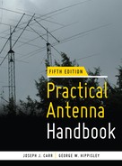
• Prior to starting the project, sketch the installation area to scale, as shown in Fig. 28.1, and draw boundaries of “safe working areas” based on the longest and tallest masts, towers, ladders, cranes, etc., that could fall, break, or tip over. Be sure to include the area around any electric utility drop wire from the power pole to the building as part of the “forbidden” zone. Then use stakes and colored ribbons or string to separate the “forbidden” areas from the work area. “Safe” doesn’t have to refer only to avoiding power lines. Ravines, structures, and electrified fences are some other common hazards you’d probably prefer not to drop your ladder on or into.
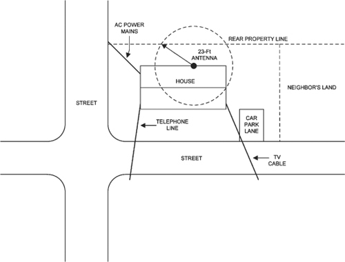
FIGURE 28.1 Antenna installation on suburban lot.
• Make a list of all tools and machinery you expect to need for the project, and make sure you either own them, can rent them, or have friends who will bring or loan them. One of the leading sources of personal injury and property damage during antenna projects is failure to use the right tool for the job at hand.
• If electricity is required in the work area(s) during the project, make sure that adequate three-wire 115 VAC power with functioning ground fault interruption (GFI) circuitry is available at the site. Most municipalities allow GFI protection to be inserted in one of two places: as part of the circuit breaker for the circuit in question or as part of the first outlet on that run from the breaker. If needed, GFI installation should be handled only by an electrician licensed to work in your community.
• Make sure the planned tasks don’t require Superman for their successful performance. If climbing is involved, make sure experienced climbers with all the appropriate climbing gear are involved. Any climbing at all, even on ladders, can be taxing. Many common antennas, including small Yagis or quads, are deceptively lightweight on the ground, but when you get up in the air even a short distance they become remarkably difficult to handle, especially in the presence of even light breezes.
• Be aware that wind speeds (and, hence, the effective wind load a given antenna represents) increase with height above ground, especially if there are buildings, trees, and other obstructions to slow the wind below their tops. The wind also has a bad habit of coming up at the worst possible time—usually when you’re about to attach the antenna to its support mast. A friend of one of the authors fell from the roof of his two-story beach house, fracturing his pelvis and a leg when an offshore gust of wind came up suddenly and caught a TV antenna. It acted like a hang glider and pulled this very strong man off the roof. Two months of orthopedic casts and a year of physical therapy followed—not to mention lost wages. Be careful!
• Never tackle an antenna project with no one else around. Even if it is a project that can easily be handled by one person (stringing a dipole, for instance), make sure a family member, friend, or coworker is on the premises, within earshot, even if he/she is doing other things.
Probably the single best piece of advice we can impart is the time-tested Boy Scout motto: “Be prepared!” There is no substitute for planning ahead. Taking time before the day of the project to define and think through the many individual tasks that together result in a successful antenna installation is the single most important thing you can do before you tackle the job or your crew of helpers arrives on the scene. Knowledge of what you face, coupled with hard-nosed, sound judgment and some common sense, are the best tools for any antenna job.
One good rule is to always work under the “buddy system”. Invite as many friends as are needed to do the job safely, and always have at least one assistant, even when you think you can do it alone.
Install only antennas of the best materials and workmanship in order to minimize the need to repair or replace them. It is not just the electrical or radio reception workings that are important—but also the ability to stay up in the air in an often unfriendly environment.
When planning an antenna job, keep in mind that pedestrian traffic in your yard possibly could affect the antenna system. Wires are difficult to see; if an antenna wire is low enough for vehicles, people, or animals to come in contact with it, injury and damage can result. In the United States, even when the person is a trespasser (or even a burglar!), the courts may hold a homeowner liable for injuries caused to the intruder by an inappropriately designed and installed antenna. Take care for not only your own safety but also that of others.
Consider a typical scenario involving a four- or five-band trap vertical antenna (Fig. 28.2). It will be 18 to 26 ft tall, judging from the advertisements in magazines, and will be mounted on a roof or mast 12 to 30 ft off the ground. The total height above ground will be the sum of the two lengths—perhaps 30 to 60 ft overall. You must select a location at which a 30- to 60-ft metal pole can be erected—and can fall—safely. This requirement limits the selection of locations for the antenna. In particular, if the drop wire from the power pole to your house attaches to the house high on an end wall rather than coming in underground, you probably will not be able to find a proper location for a house-bracketed or roof-mounted antenna of that overall height.

FIGURE 28.2 Mast-mounted vertical antenna.
When installing a vertical antenna, especially one that is not ground-mounted, make sure that you have help. It takes at least two people to safely install a standard HF vertical antenna, and more may be needed for especially tall or heavy designs. Wrenched backs, smashed antennas, crunched house parts, dented vehicles, and other calamities are rare with a well-organized work party that has sufficient hands to do the job safely.
Wire Antenna Construction
Volumes have been written on the electromagnetic design and analysis of wire antennas, which are primarily employed in the MF and HF regions of the radio spectrum. What often seems to be missing, however, are practical details of the mechanical aspects of wire antenna construction and installation, so let’s take a look at some of the basics.
Wire antennas come in many forms, but good techniques for construction and support are pretty much the same regardless of the wire configuration, so we shall use our old friend the half-wavelength horizontal dipole for our examples. In its most common configuration (Fig. 28.3), the HF λ/2 dipole is insulated from other conducting materials at each end and supported by ropes, cables, or other wires attached to trees, buildings, masts, or any other structures of suitable strength and height in fixed positions.

FIGURE 28.3 Typical center-fed wire dipole.
Center Insulators and Feedline Connection
The λ/2 dipole’s nominal feedpoint impedance at resonance is 73 Ω in free space and at multiples of a quarter-wavelength (λ/4) above ground, so it is a reasonably good match to standard 50- or 75-Ω coaxial cable. When fed with coax, a 1:1 balun transformer or common-mode RF choke is often inserted at the feedpoint.
Far more important to the long-term success of a horizontal wire than a balun are the quality, strength, and weather resistance of the electromechanical connection between the antenna and the feedline in the face of prolonged exposure to the environment. In virtually all installations (except perhaps for the attic dipole), this junction is subject to temperature and humidity changes, precipitation of all kinds (including ice and snow in many climates), ultraviolet rays from direct sunshine, continual vibration, and abrupt changes in tension resulting from gross motion in the wind.
A common (but poor) practice is to strip the insulation back a few inches at one end of a coaxial cable, part the braid and center conductor, and connect them with ordinary electrical solder to each side of the dipole. We then wonder why the darn thing breaks apart in the next windstorm or why our VSWR measured back at the radio room seems to change over time. Unprotected solder joints exposed to the elements eventually turn gray, brittle, and powdery, and eventually crack under environmental stresses that conventional solder was never designed to resist. Solder for electrical and electronic circuits is not intended to provide a mechanical connection—it has little strength—nor is it meant to be exposed to the elements. Equally disastrous, coaxial cable that is open at one end is very hard to protect from moisture ingress; over time, it can become saturated with water. Over the years, there have been many reported cases of water dripping from the indoor end of cables onto the radio desk!
Even if you elect not to use a balun transformer, a ready-made center insulator that accepts a PL-259 or similar connector helps minimize or eliminate many of these problems. Figure 28.4A shows a common form of center insulator for use with dipoles and other wire antennas. At the bottom is an SO- 239 coaxial cable receptable, shielded from direct rainfall by the assembly above it. Two eyebolts on the sidewalls provide mechanical strain relief for attaching the two halves of the dipole to the insulator. Although this particular style of center insulator is a compromise because it includes solder connections, if enough slack is provided in the pigtails that attach to the solder lugs the actual solder joint is under little or no mechanical strain and is far less likely to fail from stress-related mechanisms than the old-fashioned junction described above. Figure 28.4B shows a similar center insulator with a self-contained 1:1 balun.
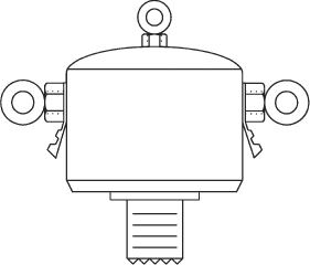
FIGURE 28.4A Center insulator.
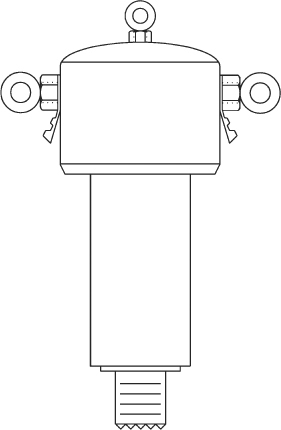
FIGURE 28.4B Center insulator with built-in balun.
A recommended way to connect a wire dipole to the device is shown in Fig. 28.5. For simplicity, only one side is shown, but the other side is identical. The λ/4 antenna segments (length B in Fig. 28.3) typically are made of #12 or #14 antenna wire, but the authors have used wire as large as #10 and as small as #18 for transmitting applications; the exact gauge is not important except that larger-diameter wire is heavier and sags more, and very thin wire ultimately is not strong enough to support the weight of the center insulator and feedline. In years past, stranded wire was often used, but oxidation of the strands inevitably occurs and may result in some additional loss of transmit signal and the application of large RF voltages to oxidized junctions, so it is no longer favored. Conventional house wiring (THHN) found at electrical supply stores and discount home suppliers can be used (with or without its insulation), but be aware that it is soft-drawn copper and can stretch in response to excessive tension such as that encountered during windstorms by dipoles strung from trees without provision for the movement of branches. (Most antenna tuners can compensate for the changing impedance caused by long-term stretching; occasional retensioning of the end support lines may also be required.) To avoid stretch, some recommend copper-clad steel core wire (Copperweld is one well-known trade name), but others have encountered problems with voids in the copper, pitting and rusting, and ultimately failure of the wire from poorer quality “off brands”. Copper-clad steel is also quite “springy” and very difficult to work with unless it is always kept under tension once unreeled. Given a choice, the author would rather have a stretched dipole than a snapped dipole!
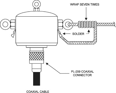
FIGURE 28.5 Center insulator connections.
Pass one end of one side of the dipole through an eyebolt and then double it back and twist it onto itself four to six times to ensure that no slippage of the wire through the eyebolt will occur when the antenna is erected and put under tension. Bare an inch or so of the wire at the end of the pigtail with steel wool, sandpaper, or a utility knife until the copper is clean and shiny all around the bared section. Form the short section of wire between the eyelet and the solder lug into a drip loop and insert the end of the wire into the shank of the solder lug. Be sure to crimp the wings of the solder lug around the wire end with a pair of pliers. Then, while keeping the assembly perfectly still, solder the terminal shank and wire with solder having a resin core, not plumber’s solder. Some people prefer to use a completely separate wire as the “pigtail”, but that doubles the number of solder joints. Whichever approach is used, the intent is that there be no tension at all on the pigtail when the antenna is up in the air. These steps are best performed with the dipole antenna laid out on the ground in a straight line, preferably (weather and tools permitting) in or near the area where it will be hoisted.
NOTE Use only resin-core solder for antennas! Typical solder is 50/50 or 60/40 lead/tin ratio and may be labeled “radio-TV” or “electronic” or something similar. Newer solder alloys, without any lead, are also available. Most plumber’s solder is acid-core and will destroy your connection within a short time.
The life of the solder joint can be extended by painting it with nail polish or spraying it with an acrylic lacquer such as Krylon, after the joint has cooled. As with the soldering process itself, the entire assembly should be not be moved or jostled until the coating has dried.
Keep in mind that even “new” copper wire needs to be sanded or scraped. Bare copper wire may, in fact, have a clear enamel insulation on it that isn’t obvious to the eye. But all bare copper oxidizes, forming an insulating layer over the conductor; the early stages of that process result in only a slight dulling of the surface, so cleaning off the wire immediately prior to soldering it is an excellent habit to form. Similarly, when preparing the center connector, it is also good practice to use steel wool or sandpaper on the solder lugs to remove any oxidation that may have formed over time. Oxidized metal simply cannot be soldered!
An SO- 239 UHF coaxial receptacle (socket) on the bottom of the center support device shown in Fig. 28.5 accepts any feedline terminated in a standard PL-259 plug. Once that connection is made, wrap high-quality black vinyl electrical tape around the joint, starting on the vinyl cable jacket below the plug and continuing completely over and past the PL- 259 until reaching the molded case that supports the SO-239 receptacle. Half-lapping the tape like siding or roof shingles should ensure minimal water ingress at the end of the coaxial cable. To minimize water vapor ingress caused by changes in humidity, the vinyl tape should also be sprayed with acrylic lacquer or painted with nail polish. Alternatively, use heat-shrink tubing and a heat gun to totally encase the connection from the threads of the SO- 239 above the PL- 259 to the outer jacket of the cable a half-inch or so below the bottom edge of the PL-259.
In most installations, the weight of the feedline will keep the entire center assembly oriented as shown in Fig. 28.5, thus eliminating the need for a drip loop on the coaxial cable. If, however, a specific installation results in the SO- 239 connector being anywhere other than beneath the body of the device, the coaxial line near the connector should be routed with a half-loop that is arranged so as to send any precipitation running along the cable away from the connector.
At the top of the center insulator a small eyebolt is provided for strain-relief of the system or for suspension from a center support (such as when the antenna is an inverted-vee). One disadvantage of coaxial cable and commercial center insulator assemblies (as compared to open-wire line directly connected to the two sides of the dipole) is that both add quite a bit of deadweight to the center of the antenna. Unless some kind of auxiliary support (nylon twine, polypropylene rope, or small-diameter aircraft cable pulling up to a high point on a tower, mast, or tree) is available, the sag in a dipole for 80 or 40 m fed with RG- 8 or RG- 213 cable may be unacceptable to the user. If the VSWR on the line is kept close to 1.0:1 or power to the line is kept substantially below 1000 W, some weight can be removed by using the smaller-diameter RG- 58 or RG- 59 cables instead of RG- 8—especially at 10 MHz and below, where line loss is lowest.
The longer, lower barrel of the center insulator shown in Fig. 28.4B indicates the presence of either a 4:1 or 1:1 impedance ratio balun transformer. The 1:1 size is recommended for ordinary dipoles, whereas a 4:1 unit is a good match for folded dipoles and certain other wire antennas with feedpoint impedances substantially larger than the Z0 of the feedline.
Some users form the coaxial cable into a 6- to 12- in multiturn loop just below the coaxial connector, as shown in Fig. 28.6. This forms a common-mode RF choke intended to keep currents from flowing on the outside of the cable shield, thus helping to keep the feedline from becoming an unintended part of the radiating antenna. The number of turns is inversely proportional to the lowest operating frequency. For an 80- m dipole, 16 turns of 8- to 12- in diameter is probably not too few . . . but will be very heavy! Bind the turns together with black electrician’s tape or some similar adhesive medium and then fasten the entire loop to the top eyelet with stout string or fishing line for strain relief.
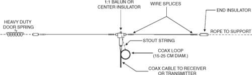
FIGURE 28.6 Dipole and wire antenna installation.
End Insulators
Over the years, end insulators have been made from wood, glass, ceramics, plastics, and composites. In fact, at low power levels (say, 100 W or less), garden-variety polypropylene rope often used for stringing the dipole up is perfectly adequate as its own insulator! Nonetheless, since the wire ends of a dipole are usually high-voltage points, take care to keep the conductors away from flammable surfaces. More than one licensed amateur has set a tree on fire by transmitting into a wire draped across tree limbs!
End insulators come in a large variety of shapes and sizes. Examples of two basic shapes are found in Fig. 28.7. Figure 28.7A depicts the standard strain insulator, and Fig. 28.7B is representative of an egg insulator. The egg insulator has two sets of wire grooves and through-holes that are orthogonal to each other (only one set is shown). Wire passes through one hole and its grooves, while the supporting rope passes through the other hole/groove set. The purpose of the orthogonal holes is to prevent the antenna from totally separating from the support line if the insulator should fracture.

For higher power levels, the standard strain insulator of Fig. 28.7A is preferable. This style often has a number of grooves or ridges along the body that serve to lengthen the effective electrical path between the two ends of the insulator, thus reducing losses in the insulator while increasing the breakdown voltage between its two ends. This is particularly important in locations where airborne contaminants gradually collect on the surface of the insulator.
End insulators can be purchased new from many of the radio stores listed at the back of this book; preowned components can be found at hamfests and radio conventions or on Internet sites such as eBay. For the experimenter interested in “rolling his or her own”, typical materials for fabricating strain insulators include ceramic, glass, nylon, plastics, and (treated) hardwoods. (Short lengths of hardwood stock can be drilled at each end for wire or rope, then treated with an exterior urethane or other protectant.)
Strictly speaking, the egg insulator of Fig. 28.7B is not designed to be an end insulator for transmitting antennas. The distances between the antenna wire and the support line are not very large and, hence, are subject to breakdown at high power, since at least one end of a wire antenna is a high-voltage point. Egg insulators are okay to use at low power levels or for “receive only” and temporary installations, but so is polypropylene rope! On the other hand, the egg insulator is potentially much stronger than a comparable strain insulator because the interweaving of the wire and/or rope through their respective holes puts the egg in compression rather than tension. For that reason, the egg insulator and its rectangular sibling seen on power pole guy wires are the only types to use when it is necessary to electrically break up long guy wires into multiple shorter sections.
Figure 28.8 shows how to make connections through an end insulator. The electrical connections to the antenna wire are the same as for the center insulator. The only proviso here is that for transmitting antennas it is wise not to leave any sharp points sticking up. The ends of a λ/2 dipole experience high RF voltages, and sharp points tend to cause corona sparking. Cut off any extraneous leads that form sharp points, and then smooth the whole affair down with tinning (i.e., solder).
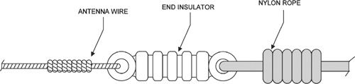
FIGURE 28.8 Connections to end insulators.
The rope is dressed in a manner similar to the wire, but it must be knotted with a self-tightening knot—i.e., one that tends to clamp down on itself as the support line is tensioned. Some people use the hangman’s knot, but this seems a bit excessive. The bowline is particularly useful, especially if the line is always in tension, and the knot can easily be “broken” and untied later.
Folded Dipole Construction
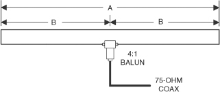
As discussed in Chap. 6, the folded dipole (Fig. 28.9) consists of two close-spaced conductors shorted together at both ends, but only one of the conductors is split in the center for the feedpoint. The free-space feedpoint impedance at resonance is around 290 Ω, so it makes a good match to 300- Ω, television antenna twin-lead. (Often the antenna itself is cut from the same roll of twin-lead!) Alternatively (as shown in Fig. 28.9), a 4:1 balun transformer at the feedpoint provides a match to 75-Ω, coaxial cable. Despite the fact that 300-Ω, TV twin-lead is disappearing from the market, the folded dipole maintains a following among SWLs and hams. A preassembled folded dipole and feedline rolls up into a small storage space, weighs very little, and can be rapidly deployed in an emergency or portable scenario.
Neither the conductors nor the dielectric of ordinary TV twin-lead are particularly strong, so some ingenuity is required to keep the terribly weak 300- Ω, twin-lead from breaking at the slightest provocation. Figure 28.10 shows a solution developed by one fellow (admittedly a fine worker in plastics and other materials); he fashioned a center insulator and two end insulators from a piece of strong Lucite material.
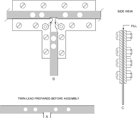
FIGURE 28.10 Center insulator for ribbon cable folded dipole. (A) Cable preparation. (B) front/back view. (C) Edge view.
The 300- Ω TV twin-lead is prepared as shown in Fig. 28.10A. One conductor of the twin-lead is cut at the planned feedpoint, and the insulated wire freed from the center dielectric material a distance of about 0.5 to 0.75 cm in both directions, using a match and/or small diagonal (side) cutters. Use the same tools to strip the insulation from the two wire ends just created. A hand punch—either a large-size leather punch or a paper punch—places two or three holes in the center insulation on either side of the break.
The center insulator is shown in Fig. 28.10B. It is made from a piece of strong plastic, Lucite, or other insulating material. Two identical sections, front and back, are needed. A number of 5-mm holes are drilled into both pieces at the points shown to clamp the twin-lead. A pair of solder lugs provides a mechanical tie-point for connections between the antenna element and the transmission line. The nuts and small bolts that fasten the two halves of the insulator are nylon to eliminate any possibility of short-circuiting the two terminals or the two sides of the twin-lead that form the antenna.
A side view is shown in Fig. 28.10C. Note that the twin-lead causes a gap that can catch water and makes it possible to break one or both insulators by overtightening the nuts. To prevent these failures, a gasket of similar material is glued into the space as filler. The gasket material should be the same thickness as the twin-lead.
Rather than burden this antenna with the weight of coaxial cable, the twin-lead feedline should be run to an ATU for balanced lines.
An end insulator for twin-lead folded dipoles is shown in Fig. 28.11. It is constructed in a manner similar to the center insulator. The clamping fixture can be fabricated from metal such as 3- to 6- mm brass or copper stock. The ends of the antenna wires are shorted and soldered together, so use of a conducting material at the ends is not a problem.

FIGURE 28.11 Twin-lead folded dipole end insulator.
An end insulator is then used with a rope in the normal manner. A chain-link section or carabiner is used to connect the clamping fixture and the end insulator.
Alternatively, the clamping fixture can do double duty if it is the same material as the center insulator. In that case the other end insulator and chain link can be ignored. If you opt for this approach, it is a good idea to bevel and polish the rope hole on the clamping fixture to prevent chafing of the rope, or insert a guy wire thimble of an appropriate size through the hole in the fixture.
Supporting the Wire Antenna
Figure 28.6 shows the dipole installed. The ends of the two wire elements are connected to end insulators, which are in turn supported by rope to a vertical support (e.g., mast, tree, roofline of the house). Although shown perfectly horizontal here, the actual installation will droop in the center due to the weights of the center insulator or balun, the coaxial cable, and the wire itself.
If either end of the dipole is supported by a tree limb or anything else that can move in the wind, add a door spring—just beyond the end insulator—in one support line. The strength of the spring should be chosen such that the normal tension in the support lines on a calm day causes the spring to be less than halfway extended. For an 80- m dipole with substantial feedline weight, a residential garage door spring is most likely to be appropriate. Most local hardware stores carry an assortment of door springs having various tension ratings.
Trees, Masts, and Other Supports
The end supports of the antenna can be anything that supplies height and is strong enough: a mast, a tree, or the roofline of a building. Figure 28.12 shows the use of a mast, but other forms of support can be used as well. To facilitate easy raising and lowering of the antenna for maintenance and tuning, the support rope should not be tied off at the top, as is true in all too many installations; instead, it should be brought down to ground level, just like the halyard of a flagpole. Be sure to provide enough “dead slack” to make lowering the antenna feasible, although once a halyard is created, it can be lengthened temporarily, as needed, to allow the antenna to be pulled sideways (i.e., along its axis) during the raising or lowering process.

FIGURE 28.12 Mounting mast schemes.
The ideal support is arguably a climbable tower (or perhaps a very tall building with an elevator to the roof), but most dipoles and other wire antennas are strung from tall trees. How do we get the antenna up high in the trees? Here are some thoughts about a variety of approaches:
• For those with strong throwing arms whose trees aren’t very tall, a baseball with a ![]() -in hole drilled through its center may do the trick. Simply tie one end of some light nylon twine through the center and a half-circumference of the ball. Lay out the twine on clear ground in front of you. (Clearly, this doesn’t work very well in the middle of the woods!)
-in hole drilled through its center may do the trick. Simply tie one end of some light nylon twine through the center and a half-circumference of the ball. Lay out the twine on clear ground in front of you. (Clearly, this doesn’t work very well in the middle of the woods!)
• Many techniques start with a projectile trailing fish line behind it as it is launched, since fish line is lighter than commonly available twine. The fish line should be wound on a spinning or fixed spool fishing reel. Attach the reel (with duct tape) near one end of a 2- or 3-ft length of wooden dowel, and push the other end into the earth at about a 45- degree angle so it is aimed up high in the targeted tree. There is a tradeoff between the strength of the fish line and how much total weight the projectile can haul up in the air behind it; experiment with different line weights in conjunction with your chosen reel and projectile. Once the fish line is up and over the target tree, attach nylon twine to the far end and reel the fish line back in. Then attach the halyard or an intermediate line to the end of the nylon twine that has been pulled through the tree top. (An assistant to spool out the twine is an extremely helpful addition to this part of the project!)
• One manufacturer sells a slingshot in the amateur radio market. The projectile is typically a metal ball with a tab for tying fish line to, or a large metal hex nut from the user’s parts bin after the metal ball has become lost. Many people have had success with a slingshot, but the author has found its aiming accuracy to be less than that of other approaches, and the elastic sling can deteriorate over time.
• For years the author favored a small bow and arrow given to him by a helpful neighbor. Three modifications must be made to conventional arrows:
![]() Remove the pointed tips (to avoid injury to bystanders, and to avoid having the target tree look like a porcupine).
Remove the pointed tips (to avoid injury to bystanders, and to avoid having the target tree look like a porcupine).
![]() Add mass (weight) to the nose of the arrow; a half-dozen framing nails (with large heads aimed forward) can be held in place around the circumference of the arrow at its head long enough to be taped with electrical or duct tape.
Add mass (weight) to the nose of the arrow; a half-dozen framing nails (with large heads aimed forward) can be held in place around the circumference of the arrow at its head long enough to be taped with electrical or duct tape.
![]() Drill a small hole, large enough to thread fish line through, about an inch or so back from the tail of the arrow.
Drill a small hole, large enough to thread fish line through, about an inch or so back from the tail of the arrow.
Used in conjunction with the spinning reel on a dowel stuck in the ground, this bow-and- arrow outfit allowed the author to put fish line in the tops of trees as tall as 60 ft.
• For greater heights and better accuracy, borrow or purchase a bowfishing rig. New sets are expensive, but archery shops often have trade-ins available at a very modest price. The most important element is the compound bow with a tapped hole and matching metal post for direct mounting of a spinning reel. Purchase five or six arrows with removeable points and prepare them as described here. With this setup, the author has sent appropriately sized fish line over the tops of 100-ft trees!
• To get the fish line to drop straight down the back side of the targeted tree (instead of continuing on beyond the tree some distance), halt the flight of the arrow just after it passes the top of the tree with a slight turn on the handle of the fishing reel. With practice, you can get the hang of this.
• Never try to retrieve the arrow by reeling it back in, up through the tree. Instead, always untie or cut the fish line at the arrow, rewind the empty fish line, and retie the arrow onto it back at your launch site.
• Wait for a calm day for all of these techniques.
• For the ne plus ultra, consider a potato launcher with tennis balls. Search the Internet for examples of how enterprising amateurs and others have modified these powerhouses to lay lines over the tops of the very tallest trees.
• If all else fails, pay a tree-climbing professional to place a “permanent” halyard mount near the top of your chosen trees.
CAUTION Always make sure the area around you and well beyond the targeted tree are clear of humans and animals before launching any projectiles. Even blunt-tipped arrows or hex nuts can cause serious injury!
Halyards and Other Support Lines
There are many choices for materials to use as a halyard or support line, but not all of them are good choices. Of paramount concern is long-term exposure to sun, wind, and moisture. In general, natural cordage (hemp, for instance) is a very poor choice except, perhaps, for a very short period (e.g., a few weeks). Nylon rope—despite having a much longer life—is far too stretchy. Instead, various “poly” compounds, including polyester and polypropylene, are worth considering, as is braided Dacron. Possible sources include large discount stores, building supply stores, boat dealers, outdoor (mountaineering) stores, your local hardware store, and a number of stores specializing in Internet sales, as listed in App. B. If total cost is an issue, careful shopping is a must; prices for comparable cordage may vary by as much as 4:1, depending on the market the seller is focused on.
Keep in mind that the safe working range for rope is typically less than 15 percent of its rated breaking strength. Thus, for an antenna that experiences up to 100 lb of tension during windy weather, a 750- lb rated rope should be on your shopping list.
Choosing the best diameter for your cordage is a tradeoff among required strength, size and cost of any pulleys (or blocks, in nautical terminology), and what is comfortable for pulling by hand (preferably with reinforced gloves). For supporting a typical dipole, somewhere around ![]() -in is a good starting point.
-in is a good starting point.
Virtually all cordage will eventually unravel at a cut end unless the end is treated. Laid or twisted three-strand rope can be eye-spliced or back-spliced, but braided ropes will need to have their ends fused (melted), taped, or whipped with twine. Fusing can be done with a soldering gun that has a special tip, a propane torch, or even (on a windless day) a simple match. Always fuse cordage outdoors; the fumes from heated synthetics should not be inhaled, and burning poly rope ends often melt and drip on the floor.
The antenna support line is connected to a spring on one end (see Fig. 28.6) and/or a counterweight on the other end. As mentioned earlier, the spring should be stout enough so that it is partly extended on a calm day with the antenna support lines normally tensioned. (Ideally, with no wind the spring should be extended less than 50 percent of its total possible expansion.) For an 80- m dipole and about 100 ft of open-wire line, both constructed from #10 enameled copper, a stiff garage door spring seems to work best. The author’s 80- m dipole has stayed up for nearly 20 years using this approach!
The counterweight should be just enough to balance the weight of the antenna for a reasonable amount of sag along the wire—probably between 15 and 40 lb for the 80- m dipole and OWL described in the previous paragraph. As wind causes the supporting tree limbs to move up and down or back and forth, the counterweight rises and falls, thereby reducing the chances of snapping a support line or the antenna wire itself. The choice of counterweight is limited only by your imagination: drapery cord weights, a small bucket of rocks, a gaggle of fishing weights, a cinder block, and (in one case) a burned- out automobile starter motor. (The mounting hole on the front boss of the motor was ideal for accepting the rope!) Just be sure to locate the counterweight where it cannot harm anyone or anything should the rope break. In that respect, it’s helpful to keep the counterweight in balance at a point no more than a few feet above the ground, if possible.
Don’t underestimate the value of making the dipole out of ordinary soft-drawn copper (house wiring, in other words). Although you may periodically have to retension the support lines, such wire is more able to withstand the shock of wind gusts snapping the tops of trees around than copper-clad steel is. (Of course, stretch in the antenna wire may change its resonant frequency a little bit, but dipoles that are longer than λ/2 exhibit a tiny bit more gain in their main lobe. If an ATU is used, the stretch is immaterial; if not, perhaps it will be necessary to lop a foot or so off each end of the dipole every five or six years.)
Figure 28.13A and B show two methods for making the connections at the top of a supporting mast. Although egg insulators are shown, any kind can be used. A pulley is mounted at the top of the mast with a link section and a stout eyebolt or screw-eye that passes through the mount. (A simple screw-eye will not harm a tree, but never wrap wire or rope around a tree trunk or branch; it’s a sure way to kill the tree.) Make the downhaul rope a closed loop so you can raise and lower the antenna just like a flag.
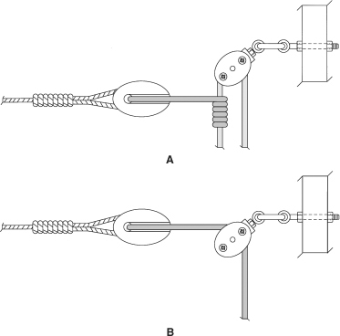
FIGURE 28.13 Two alternate pulley systems for wire antenna mounting.
In theory, a pulley is the best way to change the direction of a support line’s path, but few users are willing to pay for the right pulley for the task. The wrong device will tend to rust if made of ferrous metal, or crack if made of plastic. Equally important, the size of the pulley and the diameter of the cordage running through it must be correctly matched to avoid jams. The smaller the diameter of the pulley sheave, the shorter the life of the rope that lies in its groove. When selecting a pulley, make sure the groove is neither too wide nor too narrow for the size of line to be run through it. All in all, a pulley is not always the best solution if you have neither the time nor the inclination to select and pay for the right one.
Figure 28.14 shows a “poor man’s” pulley, suitable for temporary installations or lightweight (i.e., higher-frequency) dipoles. In this approach, a U-bolt is fastened to the top of the support mast. If the U-bolt is made of brass or galvanized steel, all the better, for it will not corrode. (In general, automobile muffler U-bolts and inexpensive plated U-bolts sold at the local hardware store will rust almost immediately; do not use them!) The rope can be passed through the U-bolt as in the pulley system but without fear of jamming. Be sure to install the U-bolt all the way up to the threads so that the rope has no chance to chafe against them.

FIGURE 28.14 U-bolt end mounting.
The method shown in Fig. 28.15 can only be loved by equestrians! A brass stirrup replaces the U-bolt. If you have switched to cars or trucks and no longer need your horse stirrups, then perhaps this is a viable means of attaching the support rope to the top of the mast.

FIGURE 28.15 Stirrup end mounting.
Strain Relief of the Antenna
For long dipoles with heavy center insulators and coaxial cable feedlines, the ideal installation includes a high center support capable of supplying strain relief and thus minimizing sag at the dipole center. Such a support also reduces longitudinal forces (tensions) on the dipole wires, end insulators, and halyards or hoist lines at both ends. Most commonly it is used with inverted-vee antennas, where the center of the antenna is pulled up high on the only available tall support.
Figure 28.16 shows an alternate method of strain relief for the center insulator or balun to reduce total sag from the height of the dipole ends to its center. A strong messenger cable is run between two end supports (which must themselves also be quite strong), and tensioned for minimal sag. By suspending the center of the dipole from the messenger, forces on the various electrical and mechanical components of dipole are substantially lessened. If the messenger cable is a conductor (stranded galvanized steel guy wire material is a favorite), it should be broken up with insulators to prevent detuning the wire antenna. However, there’s no reason the messenger cable can’t be run at right angles to the antenna wire (using an entirely different pair of end supports), in which case the need for insulators disappears.

FIGURE 28.16 Strain relieving the center insulator or balun.
Installing Vertical Antennas
At frequencies above 5 MHz, erecting and supporting HF verticals—both ground-mounted and elevated ground planes—is a relatively easy task for two people, provided the vertical is made of aluminum tubing strong enough to support itself during the brief period when it is being tilted from a horizontal to an upright position. At lower frequencies, verticals should be treated as towers (Chap. 29) or erected with the help of extensive rigging—often including some form of gin pole—and a larger crew.
For years the Hy-Gain 14- AVQ (now sold as the AV-14AVQ) has been a popular multiband vertical monopole. By using three parallel-resonant traps and a small capacitive top hat, the antenna provides a physically short vertical (18 ft overall) that is an electrical quarter-wavelength on 40, 20, 15, and 10 m. (The design is essentially unchanged from the original, pre-WARC band, model, so there is no guarantee of low SWR on the 17- and 12- m bands.) It can be ground-mounted or elevated atop a mast as in Figure 28.17. In either case, the antenna requires radials, but the number and length are different for the two cases. When ground-mounted, at least 16 (nonresonant) radials that are roughly as long as the vertical is tall (18 ft) should be laid out in a circle around the base of the antenna. When elevated, however, three (resonant λ/4) radials for each band, equally spaced around a 360- degree circle, are sufficient.

FIGURE 28.17 Mounting commercial trap vertical.
Ground-mount installation of the AV-14AVQ and similar verticals is simplicity in itself: Drive a 3-ft length of 1½- in OD steel post into the ground, stand the assembled vertical upright, and clamp its base to the post with the U- bolts supplied. To complete the installation, attach radials to the base or add a ring of copper wire or soft copper plumbing tubing around the base as an attachment point. Install a lightning ground (see Chap. 30) of multiple 8-ft ground rods in a circle with a radius of about 8 ft centered at the base of the vertical, and connect each ground rod directly and separately to the base with #6 or heavier gauge wire. Finally, connect 52-Ω coaxial cable at the bottom of the base as shown in Fig. 28.18A or 28.18B and weather-seal the connection with heat-shrink tubing or a half-lap winding of electrical tape (as described earlier in this chapter) and a spray coating of clear acrylic lacquer. Although Hy-Gain does not require or suggest the use of guy wires for the vertical itself, a single set of lightweight, nonconducting guys such as nylon twine or ¼- in poly rope tied just above or just below the middle trap is not a bad idea unless your installation location is such that the antenna is at greater risk from people tripping over the guy ropes than it is from high winds.

FIGURE 28.18A Feeding the mast-mounted vertical antenna.

FIGURE 28.18B Feeding the ground-mounted vertical antenna.
In years past the author preferred the performance of the 14- AVQ as an elevated ground plane, even though that installation is a little more involved. Telescoping TV antenna mast material, such as that long sold by RadioShack and others, is suitable for getting the base of the antenna 15 ft (corresponding to about λ/8 at the lowest operating frequency) or more up in the air. Because three λ/4 radials are required for each operating band, the radials for the lowest band (40 m) can double as guy wires for the top of the mast, if you so choose. The tradeoff is that adjusting the length of the radials for minimum SWR may be a little more difficult if the radials are doing double duty as guy wires. On the other hand, keeping separate sets of guy wires and radials from getting tangled up during the installation can often be frustrating.
One alternative to a telescoping metal mast is a pivoted wood mast, as shown in Fig. 28.19. At a minimum, one set of guy ropes just below the top of the mast is sufficient, although a set of lightweight guy ropes at the midpoint of the vertical eases wind-loading stresses on the antenna.

Although a ground-plane vertical does not require any additional RF ground system other than its elevated radial system, it does require a lightning ground at the base of the mast. It is a very good idea to also ground the coaxial cable outer conductor there as it comes down from the connector above and heads off to the radio room. A simple way to do that is to use two separate pieces of coaxial cable—one just long enough to run from the SO- 239 at the base of the vertical to ground level, and the other to run from the base of the mast to the radio equipment—and join them at the base with a double female (or barrel) adapter mounted on a small piece of aluminum mechanically connected to the center of the lightning ground system. Alternatively, commercial lightning suppressors that house the barrel, a discharge circuit, and a convenient lug for the ground connection are not very expensive.
Because the normal stresses on guy lines for verticals erected in this fashion are much lower than the tension on halyards and other support lines for horizontal wires, smaller-diameter rope is appropriate. Certainly, ¼- in poly is about the maximum that would ever be needed for verticals of this size.
When a vertical is placed atop a mast of any significant height, the support needs to be more substantial than just a pipe driven into the ground. Not only the vertical but the mast itself contributes to the total moment arm that exerts a sometimes unexpectedly large sideward or overturning force on the base.
Figure 28.20 shows a standard chain-link fence post used as a support for either a vertical antenna or a mast (which could be metal, PVC, or wood). The typical fence post is 1.25 to 2.00 in OD and made of thick-wall galvanized steel. Thus, such a pipe makes a rugged installation. Some users believe that the pipe will last longer if painted along its entire length (especially the underground portion) with a rust-inhibiting paint such as Rustoleum. If your intention is to directly mount the vertical to the metal fence post, make sure the pipe you choose is a smaller outside diameter than the maximum mast size accommodated by the base bracket and U-bolts of the antenna you’re putting up. (The maximum for the AV- 14- AVQ is 1![]() in, for example.) Otherwise, fabricating a suitable adapter can turn out to be the most time-consuming part of the entire project! On the other hand, if the fence post is supporting an intermediate mast of some height, the larger diameters are more appropriate.
in, for example.) Otherwise, fabricating a suitable adapter can turn out to be the most time-consuming part of the entire project! On the other hand, if the fence post is supporting an intermediate mast of some height, the larger diameters are more appropriate.

FIGURE 28.20 Fence post mounting.
The beauty of the fence post as an antenna support is that it is relatively easy to install, and supplies are obtained easily from hardware stores. The post is mounted in a concrete plug set at depth D (in Fig. 28.20) in the ground. To avoid snapped ropes or other damage from frost heaves, D should be a function of local climate and local building codes and determined by the 100- year depth of the frost line in your area, a figure familiar to local contractors and codes enforcement officials. Keep in mind, however, that shallower depths may be legal for fence posts, but installation of a vertical antenna (or mast) on top of the fence post may change the mechanical situation considerably.
Dig the hole with a post-hole digger or an earth-auger-bit tool. The latter often can be rented in gasoline engine, electric, or manual versions from tool rental stores.
Once the hole is dug, place about 4 in (or local requirement) of clean gravel (available in bags from hardware stores) at the bottom of the hole. Insert the post and plumb it (i.e., make it vertical in the hole) by adjusting a single set of guy ropes. Fill with your favorite brand of ready-mix concrete to a level just below the average surface around the hole. Cover with straw or burlap and keep the top of the concrete moist for a few days. Do not subject the post to side loads for at least four days or whatever interval the concrete manufacturer recommends. Concrete needs time to cure; its strength increases exponentially, reaching 99 percent of its ultimate capability in 28 days, but a 7- day hiatus should be adequate before completing the antenna installation. Once the concrete has cured, top it off with soil and sod or garden chips.
Regardless of the height of its base, never attach the antenna base bracket to the mast or other support with just a single mounting point or U- bolt. Always use at least two-point mounting to prevent the antenna from pivoting and shearing off the mounting hardware.
Figure 28.21 shows how to mount a 2 × 4 mast to a fence post. Standard lengths of 2- × 4- in lumber can be purchased up to 20 ft, although 16- and 20-ft lengths may have to be obtained at professional “contractor” lumberyards rather than local hardware stores. The lumber should be kiln-dried and pressure-treated.

FIGURE 28.21 Mast mounted to a fence post.
Attach the 2 × 4 to the fence post with U-bolts. A 2 × 4 scrap is used as a wedge or shim to take up the difference between the post and the mast. In some installations the U-bolt will go around the perimeter of the 2 × 4, while in others a pair of holes can be drilled in the 2 × 4 to admit the U-bolt arms. The U-bolt must be at least ¼- in #20 thread, and either a ![]() - in bolt or a
- in bolt or a ![]() - in bolt is highly recommend if the mast supports any significant weight. Some installers place a cinder block or large brick at the base of the 2 × 4 to bear the static and dynamic loads (i.e., gravity and wind) that eventually can cause the mast to list because of eccentric loading on the footer. An added reason is to keep the butt end of the 2 × 4 off the ground and thereby prevent or slow down rot. Alternatively, a pressure-treated 4 × 4 of the sort used to support decks (Fig. 28.22) can be used.
- in bolt is highly recommend if the mast supports any significant weight. Some installers place a cinder block or large brick at the base of the 2 × 4 to bear the static and dynamic loads (i.e., gravity and wind) that eventually can cause the mast to list because of eccentric loading on the footer. An added reason is to keep the butt end of the 2 × 4 off the ground and thereby prevent or slow down rot. Alternatively, a pressure-treated 4 × 4 of the sort used to support decks (Fig. 28.22) can be used.
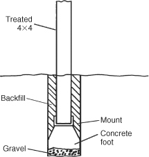
FIGURE 28.22 4 × 4 antenna support.
Even if ground-mounted, full-length λ/4 verticals (35 ft, more or less) for 40 m require guying unless they are made of extremely strong, self-supporting members. A full-size 40-m vertical is akin to a very tall flagpole and requires similar construction unless it is guyed at one or two levels. Even with guying once it is fully vertical, the tubing must be strong enough to not bend or crease while being pulled or pushed up from horizontal to vertical. The problem is even more severe for λ/4 80-m ground-mounted verticals. Irrigation pipe, either butt-joined or telescoped with reducers, is often employed. Antennas of this length require larger ground crews or a cherry picker for successful installation, and the use of techniques covered in Chap. 29 is appropriate.