Searching for an Optimal Schedule
In all the circuits you’ve seen so far in this chapter, the tagged quantum state was specified up front. In this section, you’ll learn to design circuits that tag the optimal solutions for actual application problems even though you don’t know about them when you’re setting up your code.
To illustrate this way of designing circuits, we’ll develop a quantum algorithm to find a valid schedule for Kimmel and Maher performing at the Bellagio. The constraints governing when these stand-up hosts do their acts are listed in A Scheduling Problem, and stated here:
-
Bellagio on Day 1:

-
Bellagio on Day 2:

The qubits ![]() and
and
![]() stand for the comedians
Kimmel and Maher, respectively.
stand for the comedians
Kimmel and Maher, respectively.
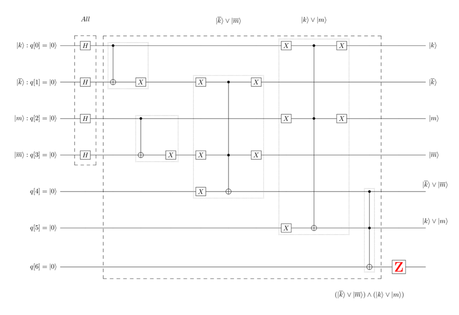
The quantum circuit that models these constraints is explained in Logic Expressions to Quantum Circuit, and shown in the following figure:

You’ll use this set of gates in several places in your program. So we’ll refer to it as Bellagio-Constraint-Gates.
Tagging When You Don’t Know the Optimal Solution
Among the many ways that classical computers differ from quantum computers, one of the most fundamental is the ability of quantum computers to simultaneously hold all possible solutions for the application problem. Whereas in classical computing, the algorithms start with an initial guess and then work up to an optimal solution, Grover’s algorithm takes the reverse tack—starting from all solutions, it whittles away at the mega-qubit to remove non-optimal solutions.
So that the algorithm removes qubelet combinations from the mega-qubit that are non-optimal, you need to differentiate between optimal qubelet combinations—those that satisfy the system of Boolean logic expressions—from non-optimal, those that don’t.
Before the quantum program can get rid of the non-optimal qubelet combinations, you need to first generate all possible qubelet combinations by placing H gates on the variable qubits, as described in Tagging the Optimal Solution, as shown in the following circuit:

The first four qubits, q[0]--q[3], are the
variables ![]() ,
,
![]() ,
,
![]() , and
, and
![]() , respectively.
The H gates are, thus, applied to these
four, as shown in the dashed box on the left in the previous
circuit.
, respectively.
The H gates are, thus, applied to these
four, as shown in the dashed box on the left in the previous
circuit.
Since the H gate splits each of these
four qubits into a pentagon ![]() and
a triangle
and
a triangle ![]() qubelet, the
mega-qubit now contains all 24,
or 16, qubelet combinations, each representing a possible
set of
qubelet, the
mega-qubit now contains all 24,
or 16, qubelet combinations, each representing a possible
set of ![]() and
and ![]() states that satisfies the Boolean logic expressions.
states that satisfies the Boolean logic expressions.
Qubits q[4] and q[5] represent the
contraints for the assignments at the Bellagio on
Days 1 and 2, respectively. These form the control
qubits for the CCNOT gate at the bottom
right in the previous circuit. When a qubelet
combination satisfies these constraints, these
controls are ![]() ,
which, in turn, makes its target,
qubit q[6], switch from
,
which, in turn, makes its target,
qubit q[6], switch from ![]() to
to ![]() .
.
These qubelet combinations—those that make
q[6] ![]() —are
the ones that should be tagged. For the others, at
least one of the constraints will not be met. That
is, one of q[4] or q[5] is
—are
the ones that should be tagged. For the others, at
least one of the constraints will not be met. That
is, one of q[4] or q[5] is
![]() . For these non-optimal
qubelet combinations, the target
qubit, q[6], will remain
. For these non-optimal
qubelet combinations, the target
qubit, q[6], will remain ![]() .
Thus, by applying a Z gate to q[6],
as shown in the following figure, only those qubelet
combinations corresponding to states that satisfy
the Boolean logic expressions will have an inverted triangle
.
Thus, by applying a Z gate to q[6],
as shown in the following figure, only those qubelet
combinations corresponding to states that satisfy
the Boolean logic expressions will have an inverted triangle
![]() qubelet in q[6]:
qubelet in q[6]:
To complete the Tagging Circuit, following the explanation in Why the Second X Gate?, and Disentangling the Bellagio Constraints, you need to hook up quantum gates that mirror the Bellagio Constraints, as shown in the following circuit:

The group of gates in the large dashed box on the left model the Bellagio Constraints. The gates in the large dashed box on the right mirror those in the left and are labeled Bellagio Mirror.
So that the circuit diagrams illustrate the essential structure of Grover’s algorithm, from now on we’ll replace these two groups by blocks, as shown in the following circuit:
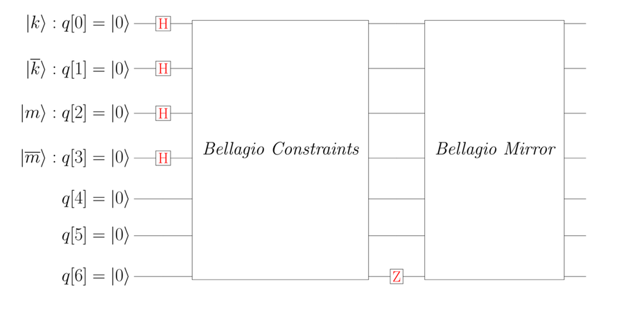
Thus, without knowing what states or qubelet combinations satisfy the Boolean logic expressions, the circuit shown in the previous figure will tag the correct qubelet combinations in the mega-qubit. Next, you’ll design the circuit that removes the non-tagged qubelet combinations—the ones that don’t lead to a valid schedule—from the mega-qubit.
Gates Are Easy to Misplace | |
|---|---|
|
|
In quantum computing you have to be extra careful when placing gates in your circuit. Unlike classical programs, quantum programs have several blocks of code that are similar, making it easy to overlook or misplace a gate. Moreover, since the quantum program deals with multiple qubelet combinations, inserting Measure gates as watch points isn’t helpful. Incorrectly placed gates won’t result in compile-time errors, so debugging gets unnecessarily tedious. One way to mitigate the issue with multiple qubelet combinations in the mega-qubit is to not generate all combinations with the H gate at the beginning. This lets you start with a single state, letting you more easily trace how it changes as it passes through the circuit. |
Completing the Program with the Canceling Circuit
To complete the quantum program, you need to add the Canceling Circuit to the circuit we designed in the previous section. According to the Fundamental Canceling Pattern, the Canceling Circuit is just the Tagging Circuit surrounded by H and X gates, as shown in the following figure:

Before writing a program for this circuit
to obtain the assignment of the talk show hosts,
Kimmel and Maher, to the days they perform at the
Bellagio, first determine the number of iterations
of the Tagging and Canceling
circuits needed. Since there are four primary application
variables in q[0]--q[3], then as stated in
Multiple Iterations, the number
of iterations, ![]() , is given by:
, is given by:

Thus, your final circuit will require another set of the Tagging Circuit followed by the Canceling Circuit. That is, the quantum program will have the following structure:
- H gates on the independent variables to generate all combinations.
- Tagging Circuit for Iteration 1.
- Canceling Circuit for Iteration 1.
- Tagging Circuit for Iteration 2.
- Canceling Circuit for Iteration 2.
The first few lines of the code with two such iterations is listed as follows:
| | // Initialize Quantum and Classical Registers |
| | qreg q[7]; |
| | creg c[2]; |
| | |
| | // Generate All Combinations |
| | h q[0]; |
| | h q[1]; |
| | h q[2]; |
| | h q[3]; |
| | |
| | //// ITERATION 1 |
| | // Constraints (to tag optimal solution) |
| | x q[4]; |
| | x q[5]; |
| | cx q[0],q[1]; |
| | cx q[2],q[3]; |
| | x q[0]; |
| | x q[1]; |
| | x q[3]; |
| | x q[1]; |
| | x q[3]; |
| | ccx q[1],q[3],q[4]; |
| | x q[1]; |
| | x q[2]; |
| | x q[3]; |
| | ccx q[0],q[2],q[5]; |
| | x q[0]; |
| | x q[2]; |
| | ccx q[4],q[5],q[6]; |
| | x q[0]; |
| | x q[2]; |
| | z q[6]; |
(You can get the complete code listing from the book’s page on the Pragmatic Bookshelf’s website at https://pragprog.com/book/nmquantum/quantum-computing.)
The code includes the Measure gates for q[0] and q[2] only, the variables for Kimmel and Maher, respectively. Measure gates aren’t needed for q[1] and q[3], as these are the complements of the ones being measured.
The complete circuit for this code on the IBM Quantum Computer console is shown in the following figure:

The solid vertical line roughly in the center of the figure demarks the two iterations. Each iteration contains the Tagging and Canceling circuits.
When you run this program on the IBM Quantum Computer simulator, you’ll get an output that’s similar to the following chart:
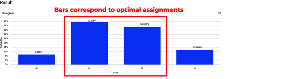
This program collapses to the quantum states associated with the two taller middle bars most frequently—around 75%, or roughly three out of four shots. The labels at the bottom of these bars are 01 on the left bar and 10 on the right bar.
As the states reported by the IBM Quantum Computer
are in the reverse order of the way we denote them,
the left bit on each state represents the
collapse of the ![]() qubit, and
the right bit logs that of the
qubit, and
the right bit logs that of the ![]() qubit.
qubit.
Thus, the taller left bar labeled 01 corresponds to the following solution:

(See Writing a System of Boolean Logic Expressions, where these variables have been defined.)
Likewise, the taller right bar labeled 10 correponds to the following solution:

Limiting our attention to just the Bellagio, these states translate to the following assignments, respectively:
|
|
01 Solution |
10 Solution |
|---|---|---|
|
Day 1 |
Maher |
Kimmel |
|
Day 2 |
Kimmel |
Maher |
Preparing Your Program for Running on a Real Quantum Computer
Before running your program on a real quantum computer, you can do a few things to reduce the effect of noise when computing with real qubits. Specifically, consider the following ways to improve performance:
- Remove Back-to-Back Gates
-
Back-to-back gates leave the state of a qubit unchanged. So removing them has no effect on the final result.
- Use Large Rotations of Qubelets
-
Where possible, rotate qubelets by half turns instead of quarter turns when introducing quantum effects in your code. Larger rotations are less susceptible to noise than rotating qubelets through smaller angles.
- Test for Optimality
-
Despite all your efforts, when you run your quantum program on a real computer, it’s quite likely that the qubits will collapse to incorrect states. Thus, to make it easier to identify which states correspond to optimal solutions and those that don’t, run your states through the quantum gates that model the application’s constraints. That is, before the Measure gates that collapse the qubits, insert the block of gates representing the constraints. Finally, put a Measure gate on the qubit that indicates whether all constraints are met. (For the Bellagio problem, this would be the q[6] qubit.)
Then, on the output, consider as candidates for optimality only the states that have logged a 1 in the corresponding bit. Confirm that they are indeed optimal by plugging their states into constraints set up on a classical computer.