Single Qubit Programs Solutions
Quantum Gates as Matrices Solutions
Solutions for the exercises in Try Your Hand.
-
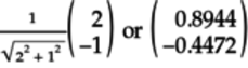
The amplitude
 .
Thus, the probability of the qubit collapsing
to 0 is
.
Thus, the probability of the qubit collapsing
to 0 is
 .
.
The amplitude
 .
So the probability of the qubit collapsing
to 1 is
.
So the probability of the qubit collapsing
to 1 is

The sum of these probabilities is
 .
Since the sum is less than 1,
the vector doesn’t represent a valid
quantum state.
.
Since the sum is less than 1,
the vector doesn’t represent a valid
quantum state.
-
The amplitude
 .
Thus, the probability of the qubit collapsing
to 0 is
.
Thus, the probability of the qubit collapsing
to 0 is
 .
.
The amplitude
 .
So the probability of the qubit collapsing
to 1 is
.
So the probability of the qubit collapsing
to 1 is

The sum of these probabilities is
 .
Since the sum is, for all intents and
purposes, 1,
the vector represents a valid
quantum state.
.
Since the sum is, for all intents and
purposes, 1,
the vector represents a valid
quantum state.
-
-
The qubelets before and after the Z gate are shown here:

The Z gate inverts only the triangle
 qubelet.
-
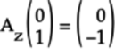
The left qubelet only has a triangle
qubelet. Thus,  .
And the quantum state of the qubit
before the Z gate acts on it is:
.
And the quantum state of the qubit
before the Z gate acts on it is:

After the Z gate acts on the qubit, the triangle
qubelet is inverted. So  .
And the quantum state after the Z gate
acts on it is:
.
And the quantum state after the Z gate
acts on it is:

-
-
The qubelets before and after the H gate acts on the qubit is shown in the following figure:
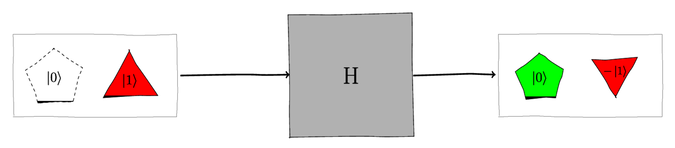
The H gate splits the triangle
qubelet into
a pentagon  qubelet
and an inverted triangle
qubelet.
qubelet
and an inverted triangle
qubelet.
-
The left qubelet only has a triangle
qubelet. Thus, .
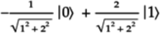
And the quantum state of the qubit
before the H gate acts on it is:

After the H gate acts on the qubit, the triangle
qubelet is split into a pentagon
qubelet and an inverted triangle
qubelet. The amplitudes are:

Wrting the amplitudes in vector form, we get:

-
-
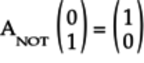
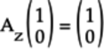
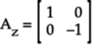
The operation is:

-
The first column of the
 matrix is:

-
-
The operation is:
-
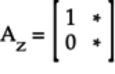
The complete
matrix is:

-
-
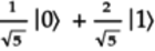
This qubit has two pentagon
qubelets and one inverted triangle
qubelet. Thus, its normalized quantum state is:
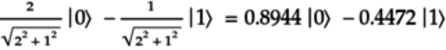
The negative sign for the amplitude associated with
indicates that the
triangle qubelet is inverted.
The vector for this quantum state is:
The probabilities of the qubit collapsing to 0 and 1 are:

-
When the NOT gate acts on the qubit with two pentagon
qubelets and an inverted triangle
qubelet, it switches the two pentagon qubelets
to two triangle qubelets,
and it switches the inverted triangle
qubelet to an inverted pentagon qubelet,
as shown in the following figure:

The normalized quantum state of the blended qubit on the right is:
(Note the inverted pentagon
qubelet drawn on the right of the right qubit.
This placement reflects that the NOT
gate switched the inverted triangle
qubelet in the left qubit.)
Writing this quantum state in vector form, we get:

The probabilities of the qubit collapsing to 0 and 1 are:

The probabilities of the qubit collapsing to 0 and 1, respectively, get switched after the NOT gate acts on the qubit. In other words, when a NOT gate acts on a blended qubit, the probabilities of collapsing to the classical states 0 or 1 are switched.
-
To calculate the quantum state of the qubit after the NOT gate acts on it, multiply the
matrix by the vector for the initial
quantum state as follows:

This quantum state is identical to the one obtained by analyzing the NOT gate operation using qubelets.
-
-
The operation is:
-
The first column of the
 matrix is:
-
-
The operation is:
-
The complete
matrix is:
-
-
This qubit has one pentagon
qubelet and two inverted triangle
qubelets. Thus, it’s normalized quantum state is:

The negative size for the amplitude associated with
indicates that the triangle qubelet is inverted.
The vector for this quantum state is:

-
When the Z gate acts on the qubit with one pentagon
qubelet and two inverted triangle
qubelets, it’ll leave the pentagon qubelet alone but
will switch the triangle qubelets, as shown in the
following figure:
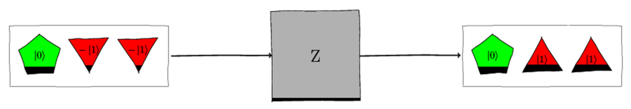
The normalized quantum state of the blended qubit on the right is:
Writing this quantum state in vector form, we get:

-
To calculate the quantum state of the qubit after the Z gate acts on it, multiply the
matrix by the vector for the initial
quantum state, as follows:
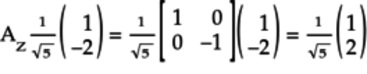
This quantum state is identical to the one obtained by analyzing the Z gate operation using qubelets.
-
Gate Matrix Restrictions Solutions
Solutions for the exercises in Try Your Hand.
-
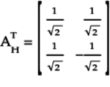
To determine the Hermitian matrix, first get its transpose,
 , by switching
the matrix’s rows and columns:
, by switching
the matrix’s rows and columns:

Next, replace each element with its complex conjugate:

-
To check if this matrix represents a quantum gate, first calculate the product matrix,
 :
:

To multiply these matrices, we’ll use the method described in Multiplying Matrices. According to this method, we’ll get the product matrix by working out each column of the product individually. The first column of the product matrix is:

The second column of the product is:

Arrange these columns to get the product:
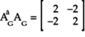
Since the product
isn’t
the identity matrix,
 isn’t a valid quantum
gate matrix.
isn’t a valid quantum
gate matrix.
-
-
To determine the Hermitian matrix, first get its transpose,
 ,
by switching the matrix’s rows and columns:
,
by switching the matrix’s rows and columns:

Next, replace each element with its complex conjugate:
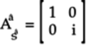
This matrix for the
 gate
is identical to the
gate
is identical to the  matrix for the
  gate.
gate.
-
To see if this matrix represents a quantum gate, first calculate the product matrix,
 :
:
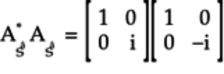
To multiply these matrices, we’ll use the method described in Multiplying Matrices. According to this method, we’ll get the product matrix by working out each column of the product individually. The first column of the product matrix is:

The second column of the product matrix is:

Arrange these columns to get the product:

Since the product is the identity matrix, it represents a quantum gate. In fact, the
gate is one of the
predefined gates in the IBM Quantum Computer.
-
-
To determine the Hermitian matrix, first get its transpose,
 , by
switching the matrix’s rows and columns:
, by
switching the matrix’s rows and columns:
Since each element of the matrix is real, this matrix is the conjugate transpose. In other words,

-
To see if this matrix represents a quantum gate, first calculate the product matrix
 :
:

To multiply these matrices, we’ll use the method described in Multiplying Matrices. According to this method, we’ll get the product matrix by working out each column of the product individually. The first column of the product matrix is:

The second column of the product matrix is:

Arrange these columns to get the product:
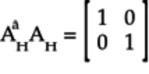
Since this product is the identity matrix, the
 matrix represents
the H gate.
matrix represents
the H gate.
-
-
To get the
 matrix for
 ,
set
,
set  ,
,  , and
, and
 :
:

Noting that
 ,
,
 , the
above matrix simplifies to:
, the
above matrix simplifies to:
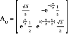
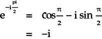
Using Euler’s formula:

And,

Substituting these terms back in the matrix
 :
:

-
To determine the Hermitian matrix, first get its transpose:

Next, replace each element of the matrix with its conjugate:

-
To check if the
matrix is
unitary, first calculate the product matrix
 :
:
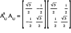
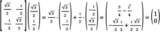
To multiply these matrices, we’ll use the method described in Multiplying Matrices. According to this method, we’ll get the product matrix by working out each column of the product individually. The first column of the product matrix is:
The second column of the product matrix is:
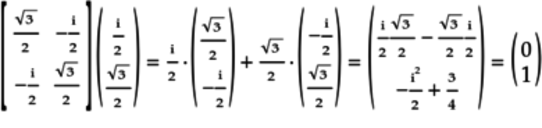
Arrange these columns to get the product:

Since the product is the identity matrix, matrix
is unitary.
-
To determine the parameters for the Universal gate,
 , associated with
 , equate the
matrix with that of
:
, equate the
matrix with that of
:

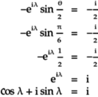
The idea in these types of matrix equations is to compare the respective elements in the matrix on the left to the one on the right. Start with the element on the right that has the fewest parameters. Thus, looking at the top left element from both matrices:

Next, equate the bottom left (second row, first column) elements in both matrices:

Since the imaginary part on the right is
 ,
the imaginary part on the left,
,
the imaginary part on the left,  ,
must also be . The smallest such
angle is 270° or:
,
must also be . The smallest such
angle is 270° or:

This value also makes the real part,
 .
.
Finally, to compute
 ,
compare the top right (first row, second column)
terms from both matrices:
,
compare the top right (first row, second column)
terms from both matrices:
Since the real part on the right is 0, the real part on the left,
 ,
is also 0:
,
is also 0:
A quick check confirms that this value of
makes the imaginary part on the right,
 ,
equal to 1 as required.
,
equal to 1 as required.
Note that we only needed three of the four element comparisons to get the three parameters for the
gate. You can verify,
though, that these three values correctly equate to the
fourth element on the bottom right of the right matrix
stated earlier.
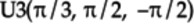
The Universal gate that implements the
matrix is
 .
.
-
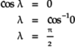
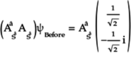
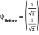
To compute the quantum state when the
 gate acts on the
qubit, calculate the following:
gate acts on the
qubit, calculate the following:
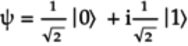
Or, writing the quantum state as an equation:

-
To compute the probabilities of the qubit collapsing to the idealized states, take the squares of the amplitudes but use the conjugate complexes, as explained in Measuring Magnitudes of Complex Numbers:

And,

-
The quantum program is listed here:
qreg q[1]; creg c[1]; u3(pi/3,pi/2,-pi/2) q[0]; measure q[0] -> c[0]; -
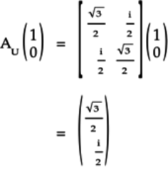
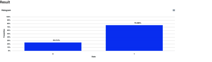
The output of this program is shown in the following figure:

Yes, the likelihoods of finding 0 or 1 in the classical registers is roughly 75% or 25%, respectively. These match the probabilities of the q[0] qubit collapsing to
or , respectively,
as calculated earlier.
-
-
The quantum program for the circuit with back-to-back Universal gates is listed here:
1: qreg q[1]; 2: creg c[1]; 3: 4: u3(pi/3,pi/2,-pi/2) q[0]; 5: u3(pi/3,3*pi/2,pi/2) q[0]; 6: measure q[0] -> c[0]; The
gate is
declared on line 5.
-
The output of this program is shown in the following figure:

The
gate
restores the quantum state of the q[0] back to
. In other words, since this gate
is the Hermitian matrix of the
gate, it reverses the action on the
qubit and puts it back to the original state before
these gates acted on it.
Thus, the concept of back-to-back gates defined by matrices that are
Hermitians of each other is similar to what you saw
earlier in
Back-to-Back H Gates: The First Hint of Taming Randomness.
-
-
The quantum program for this circuit is as follows:
qreg q[1]; creg c[1]; u3(pi/3,pi/2,-pi/2) q[0]; u3(pi/3,pi/4,-pi/2) q[0]; measure q[0] -> c[0]; -
The output of this program is shown here:
In this case, the q[0] qubit isn’t restored to its original
state as in the previous part. Both U3 gates
have the same  , which determines the
numbers of pentagon and triangle
qubelets in the quantum state,
and the same
, which determines the
numbers of pentagon and triangle
qubelets in the quantum state,
and the same  .
But they have different values for the
second parameter,
.
But they have different values for the
second parameter,  , which measures
the relative difference between the orientations
of the pentagon and triangle
qubelets.
Because the second U3 gate’s
angle doesn’t exactly “twist back”
the effect of the first gate on the qubelets, the
quantum state isn’t restored. Hence, the qubit doesn’t
go back to after the second
U3 gate and remains in a
blended state. When this blended
qubit is measured, it collapses to either
or . As a result, the classical
register records both the 0 and 1 states.
, which measures
the relative difference between the orientations
of the pentagon and triangle
qubelets.
Because the second U3 gate’s
angle doesn’t exactly “twist back”
the effect of the first gate on the qubelets, the
quantum state isn’t restored. Hence, the qubit doesn’t
go back to after the second
U3 gate and remains in a
blended state. When this blended
qubit is measured, it collapses to either
or . As a result, the classical
register records both the 0 and 1 states.
-
-
-
Let
 be the quantum state of the qubit
before it’s acted on by the
be the quantum state of the qubit
before it’s acted on by the  gate.
Then, the following matrix
equation defines how the
gates modifies this quantum state:
gate.
Then, the following matrix
equation defines how the
gates modifies this quantum state:

To get
, pre-multiply both sides
by the  matrix’s Hermitian,
 :
:
Note that
 . Thus,
 ,
the identity matrix.
As a result, the left-hand side simplifies to .
After substituting for
,
the identity matrix.
As a result, the left-hand side simplifies to .
After substituting for  on the right-hand side, the above equation reduces to:

Thus, the original quantum state before the
gate operates on it is:
Analyzing Quantum Gate Matrices Solutions
Solutions for the exercises in Try Your Hand.
-
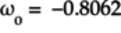
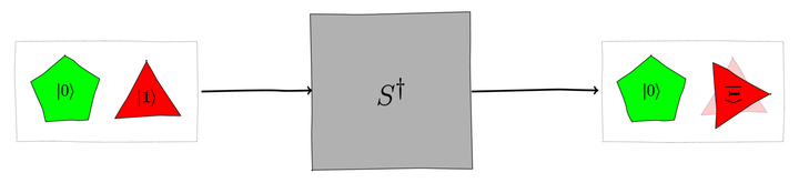
The equation for the given quantum state,
 , is:
, is:
Compare this equation with that of the general quantum state:

The
 term injects the
complex number into the equation for the
state. To determine the value of ,
relate the corresponding
terms in the general equation with that of the
given quantum state :
term injects the
complex number into the equation for the
state. To determine the value of ,
relate the corresponding
terms in the general equation with that of the
given quantum state :

The real term,
 , must be
0 since the right-hand side is a pure complex number:
, must be
0 since the right-hand side is a pure complex number:
Further,
 confirms that the calculations for are
right.
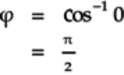
Thus, the angle , the relative difference
between the orientations of the pentagon
and triangle qubelets, is
90°.
confirms that the calculations for are
right.
Thus, the angle , the relative difference
between the orientations of the pentagon
and triangle qubelets, is
90°.
To calculate
 , the angle which the
quantum state vector leans away from the vertical
on the Bloch sphere, compare the amplitudes for
and
in the general equation for the quantum state with
that for :
, the angle which the
quantum state vector leans away from the vertical
on the Bloch sphere, compare the amplitudes for
and
in the general equation for the quantum state with
that for :

Calculate
from the amplitude for
as follows:

Setting
in the
amplitude for ,
 , gives
  ,
validating that our calculations are correct.
,
validating that our calculations are correct.
Thus, the parameters for the
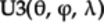 gate are:
Since we are working on
,
we only need to look at the first column of the
gate matrix for U3 which doesn’t rely on
. So, any value of
can be used as it’ll not affect the behavior of the
gate on .
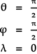
Recall from Number of Qubelets Define the Amplitudes, the number of pentagon
and triangle qubelets in the qubit
are related as follows:

These parameters for the
gate
puts the qubit in the
quantum state having an equal number
of pentagon and triangle
qubelets, with the
triangle qubelets rotated
90° anticlockwise, as shown in the following figure:
This quantum state is identical to the one worked out in the previous section using the qubelets approach.
The probabilities of the qubit collapsing to
or ,
respectively, is the “square” of the amplitudes:

Notice that to compute the probability of collapsing to
, the amplitude
is a complex number, so we multiply by its
complex conjugate.
-
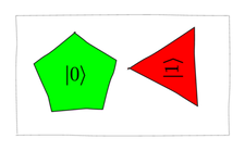
The quantum circuit is shown here:
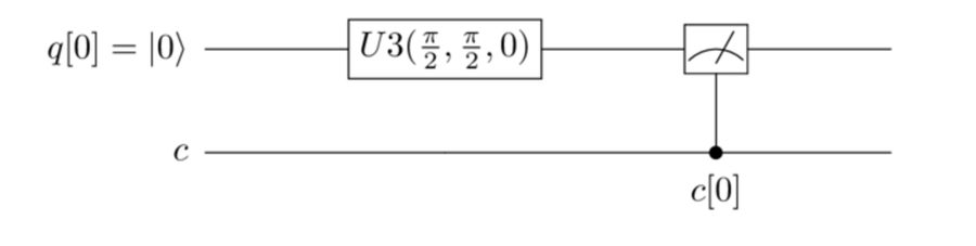
The quantum program is the following:
qreg q[1]; creg c[1]; u3(pi/2,pi/2,0) q[0]; measure q[0] -> c[0]; The output of this program is shown in the following figure:
The classical registers won’t log the angles of the pentagon
and triangle
qubelets. But the classical
states recorded match the probabilities of the qubit
collapsing to or
, respectively, calculated
in the previous part.
-
The quantum program is as follows:
qreg q[1]; creg c[1]; u3(pi/2,pi/2,0) q[0]; s q[0]; measure q[0] -> c[0]; The output of this program is shown.
Since the S gate only rotates the pentagon
qubelets but doesn’t split any
qubelets, the relative number of pentagon
and qubelets remains the same.
Consequently, the probabilities of the qubit collapsing to
or
don’t change and, hence, the classical states recorded
in the classical registers will also be similar to what
was recorded in the previous part.
-
No, you can’t confirm whether the pentagon
qubelets are rotated
since the gates didn’t change the relative number
of pentagon and
triangle qubelets.
(In later sections you’ll learn to write programs
that validate the qubelet rotations.)
-
-
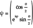
The vector for the general quantum state
is:
The
parameter, which measures the
relative difference in orientations between the
pentagon and the
triangle qubelets,
is associated with the triangle
qubelets. Thus, turning both qubelets
by the same angle doesn’t change the quantum state.
Redraw the qubit on the right so that
the pentagon
qubelet is rotated back to the non-rotated state by
turning both qubelets 90° clockwise, as
shown in the following figure:

The required gate leaves the pentagon
qubelet alone. Thus,
the top left element of the gate’s matrix must be
1:

The
 indicates that those corresponding
terms aren’t yet known.
indicates that those corresponding
terms aren’t yet known.
This gate doesn’t take a qubelet of one type and change it to the other type by splitting or switching the qubelet. As a result, the non-diagonal terms in the gate’s matrix are 0:

(If the gate were to split qubelets, for example, then the non-diagonal terms would be nonzero.)
The triangle
qubelet is rotated 90° clockwise.
This rotation is governed by the following
equation:

Substitute
 for
(the sign is negative because the rotation is
clockwise):
for
(the sign is negative because the rotation is
clockwise):
Thus, the gate matrix is:

Since this matrix must be Hermitian for a quantum gate, you can confirm that something is 1. Hence, this matrix matches that of the
gate.
Although this problem is ostensibly about rotating a pentagon
qubelet, it’s actually equivalent to rotating the
triangle qubelet.
Solutions: Quantum Gates and How to Use Them
Solutions for the exercises in Try Your Hand.
-
False. The Y gate switches and rotates qubelets. That is, when it acts on, say, a triangle
qubelet, it’ll switch it to a pentagon
qubelet and
rotate it. But it won’t split qubelets.
Hence, it doesn’t take an idealized quantum
state and put it in a blended
state.
-
False. Both the
and
T gates leave the
qubelets alone but rotate the triangle
qubelets. So they’ll have no effect on the
qubit but will rotate the triangle
qubelets in the qubit.
-
True. The S gate rotates the triangle
qubelets
90°, or a quarter turn anticlockwise.
The  gate rotates the
triangle qubelets
45°, or a
one-eighth
turn clockwise. Both leave the
pentagon qubelets
alone. Thus, two gates
rotate the triangle
qubelets by 90°, or a quarter turn
clockwise, reversing the action of the
S gate.
gate rotates the
triangle qubelets
45°, or a
one-eighth
turn clockwise. Both leave the
pentagon qubelets
alone. Thus, two gates
rotate the triangle
qubelets by 90°, or a quarter turn
clockwise, reversing the action of the
S gate.
-
True. The S gate rotates the triangle
qubelets
90°, or a quarter turn anticlockwise.
The T gate rotates the triangle
qubelets by
45°, or a one-eighth
turn anticlockwise. Thus, when both gates operate on the
triangle qubelets,
the total rotation is 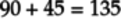 °
anticlockwise.
°
anticlockwise.
-
True. The
 gate splits
qubelets like the H gate, although
asymmetrically. Nonetheless, it puts an idealized
qubit, or ,
into a blended state.
gate splits
qubelets like the H gate, although
asymmetrically. Nonetheless, it puts an idealized
qubit, or ,
into a blended state.
-
-
The quantum state after the Y gate acts on the
qubit is
shown in the following figure:

-
If the NOT (X) gate were to act on the
qubit,
the pentagon qubit
would be switched to a triangle
qubit but wouldn’t be rotated, as shown in the next figure:
-
Regardless of how the triangle
qubelet is rotated, it’ll always collapse to the
idealized qubit, which
logs a 1 in the classical register.
Thus, in both cases, the outputs will be
identical.
-
-
As each gate acts on the
qubit, it affects the qubelets as follows:
- First X Gate
-
Switches the
qubit
to . The
qubit will contain only a triangle
qubelet.
- T Gate
-
Rotates the triangle
qubelet by 45°, or a one-eighth
turn anticlockwise.
- Second X Gate
-
Switches the
qubit to
. The 45°-rotated triangle
qubelet is switched to a 45°-rotated
pentagon qubelet.
The action of these three gates is summarized in the following figure:

Thus, this circuit rotates the pentagon
qubelet.
-
The program for this circuit is as follows:
qreg q[1]; creg c[1]; h q[0]; sdg q[0]; h q[0]; measure q[0] -> c[0]; -
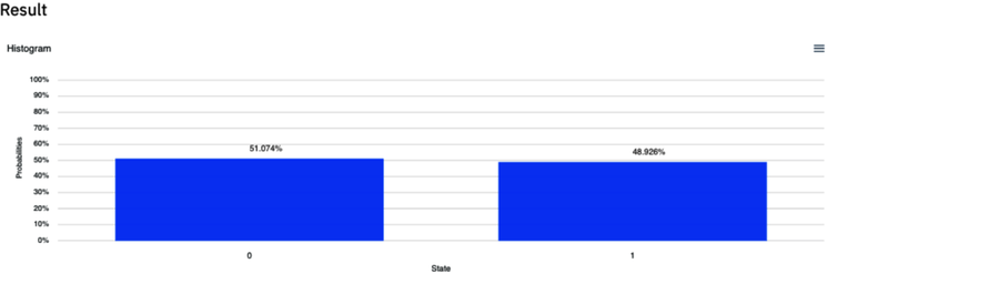
The output of this program is shown in the following figure:

The output shows a 0 or 1 logged in the classical register with about the same probabilities. This distribution indicates that the q[0] qubit collapses about equally to the idealized qubits,
or . This suggests
that the q[0] qubit was in a
blended state before it was
collapsed by the Measure gate.
Had the second H gate reversed
the effect of the first H gate,
the q[0] qubit would be put back to
.
The reason why the second H gate, despite being its own adjoint, doesn’t reverse the effect of the first H gate on the qubit is that the
gate spins the triangle
qubelets by –90°, or a quarter turn clockwise.
As a direct result of this extra rotation, the
triangle qubelets are
no longer aligned with the pentagon
qubelets, as shown in the following figure:
When the right qubit gets split by the second H gate, the triangle
qubelets can’t cancel out, thereby leaving the qubit in a
blended state, as shown in the next figure:

This is the first time you’re seeing a quantum state where the qubelets of the same type have different angles. In the next section, you’ll learn how to deal with such quantum states. For now, it’s enough to recognize that the triangle
qubelets can’t cancel out to give an idealized state.
Thus, the qubit remains in a blended state.
-
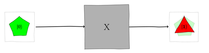
The quantum program for this circuit is listed as follows:
qreg q[1]; creg c[1]; h q[0]; sdg q[0]; » s q[0]; h q[0]; measure q[0] -> c[0]; This program is the same as that in the previous part other than declaring the S gate as highlighted.
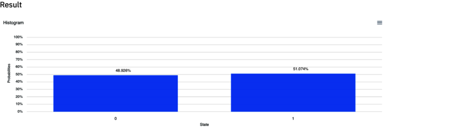
You should get an output for this program that is similar to the one shown.
This time, the classical register only logs 0, indicating that the second H gate successfully put the q[0] qubit in its original idealized state,
. The reason
for this is that the S gate
spun the triangle
qubelets back by 90°, or a quarter
turn anticlockwise, and aligned them. As a
result, the second H gate
could cancel out the triangle
qubelets from the quantum state.

-
-
The code listing for this circuit is as follows:
qreg q[1]; creg c[1]; rx(pi/3) q[0]; measure q[0] -> c[0]; -
The vector for the
qubit in q[0] is:

Thus, the quantum state
 after the
  acts on the
qubit is:
acts on the
qubit is:

-
The vector for
is:
Thus, the ratio of pentagon
to triangle qubelets is
 .
.
-
To get the angles of rotation of the qubelets, compare the vector for
with that
for the general quantum state.
Thus, the pentagon qubelets
aren’t rotated, but the triangle
qubelets are rotated by --90°, or a quarter
turn clockwise.
-
Probability of
collapsing to the idealized states is the
squares of their respective amplitudes.
Thus, the probability of
collapsing to is:

Similarly, the probability of
collapsing to is:

Because the amplitude for
is a complex number, we multiply it by its
complex conjugate instead of directly squaring
it.
-
The output of running this program should be similar to the following figure:

The probabilities of recording the 0 and 1 bits in the classical register, about 75% and 25%, respectively, match those calculated in the previous part.
-
Sequence of Gates as Matrix Multiplication Solutions
Solutions for the exercises in Try Your Hand.
-
No. The correct way to multiply the gate matrices is:

The gate matrices are written in the reverse direction from the order in which the gates act on the qubit.
-
Yes. The
 gate reverses the
action of the T gate so, in effect,
the qubit isn’t affected by those gates.
In terms of matrices, the
gate reverses the
action of the T gate so, in effect,
the qubit isn’t affected by those gates.
In terms of matrices, the  state is calculated as follows:
Note that
 is the Hermitian
of
is the Hermitian
of  . So,
. So,  , resulting
in the simplification of the previous equation.
, resulting
in the simplification of the previous equation.
-
Yes. The Hermitian of the
matrix,  , is
just . So the given matrix multiplication
works out as follows:
, is
just . So the given matrix multiplication
works out as follows:

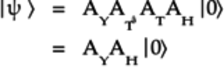
This equation represents the circuit in which the H gate first acts on the
qubit followed by the S gate, as
shown in the figure for this part.
-
Yes. The S gate rotates the triangle
qubelets
by a quarter turn anticlockwise. The
gate then rotates the
triangle qubelets
a one-eighth
turn clockwise. Thus, the net rotation of the triangle
qubelets is a
one-eighth turn
anticlockwise. This rotation corresponds to just
applying the T gate in place of the
S and gates.
We can also show this mathematically in terms of matrices. Start with the following equation, which directly uses the gate matrices as the gates appear in the circuit but in the reverse order:

Next, recognize that the
matrix
is the square root of the
matrix. Thus, replace
with  in the previous equation:

The last equation was simplified by noticing that
 .
.
-
Yes. The matrix multiplications for this sequence of gates to compute the final state
is:

Writing out the actual gate matrices for the H and Z gates, the previous equation becomes:
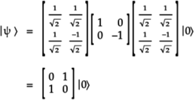
The matrix in the previous equation corresponds to the NOT (X) gate. Thus, the final quantum state can be written as:

-
-
No. This circuit won’t return anything since the qubit isn’t collapsed.
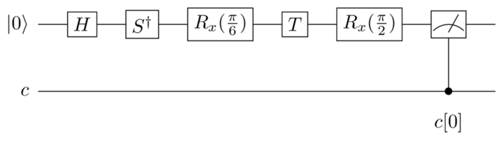
To get this circuit to run on a quantum computer, add a classical register and a Measure gate, as shown in the following figure:
-
The quantum program for the circuit in the previous part is listed here:
qreg q[1]; creg c[1]; h q[0]; sdg q[0]; rx(pi/6) q[0]; t q[0]; rx(pi/2) q[0]; measure q[0] -> c[0]; -
The probabilities of the qubit collapsing to the idealized states are calculated by multiplying the respective amplitudes by their conjugate complexes as follows:

And,
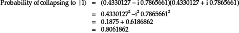
As an additional check, these probabilities add up to 1, indicating that the qubit collapses to either one of these two idealized states.
-
The output of running this program should be similar to the following figure:

The probabilities of recording 0 and 1 bits in the classical register, about 23% and 76%, respectively, match those calculated in the previous part.
-
-
The quantum state
is:

-
The quantum state vector in the Visualizations tab is identical to what’s calculated in the previous part.
-
The probabilities of the qubit collapsing to the idealized states are calculated by multiplying the respective amplitudes by their complex conjugates as follows:

And,

-
The code listing for this circuit is the following:
qreg q[1]; creg c[1]; h q[0]; s q[0]; h q[0]; measure q[0] -> c[0]; -
The output of running this program should be similar to the following figure:

The probabilities of recording 0 and 1 bits in the classical register, each about 50%, match those calculated in earlier.
-