Multi-Qubit Programs Solutions
Solutions for the exercises in Try Your Hand.
-
The amplitude for
 is the second element of the vector:

-
The amplitude for
 is the first element of the vector:

-
-
No. The columns of a matrix for a quantum gate correspond to the idealized states. The number of idealized states is a power of 2. Since 3 is not a power of 2, a
 matrix can’t be a quantum gate
matrix.
matrix can’t be a quantum gate
matrix.
-
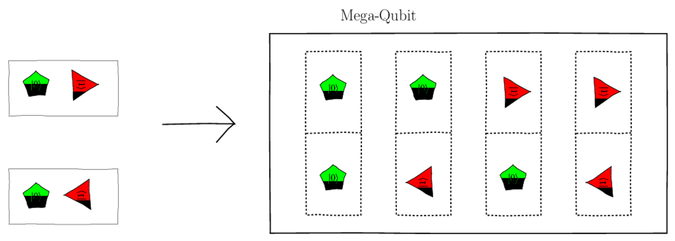
The correct expression is c. This is a single qubit with two pentagon
 qubelets
and a single triangle
qubelets
and a single triangle  qubelet rotated a quarter turn anticlockwise.
Thus, the correct way to express it is:
qubelet rotated a quarter turn anticlockwise.
Thus, the correct way to express it is:
-
Probability of collapsing to each of the four idealized states is calculated in the following table:
Idealized State
Amplitude
Conjugate of Amplitude
Probability of Collapsing


-
For the classical register to record a 1 when you collapse the second qubit means that the quantum state had to collapse to either a
or a
state. Thus, from the probabilities calculated in the
previous part, the probability of logging a 1
is:

-
Yes, the quantum state of the system will change.
Since the second qubit collapses to
,
the new state of the system can only have the
and states.
These must be normalized as follows to get the new
state,  :
:
In other words,
 ,
and the state before and after the measurement of the
second qubit are different.
,
and the state before and after the measurement of the
second qubit are different.
This example shows that the act of measuring a qubit changes the state of the system. This effect, in fact, is a key defining feature of quantum mechanics and underpins Heisenberg’s uncertainty principle.[119]
Thus, if you arbitrarily place Measure gates in your code to help you see whether it’s behaving as expected, you’ll end up actually destroying the effect you’re trying to see.
-
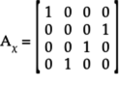
-
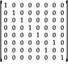
This matrix describes a quantum operation that is like a
 gate as shown by the following circuit:
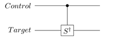
When the control qubit is
,
any pentagon qubelets in the
target qubit’s state are left alone
but the triangle qubelets
are given a quarter turn clockwise.
-
Since this gate works on three qubits, its gate matrix’s dimensions will be
 .
.
-
The quantum states on the bottom two qubits are swapped only when
 is . That is,
Specifically, only the following states are affected by this gate:
Even though the control qubit is
in  and
and  , swapping the second and
third states doesn’t change the overall quantum state.
For all other cases, the control qubit
is , and hence, the gate doesn’t
modify any of those states. Thus, the gate matrix is:
, swapping the second and
third states doesn’t change the overall quantum state.
For all other cases, the control qubit
is , and hence, the gate doesn’t
modify any of those states. Thus, the gate matrix is:
-
-
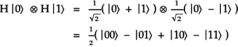
Since this circuit has two qubits, it’ll have a
 gate matrix. To obtain
the gate matrix, recall that the H
gate splits the and
qubits as follows:
gate matrix. To obtain
the gate matrix, recall that the H
gate splits the and
qubits as follows:
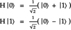
In these equations,
 and
and
 are the actions of the
H gate on the
and qubits, respectively.
are the actions of the
H gate on the
and qubits, respectively.
Now, work out what this circuit does to each of the four idealized states,
,
, ,
and :
- Idealized State:
-
Both the top and bottom H gates split the
qubit.
Thus, the mega-qubit formed by this idealized state is:
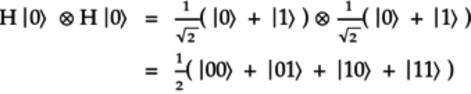
This state corresponds to the following vector:

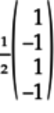
- Idealized State:
-
The top H gate splits the
qubit, and the
bottom H gate splits the
qubit.
Thus, the mega-qubit formed by this idealized state is:
This state corresponds to the following vector:
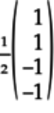
- Idealized State:
-
The top H gate splits the
qubit, and the
bottom H gate splits the
qubit.
Thus, the mega-qubit formed by this idealized state is:
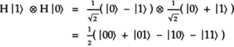
This state corresponds to the following vector:
- Idealized State:
-
Both the top and bottom H gates split the
qubit.
Thus, the mega-qubit formed by this idealized state is:

This state corresponds to the following vector:
The previous four vectors correspond to the columns of the matrix representing this circuit:

-
While the S gate rotates triangle
qubelets a quarter
turn anticlockwise, the  gate
rotates the triangle
qubelets clockwise. Both gates
leave pentagon
qubelets alone.
gate
rotates the triangle
qubelets clockwise. Both gates
leave pentagon
qubelets alone.
Thus, to obtain the gate matrix for the given circuit, replace
 with
with  :
:

-
-
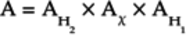
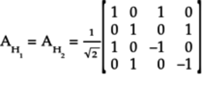
To calculate the matrix for this circuit, start by breaking it up as shown in the following figure:
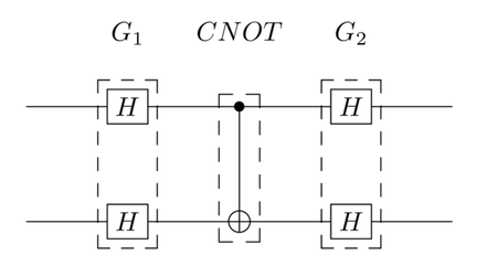
Then the matrix
 for the entire circuit
is calculated as follows:
for the entire circuit
is calculated as follows:

 is the matrix for the
CNOT gate.
is the matrix for the
CNOT gate.  and
and  are the matrices for
the part of the circuit where each qubit is
operated on by an H gate, respectively.
are the matrices for
the part of the circuit where each qubit is
operated on by an H gate, respectively.
The matrix for the CNOT gate is:
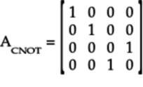
The
and
matrices were obtained in the previous
part. That is,

Thus, the matrix
for the entire
circuit is:
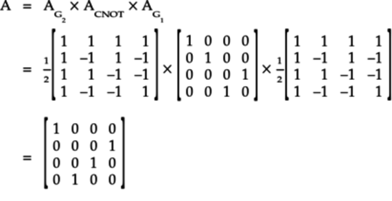
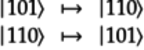
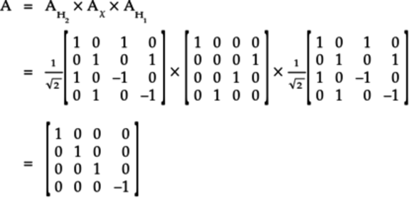
This circuit, then, modifies the idealized states as follows:
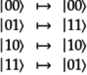
It leaves the
and
states alone but
affects the and
states. Specifically,
when the second qubit is ,
it switches the first qubit.
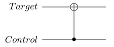
This circuit acts like an upside down CNOT gate where the first qubit is the target and the second qubit is the control, as shown here:
-
To calculate the matrix for this circuit, start by breaking it up as shown in the following figure:
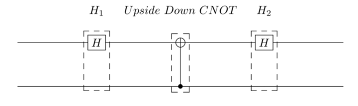
Thus, the matrix
for the entire
circuit can be calculated as follows:
 is the matrix for the
upside down CNOT gate
calculated in the previous part:
is the matrix for the
upside down CNOT gate
calculated in the previous part:
The
 and
and  are the matrices for the pass-through
H gate. This matrix was calculated
in Working with Blended States: Mega-Qubit as a Tensor:
are the matrices for the pass-through
H gate. This matrix was calculated
in Working with Blended States: Mega-Qubit as a Tensor:
Thus, the matrix
for the entire
circuit is:
This is the matrix for the Control Z gate shown in the following figure:
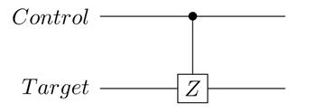
This gate leaves the
,
, and
alone but inverts the triangle
qubelets in the target qubit if the
control qubit is .
That is:
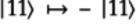
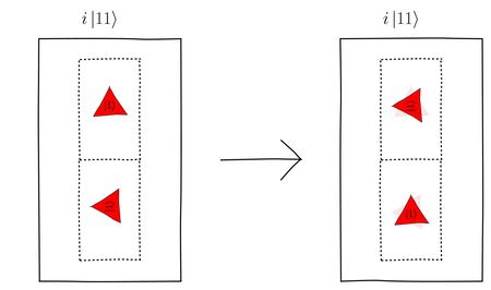
-
-
The triangle
qubelet in the bottom cell of the qubelet
combination on the left is rotated 90°
anticlockwise but non-inverted in the bottom
cell of that on the right. That is, the
bottom triangle
qubelet on the left is rotated 90°
clockwise on the right. So for the qubelet
combination on the right to have the same
quantum state as that on the left, the
top triangle qubelet
in the right combination must be rotated
90° anticlockwise, as shown in the following
figure:
-
The triangle
qubelet in the bottom cell of the qubelet
combination on the left is inverted but
non-inverted in the bottom cell of that on the
right. So that the right combination has the
same quantum state as that on the left, the
triangle qubelet in
the top cell of the left combination is
given a 180° rotation, as shown in the
following figure:

-
-
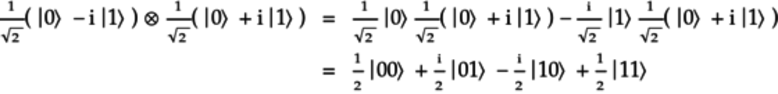
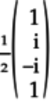
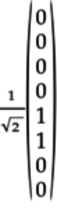
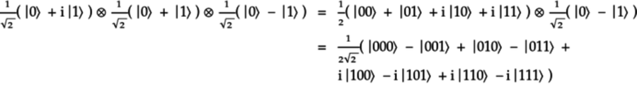
Expand the tensor product to get the quantum state as follows:

This corresponds to a quantum state vector having
 elements. All
the elements are
elements. All
the elements are  except its
twenty-third element which is
except its
twenty-third element which is
 .
.
The associated mega-qubit is:

The mega-qubit contains just a single qubelet combination. Thus, even an idealized state can be expressed as a tensor product.
-
Expand the tensor product to get the quantum state, as follows:

This corresponds to the following vector:

The associated mega-qubit is shown in the figure.

The triangle
qubelet in the
second qubelet combination is rotated 90°
due to the amplitude of being
.
-
Expand the tensor product to get the quantum state as follows:
This corresponds to the following vector:
The associated mega-qubit is the following:
The anticlockwise quarter-turn triangle
qubelet in the second
qubelet combination contributes  to its amplitude coefficent. That is,
  .
Likewise, the clockwise quarter-turn triangle
qubelet in the third qubelet
combination contributes
.
Likewise, the clockwise quarter-turn triangle
qubelet in the third qubelet
combination contributes  to
its amplitude coefficient. That is,
to
its amplitude coefficient. That is,  .
.
In the last qubelet combination, top triangle
qubelet contributes
and the bottom triangle
qubelet contributes
 . That is, the overall
amplitude coefficient is the product of these
terms:
. That is, the overall
amplitude coefficient is the product of these
terms:  . In
other words, the fourth qubelet combination is
equivalent to one where both triangle
qubelets are not
rotated. You can also see this by giving
both qubelets the same rotation but in opposite
directions so that any sign changes are canceled
out: rotate the top triangle
qubelet a quarter turn anticlockwise and the bottom
triangle qubelet a quarter
turn clockwise.
. In
other words, the fourth qubelet combination is
equivalent to one where both triangle
qubelets are not
rotated. You can also see this by giving
both qubelets the same rotation but in opposite
directions so that any sign changes are canceled
out: rotate the top triangle
qubelet a quarter turn anticlockwise and the bottom
triangle qubelet a quarter
turn clockwise.
Thus, the mega-qubit can also be drawn as in the following figure:

In this figure, the fourth qubelet combination has non-rotated triangle
qubelets.
-
The H gate splits the
qubit, and the X gate switches the
qubit as follows::

Thus, the given tensor product is:

Expand this tensor product to get the quantum state as follows:
This corresponds to the following vector:
This
 vector has a
in the fifth
and sixth positions, and
elsewhere.
vector has a
in the fifth
and sixth positions, and
elsewhere.
The associated mega-qubit is:

-
-
To see whether the two qubits are entangled, try factoring the quantum state as follows:
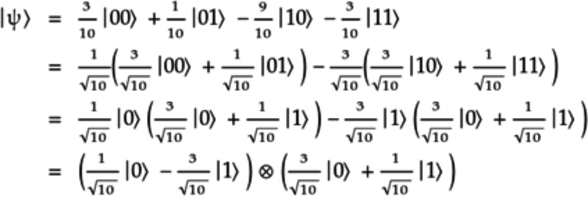
This quantum state can be factored as the tensor product of two quantum states. Hence, the qubits are not entangled.
-
The given quantum state can’t be factored as a product of tensor products. Hence, the qubits are entangled.
You can also directly see this from the quantum state itself. If the first qubit collapses to, say,
, then the quantum
state has collapsed to .
Thus, the second qubit is forced to collapse to
. An analogous result
holds if the first qubit collapses to .
Furthermore, you’ll see the same behavior had you
collapsed the second qubit before the first.
-
-
To identify the three missing qubelets, first expand the tensor product of the three qubits to obtain the quantum state of the mega-qubit, as follows:
The missing qubelet is in the bottom cell of the fourth qubelet combination which corresponds to the
 term in the quantum
state specified in the above equation. This combination
is formed by taking the pentagon
qubelet from the top qubit, the triangle
qubelet from the middle qubit, and the inverted triangle
qubit from the bottom qubit.
The inverted qubelet gives the negative sign associated
with this combination. Thus, the first missing qubelet
is an inverted triangle qubelet.
term in the quantum
state specified in the above equation. This combination
is formed by taking the pentagon
qubelet from the top qubit, the triangle
qubelet from the middle qubit, and the inverted triangle
qubit from the bottom qubit.
The inverted qubelet gives the negative sign associated
with this combination. Thus, the first missing qubelet
is an inverted triangle qubelet.
The missing qubelet is in the top cell of the sixth qubelet combination, which corresponds to the
 term in the quantum
state specified in the equation for this exercise. This combination
is formed by taking the 90°-rotated triangle
qubelet in the first qubit,
the pentagon qubelet from
the middle qubit, and the inverted triangle
qubelet from the bottom qubit.
The inverted qubelet gives the negative sign and the
90°-rotated top qubelet gives the complex number
associated with this combination. Thus,
the second missing qubelet is a triangle
qubelet rotated a quarter turn anticlockwise.
term in the quantum
state specified in the equation for this exercise. This combination
is formed by taking the 90°-rotated triangle
qubelet in the first qubit,
the pentagon qubelet from
the middle qubit, and the inverted triangle
qubelet from the bottom qubit.
The inverted qubelet gives the negative sign and the
90°-rotated top qubelet gives the complex number
associated with this combination. Thus,
the second missing qubelet is a triangle
qubelet rotated a quarter turn anticlockwise.
The missing qubelet is in the top cell of the last qubelet combination, which corresponds to the
 term in the quantum
state specified in this equation. This combination
is formed by taking the the 90°-rotated triangle
qubelet in the first qubit,
the triangle qubelet from
the middle qubit, and the inverted triangle
qubelet from the bottom qubit.
The inverted qubelet gives the negative sign and the
90°-rotated top qubelet gives the complex number
associated with this combination.
Thus, this qubelet combination should be
drawn as in the following figure:
term in the quantum
state specified in this equation. This combination
is formed by taking the the 90°-rotated triangle
qubelet in the first qubit,
the triangle qubelet from
the middle qubit, and the inverted triangle
qubelet from the bottom qubit.
The inverted qubelet gives the negative sign and the
90°-rotated top qubelet gives the complex number
associated with this combination.
Thus, this qubelet combination should be
drawn as in the following figure:

But the qubelet combination shown in the given mega-qubit has an unrotated triangle
qubelet
in the middle and bottom cells.
Hence, we need to bring the qubelet combination shown
in the previous figure to the desired form by
rotating qubelets without modifying the combination’s
quantum state. Specifically, invert the bottom
triangle qubelet so
it’s unrotated, while simultaneously rotating the top
qubelet 180° so the top triangle
qubelet is now rotated a quarter turn clockwise, as shown
in the following figure:

The quantum state of the qubelet combination on the right is still
. (The faded
qubelets in the top and bottom cells indicate the original
position of those qubelets, respectively.)
The final mega-qubit is shown in the following figure:
-
This mega-qubit can collapse in the following four ways:
Collapsed Quantum State
Probability
State Logged in Classical register

00


01

10


11
Notice that no rotation information is recorded in the classical register.
-
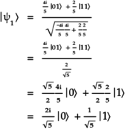
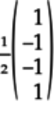
Since the probability of each collapsed state is
 , the magnitude of each
amplitude is the square root of .
Thus, the quantum state for the mega-qubit is:
, the magnitude of each
amplitude is the square root of .
Thus, the quantum state for the mega-qubit is:

-
To write the quantum state as a tensor product, factor the previous equation as follows:

-
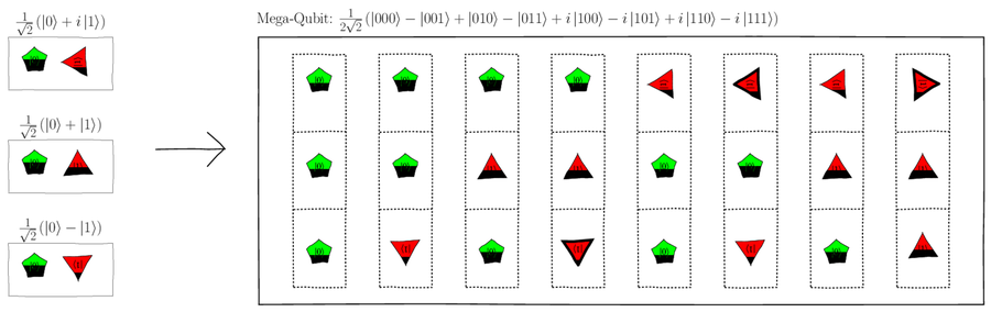
The tensor product obtained in the previous part can be drawn as shown in the following figure:
The top qubit on the left,
,
can be obtained by splitting
using an H gate.
The bottom qubit on the left,
,
has a 90°-rotated triangle
qubelet. Hence, after splitting
with an H gate, use an S gate
to give the triangle qubelet
a quarter turn anticlockwise.
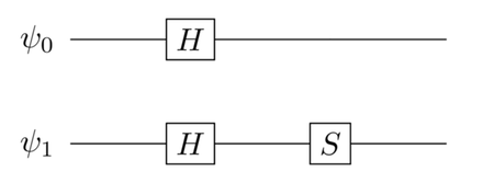
The quantum circuit to create this mega-qubit is shown in the following figure:
-
-
No. Once you teleport
,
the  and
and  qubits collapse and are no longer entangled. Furthermore,
they are physically distant from each other. Thus,
this circuit can no longer teleport any more quantum
states—teleporting circuits are single-use
circuits. Once they’re done teleporting, the qubits are
no longer useful. If you want to teleport another state,
you need another pair of and
qubits.
qubits collapse and are no longer entangled. Furthermore,
they are physically distant from each other. Thus,
this circuit can no longer teleport any more quantum
states—teleporting circuits are single-use
circuits. Once they’re done teleporting, the qubits are
no longer useful. If you want to teleport another state,
you need another pair of and
qubits.
-
When the
and
qubits collapse, the
qubit is:
The
qubit will have
one pentagon qubelet and
a triangle qubelet that is
rotated a quarter turn clockwise.
Since
 ,
you’ll need to apply a Z gate to the
qubit to obtain the
state that will be teleported.
,
you’ll need to apply a Z gate to the
qubit to obtain the
state that will be teleported.
The Z gate doesn’t affect the pentagon
gate but
turns the triangle qubelet
180° so that it ends up rotated a quarter
turn anticlockwise. Thus, the state that is
teleported is:

-
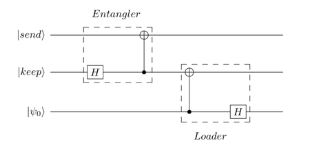
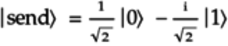
Yes, the circuit can be used to teleport a quantum state.
The Entangler and Loader blocks, together with the
,
, and the
quantum state to be teleported,
, are labeled as shown in
the following circuit: