
In this chapter, we will cover the following topics:
- Controlling an LED
- Responding to a button
- A controlled shutdown button
- The GPIO keypad input
- Multiplexed color LEDs
- Writing messages using Persistence of Vision
One of the key features of a Raspberry Pi computer that sets it apart from most other home/office computers is that it has the ability to directly interface with other hardware. The hardware General Purpose Input/Output (GPIO) pins on the Raspberry Pi can control a wide range of low-level electronics, from Light Emitting Diodes (LEDs) to switches, sensors, motors, servos, and even extra displays.
This chapter will focus on connecting the Raspberry Pi with some simple circuits and getting to grips with using Python to control and respond to the connected components.
The Raspberry Pi hardware interface consists of 40 pins located along one side of the board.
Note
The GPIO pins and their layout will vary slightly according to the particular model you have.
The Raspberry Pi 2 and the Raspberry Pi 1 Model A Plus and B Plus all have the same 40-pin layout.
The older Raspberry Pi 1 models (non-plus types) have a 26-pin header, which is the same as the 1-26 pins of the newer models.
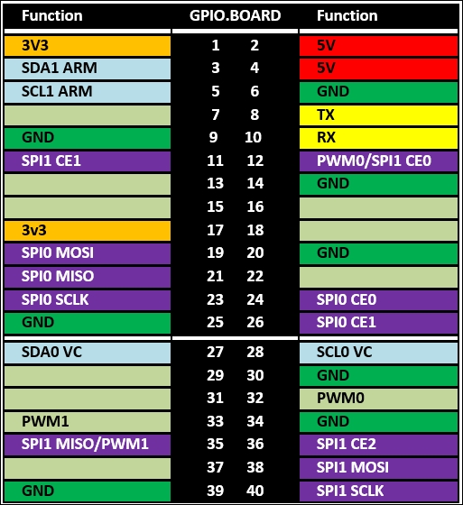
Raspberry Pi 2 and Raspberry Pi Model Plus GPIO header pins (pin functions)
The layout of the connector is shown in the previous diagram; the pin numbers are shown as seen from pin 1 of the GPIO header.
Pin 1 is at the end that is nearest to the SD card, as shown in the following image:
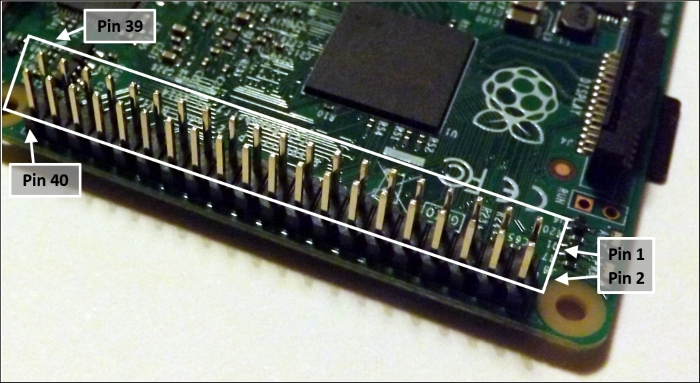
The Raspberry Pi GPIO header location
Care should be taken when using the GPIO header, since it also includes power pins (3V3 and 5V) as well as ground pins (GND). All of the GPIO pins can be used as standard GPIO, but several also have special functions; these are labeled and highlighted with different colors.
Tip
It is common for engineers to use a 3V3 notation to specify values in schematics to avoid using decimal places that could easily be missed (using 33V rather than 3.3V would cause severe damage). The same can applied to other values such as resistors, so for example, 1.2k ohms can be written as 1k2 ohms.
There are TX and RX pins that are used for serial RS232 communications, and with the aid of a voltage level convertor, information can be transferred via a serial cable to another computer or device.
We have SDA and SCL pins that are able to support a two-wire bus communication protocol called I2C (on Model Plus and Raspberry Pi 2 boards there are two I2C channels: channel 1 ARM is for general use while channel 0 VC is typically used for identifying Hardware Attached on Top (HAT) modules). There are also the SPI MOSI, SPI MISO, SPI SCLK, SPI CE0, and SPI CE1 pins, which support another type of bus protocol called SPI for high-speed data. Finally, we have PWM0/1, which allows a pulse width modulation signal to be generated, which is useful for servos and generating analog signals.
However, we will focus on using just the standard GPIO functions in this chapter. The GPIO pin layout is shown in the following diagram:
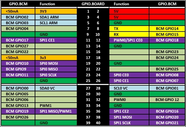
Raspberry Pi GPIO header pins (GPIO.BOARD and GPIO.BCM)
Tip
The Raspberry Pi Rev 2 (pre-July 2014) has the following differences to the Raspberry Pi 2 GPIO layout:
- 26 GPIO pins header (matching the first 26 pins)
- An additional secondary set of eight holes (P5) located next to the pin header. The details are as follows:
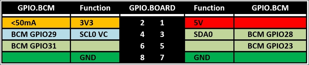
Raspberry Pi Rev 2 P5 GPIO header pins
The original Raspberry Pi Rev 1 (pre-Oct 2012) has only 26 GPIO pins in total (matching the first 26 pins of the current Raspberry Pi, except for the following details):
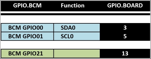
Raspberry Pi Rev 1 GPIO header differencesThe RPi.GPIO library can reference the pins on the Raspberry Pi using one of two systems. The numbers shown in the center are the physical position of the pins and are also the numbers referenced by RPi.GPIO when in the GPIO.BOARD mode. The numbers on the outside (GPIO.BCM) are the actual references for the physical ports of the processor to which the pins are wired (which is why they are not in any specific order). They are used when the mode is set to GPIO.BCM and allow control of the GPIO header pins and also any peripherals connected to other GPIO lines. This includes the LED on the add-on camera on BCM GPIO 4 and the status LED on the board. However, this can also include the GPIO lines used for reading/writing to the SD card, which would cause serious errors if interfered with.
If you use other programming languages to access the GPIO pins, the numbering scheme may be different, so it will be helpful if you are aware of the BCM GPIO references, which refer to the physical GPIO port of the processor.
Tip
Be sure to check out the Appendix, Hardware and Software List, which lists all the items used in this chapter and the places you can obtain them from.