
The hardware equivalent of hello world is an LED flash, which is a great test to ensure that everything is working and that you have wired it correctly. To make it a little more interesting, I've suggested using an RGB LED (it has red, green, and blue LEDs combined into a single unit), but feel free to use separate LEDs if that is all you have available.
You will need the following equipment:
- 4 x DuPont female to male patch wires
- Mini breadboard (170 tie points) or a larger one
- RGB LED (common cathode)/3 standard LEDs (ideally red/green/blue)
- Breadboarding wire (solid core)
- 3 x 470 ohm resistors
Each of the previous components should only cost a few dollars and can be reused for other projects afterwards. The breadboard is a particularly useful item that allows you to try out your own circuits without needing to solder them.
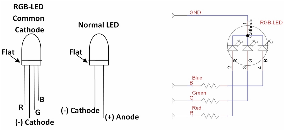
The diagrams of an RGB LED, standard LED, and RGB circuit
The following diagram shows the breadboard circuitry:
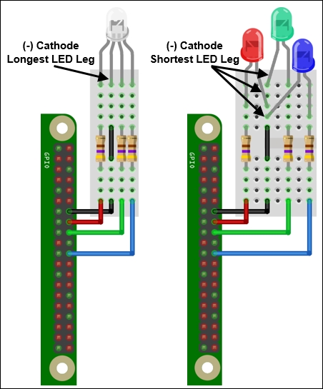
The wiring of an RGB LED/standard LEDs connected to the GPIO header
Note
There are several variations of RGB LEDs available, so check the datasheet of your component to confirm the pin order and type you have. Some are Red, Blue, and Green (RBG), so ensure that you wire accordingly or adjust the RGB_ pin settings in the code. You can also get common anode variants, which will require the anode to be connected to 3V3 (GPIO-Pin1) for it to light up (and require RGB_ENABLE and RGB_DISABLE to be set to 0 and 1).
The breadboard and component diagrams of this book have been created using a free tool called Fritzing (www.fritzing.org); it is great for planning your own Raspberry Pi projects.
Create the ledtest.py script as follows:
#!/usr/bin/python3
#ledtest.py
import time
import RPi.GPIO as GPIO
# RGB LED module
#HARDWARE SETUP
# GPIO
# 2[======XRG=B==]26[=======]40
# 1[=============]25[=======]39
# X=GND R=Red G=Green B=Blue
#Setup Active States
#Common Cathode RGB-LED (Cathode=Active Low)
RGB_ENABLE = 1; RGB_DISABLE = 0

#LED CONFIG - Set GPIO Ports
RGB_RED = 16; RGB_GREEN = 18; RGB_BLUE = 22
RGB = [RGB_RED,RGB_GREEN,RGB_BLUE]

def led_setup():
  #Setup the wiring
  GPIO.setmode(GPIO.BOARD)
  #Setup Ports
  for val in RGB:
    GPIO.setup(val,GPIO.OUT)

def main():
  led_setup()
  for val in RGB:
    GPIO.output(val,RGB_ENABLE)
    print("LED ON")
    time.sleep(5)
    GPIO.output(val,RGB_DISABLE)
    print("LED OFF")

try:
  main()
finally:
  GPIO.cleanup()
  print("Closed Everything. END")
#End
The RPi.GPIO library will require sudo permissions to access the GPIO pin hardware, so you will need to run the script using the following command:
sudo python3 ledtest.py
When you run the script, you should see the red, green, and blue parts of the LED (or each LED, if using separate ones) light up in turn. If not, double-check your wiring or confirm the LED is working by temporarily connecting the red, green, or blue wire to the 3V3 pin (pin 1 of the GPIO header).
Tip
The sudo command is required for most hardware-related scripts because it isn't normal for users to directly control hardware at such a low level. For example, setting or clearing a control pin that is part of the SD card controller could corrupt data being written to it. Therefore, for security purposes, super user permissions are required to stop programs from using hardware by accident (or with malicious intent).
To access the GPIO pins using Python, we import RPi.GPIO, which allows direct control of the pins through the module functions. We also require the time module to pause the program for a set number of seconds.
We define values for the LED wiring and active states (see Controlling the GPIO current in the There's more… section of this recipe).
Before the GPIO pins are used by the program, we need to set them up by specifying the numbering method (GPIO.BOARD) and the direction—GPIO.OUT or GPIO.IN (in this case, we set all the RGB pins to outputs). If a pin is configured as an output, we will be able to set the pin state; similarly, if it is configured as an input, we will be able to read the pin state.
Next, we control the pins using GPIO.ouput() by stating the number of the GPIO pin and the state we want it to be in (1 = high/on and 0 = low/off). We switch each LED on, wait 5 seconds, and then switch it back off.
Finally, we use GPIO.cleanup() to return the GPIO pins back to their original default state and release control of the pins for use by other programs.
Using the GPIO pins on the Raspberry Pi must be done with care since these pins are directly connected to the main processor of the Raspberry Pi without any additional protection. Caution must be used, as any incorrect wiring will probably damage the Raspberry Pi processor and cause it to stop functioning altogether.
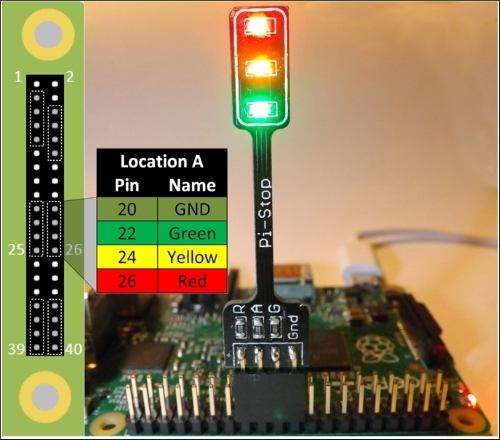
Alternatively, you could use one of the many modules available that plug directly into the GPIO header pins (reducing the chance of wiring mistakes).
Tip
For example, the Pi-Stop is a simple pre-built LED board that simulates a set of traffic lights, designed to be a stepping stone for those interested in controlling hardware but want to avoid the risk of damaging their Raspberry Pi. After the basics have been mastered, it also makes an excellent indicator to aid debugging.
Just ensure you update the LED CONFIG pin references in the ledtest.py script to reference the pin layout and location used for the hardware you are using.
See the Appendix, Hardware and Software List, for a list of Raspberry Pi hardware retailers.
Each GPIO pin is only able to handle a certain current before it will burn out (not greater than 16 mA from a single pin or 30 mA in total), and similarly, the RGB LED should be limited to no more than 100 mA. By adding a resistor before or after an LED, we will be able to limit the current that will be passed through it and also control how bright it is (more current will equal a brighter LED).
Since we may wish to drive more than one LED at a time, we typically aim to set the current as low as we can get away with while still providing enough power to light up the LED.
We can use Ohm's law to tell us how much resistance to use to provide a particular current. The law is as shown in the following diagram:
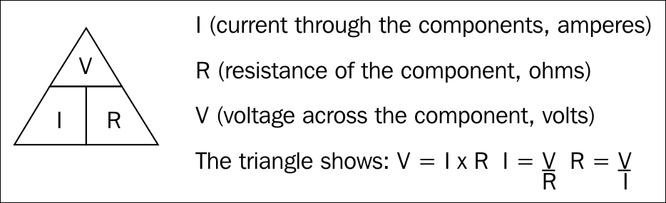
Ohm's law describes the relationship between the current, resistance, and voltage in electrical circuits
We will aim for a minimum current (3 mA) and maximum current (16 mA), while still producing a reasonably bright light from each of the LEDs. To get a balanced output for the RGB LEDs, I tested different resistors until they provided a near white light (when viewed through a card). A 470 ohm resistor was selected for each one (your LEDs may differ slightly).

Resistors are needed to limit the current that passes through the LEDs
The voltage across the resistor is equal to the GPIO voltage (Vgpio = 3.3V) minus the voltage drop on the particular LED (Vfwd); we can then use this resistance to calculate the current used by each of the LEDs, as shown in the following diagram:
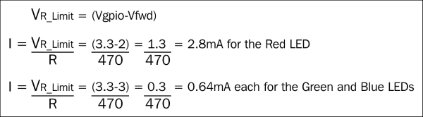
We can calculate the current drawn by each of the LEDs