
The Raspberry Pi should always be shut down correctly to avoid the SD card being corrupted (by losing power while performing a write operation to the card). This can pose a problem if you don't have a keyboard or screen connected (if you are running an automated program or controlling it remotely over a network and forget to turn it off) as you can't type the command or see what you are doing. By adding our own buttons and LED indicator, we can easily command a shutdown, reset, and startup again to indicate when the system is active.
You will need the following equipment:
- 3 x Dupont female to male patch wires
- Mini breadboard (170 tie points) or a larger one
- Push button switch (momentary close)
- General purpose LED
- 2 x 470-ohm resistors
- Breadboarding wire (solid core)
The entire layout of the shutdown circuit will look as shown in the following figure:
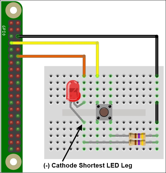
The controlled shutdown circuit layout
Create the shtdwn.py script as follows:
#!/usr/bin/python3
#shtdwn.py
import time
import RPi.GPIO as GPIO
import os

# Shutdown Script
DEBUG=True #Simulate Only
SNDON=True
#HARDWARE SETUP
# GPIO
# 2[==X==L=======]26[=======]40
# 1[===1=========]25[=======]39

#BTN CONFIG - Set GPIO Ports
GPIO_MODE=GPIO.BOARD
SHTDWN_BTN = 7 #1
LED = 12       #L

def gpio_setup():
  #Setup the wiring
  GPIO.setmode(GPIO_MODE)
  #Setup Ports
  GPIO.setup(SHTDWN_BTN,GPIO.IN,pull_up_down=GPIO.PUD_UP)
  GPIO.setup(LED,GPIO.OUT)

def doShutdown():
  if(DEBUG):print("Press detected")
  time.sleep(3)
  if GPIO.input(SHTDWN_BTN):
    if(DEBUG):print("Ignore the shutdown (<3sec)")
  else:
    if(DEBUG):print ("Would shutdown the RPi Now")
    GPIO.output(LED,0)
    time.sleep(0.5)
    GPIO.output(LED,1)
    if(SNDON):os.system("flite -t 'Warning commencing power down 3 2 1'")
    if(DEBUG==False):os.system("sudo shutdown -h now")
    if(DEBUG):GPIO.cleanup()
    if(DEBUG):exit()

def main():
  gpio_setup()
  GPIO.output(LED,1)
  while True:
    if(DEBUG):print("Waiting for >3sec button press")
    if GPIO.input(SHTDWN_BTN)==False:
       doShutdown()
    time.sleep(1)

try:
  main()
finally:
  GPIO.cleanup()
  print("Closed Everything. END")
#End
To get this script to run automatically (once we have tested it), we can place the script in ~/bin (we can use cp instead of mv if we just want to copy it) and add it to crontab with the following code:
mkdir ~/bin
mv shtdwn.py ~/bin/shtdwn.py
crontab –e
At the end of the file, we add the following code:
@reboot sudo python3 ~/bin/shtdwn.py
This time, when we set up the GPIO pin, we define the pin connected to the shutdown button as an input and the pin connected to the LED as an output. We turn the LED on to indicate that the system is running.
By setting the DEBUG flag to True, we can test the functionality of our script without causing an actual shutdown (by reading the terminal messages); we just need to ensure to set DEBUG to False when using the script for real.
We enter a while loop and check every second to see whether the GPIO pin is set to LOW (the switch has been pressed); if so, we enter the doShutdown() function.
The program will wait for 3 seconds and then test again to see whether the button is still being pressed. If the button is no longer being pressed, we return to the previous while loop. However, if it is still being pressed after 3 seconds, the program will flash the LED and trigger the shutdown (also providing an audio warning using flite).
When we are happy with how the script is operating, we can disable the DEBUG flag (by setting it to False) and add the script to crontab. Crontab is a special program that runs in the background and allows us to schedule (at specific times, dates, or periodically) programs and actions when the system is started (@reboot). This allows the script to be started automatically every time the Raspberry Pi is powered up. When we press and hold the shutdown button for more than 3 seconds, it safely shuts down the system and enters a low power state (the LED switches off just before this, indicating it is safe to remove the power shortly after). To restart the Raspberry Pi, we briefly remove the power; this will restart the system, and the LED will light up when the Raspberry Pi has loaded.
We can extend this example further using the reset header by adding extra functionality and making use of additional GPIO connections (if available).
The Raspberry Pi has holes for mounting a reset header (marked RUN on the Raspberry Pi 2 / 3 and P6 on the Raspberry Pi 1 Model B Rev 2 and Model As). The reset pin allows the device to be reset using a button rather than removing the micro USB connector each time to cycle the power:

Raspberry Pi reset headers – on the left, Raspberry Pi Model A/B (Rev2), and on the right, Raspberry Pi 2
To make use of it, you will need to solder a wire or pin header to the Raspberry Pi and connect a button to it (or briefly touch a wire between the two holes each time). Alternatively, we can extend our previous circuit, as shown in the following diagram:

The controlled shutdown circuit layout and reset button
We can add this extra button to our circuit, which can be connected to the reset header (this is the hole nearest the middle on the Raspberry Pi 2 or closest to the edge on other models). This pin, when temporarily pulled low by connecting to ground (such as the hole next to it or by another ground point such as pin 6 of the GPIO header), will reset the Raspberry Pi and allow it to boot up again following a shutdown.
Since we now have the script monitoring the shutdown button all the time, we can add extra buttons/switches/jumpers to be monitored at the same time. This will allow us to trigger specific programs or set up particular states just by changing the inputs. The following example allows us to easily switch between automatic DHCP networking (the default networking setup) and using a direct IP address, as used in the Networking directly to a laptop or computer recipe of Chapter 1, Getting Started with a Raspberry Pi Computer, for direct LAN connections.
Add the following components to the previous circuit:
- A 470-ohm resistor
- Two pin headers with a jumper connector (or optionally a switch)
- Breadboarding wire (solid core)
After adding the previous components, our controlled shutdown circuit now looks as follows:

The controlled shutdown circuit layout, reset button, and jumper pins
In the previous script, we add an additional input to detect the status of the LAN_SWA pin (the jumper pins we added to the circuit) using the following code:
LAN_SWA = 11 #2
Ensure that it is set up as an input (with a pull-up resistor) in the gpio_setup() function using the following code:
GPIO.setup(LAN_SWA,GPIO.IN,pull_up_down=GPIO.PUD_UP)
Add a new function to switch between the LAN modes, and read out the new IP address. The doChangeLAN() function checks if the status of the LAN_SWA pin has changed since the last call, and if so, it sets the network adaptor to DHCP or sets the direct LAN settings accordingly (and uses flite to speak the new IP setting if available). Finally, the LAN being set for direct connection causes the LED to flash slowly while that mode is active. Use the following code to do so:
def doChangeLAN(direct):
  if(DEBUG):print("Direct LAN: %s" % direct)
  if GPIO.input(LAN_SWA) and direct==True:
    if(DEBUG):print("LAN Switch OFF")
    cmd="sudo dhclient eth0"
    direct=False
    GPIO.output(LED,1)
  elif GPIO.input(LAN_SWA)==False and direct==False:
    if(DEBUG):print("LAN Switch ON")
    cmd="sudo ifconfig eth0 169.254.69.69"
    direct=True
  else:
    return direct
  if(DEBUG==False):os.system(cmd)
  if(SNDON):os.system("hostname -I | flite")
  return direct
Add another function, flashled(), which will just toggle the state of the LED each time it is called. The code for this function is as follows:
def flashled(ledon):
  if ledon:
    ledon=False
  else:
    ledon=True
  GPIO.output(LED,ledon)
  return ledon
Finally, we adjust the main loop to also call doChangeLAN() and use the result to decide whether we call flashled() using ledon to keep track of the LED's previous state each time. The main() function should now be updated as follows:
def main():
  gpio_setup()
  GPIO.output(LED,1)
  directlan=False
  ledon=True
  while True:
    if(DEBUG):print("Waiting for >3sec button press")
    if GPIO.input(SHTDWN_BTN)==False:
       doShutdown()
    directlan= doChangeLAN(directlan)
    if directlan:
      flashled(ledon)
    time.sleep(1)