
The Raspberry Pi can make an excellent tool for home automation by providing accurate timing, control, and the ability to respond to commands, button inputs, environmental sensors, or messages from the Internet.
Great care must be taken when controlling devices that use electricity from the mains since high voltages and currents are often involved.
Note
Never attempt to modify or alter devices that are connected to mains electricity without proper training. You must never directly connect any homemade devices to the mains supply. All electronics must undergo rigorous safety testing to ensure that there will be no risk or harm to people or property in the event of a failure.
In this example, we will use remote controlled radio frequency (RF) plug-in sockets; these use a separate remote unit to send a specific RF signal to switch any electrical device that is plugged into it on or off. This allows us to modify the remote control and use the Raspberry Pi to activate the switches safely, without interfering with dangerous voltages:

Remote control and remote mains socket
The particular remote control used in this example has six buttons on it to directly switch three different sockets on or off and is powered by a 12V battery. It can be switched into four different channels, which would allow you to control a total of 12 sockets (each socket has a similar selector that will be used to set the signal it will respond to).
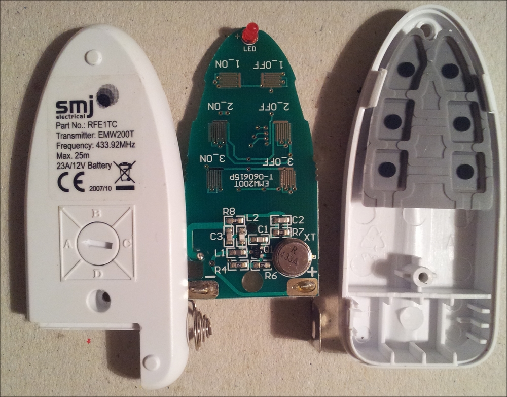
Inside the remote control
The remote buttons, when pressed, will broadcast a specific RF signal (this one uses a transmission frequency of 433.92 MHz). This will trigger any socket(s) that is set to the corresponding channel (A, B, C, or D) and number (1, 2, or 3).
Internally, each of the buttons connects two separate signals to ground, the number (1, 2, or 3), and state (on or off). This triggers the correct broadcast that is to be made by the remote control.
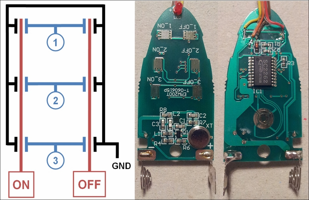
Connect the wires to ON, OFF, 1, 2, 3, and GND at suitable points on the remote's PCB (only ON, OFF, 1, and GND are connected in the image)
It is recommended that you do not connect anything to your sockets that could cause a hazard if switched on or off. The signals sent by the remote are not unique (there are only four different channels available). This therefore makes it possible for someone else nearby who has a similar set of sockets to unknowingly activate/deactivate one of your sockets. It is recommended that you select a channel other than the default, A, which will slightly reduce the chance of someone else accidentally using the same channel.
To allow the Raspberry Pi to simulate the button presses of the remote, we will need five relays to allow us to select the number (1, 2, or 3) and state (on or off).
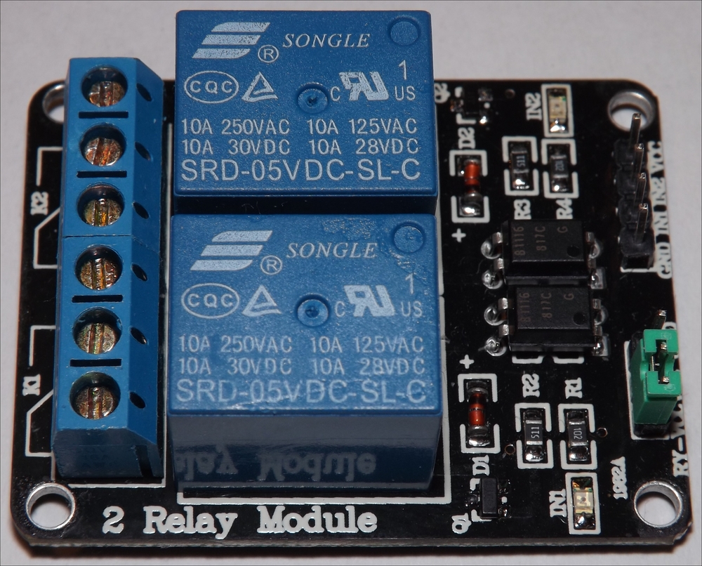
A prebuilt Relay Module can be used to switch the signals
Alternatively, the transistor and relay circuit from Chapter 9, Building Robots, can be used to simulate the button presses.
Wire the relay control pins to the Raspberry Pi GPIO and connect the socket remote control to each relay output as follows:

The socket remote control circuit
Create the following socketControl.py script:
#!/usr/bin/python3
# socketControl.py
import time
import RPi.GPIO as GPIO
#HARDWARE SETUP
# P1
# 2[V=G====XI====]26[=======]40
# 1[=====321=====]25[=======]39
#V=5V  G=Gnd
sw_num=[15,13,11]#Pins for Switch 1,2,3
sw_state=[16,18]#Pins for State X=Off,I=On
MSGOFF=0; MSGON=1
SW_ACTIVE=0; SW_INACTIVE=1

class Switch():
  def __init__(self):
    self.setup()
  def __enter__(self):
    return self
  def setup(self):
    print("Do init")
    #Setup the wiring
    GPIO.setmode(GPIO.BOARD)
    for pin in sw_num:
      GPIO.setup(pin,GPIO.OUT)
    for pin in sw_state:
      GPIO.setup(pin,GPIO.OUT)
    self.clear()
  def message(self,number,state):
    print ("SEND SW_CMD: %s %d" % (number,state))
    if state==MSGON:
      self.on(number)
    else:
      self.off(number)
  def on(self,number):
    print ("ON: %d"% number)
    GPIO.output(sw_num[number-1],SW_ACTIVE)
    GPIO.output(sw_state[MSGON],SW_ACTIVE)
    GPIO.output(sw_state[MSGOFF],SW_INACTIVE)
    time.sleep(0.5)
    self.clear()
  def off(self,number):
    print ("OFF: %d"% number)
    GPIO.output(sw_num[number-1],SW_ACTIVE)
    GPIO.output(sw_state[MSGON],SW_INACTIVE)
    GPIO.output(sw_state[MSGOFF],SW_ACTIVE)
    time.sleep(0.5)
    self.clear()
  def clear(self):
    for pin in sw_num:
      GPIO.output(pin,SW_INACTIVE)
    for pin in sw_state:
      GPIO.output(pin,SW_INACTIVE)
  def __exit__(self, type, value, traceback):
    self.clear()
    GPIO.cleanup()
def main():
  with Switch() as mySwitches:
    mySwitches.on(1)
    time.sleep(5)
    mySwitches.off(1)

if __name__ == "__main__":
    main()
#End
The socket control script performs a quick test by switching the first socket on for 5 seconds and then turning it off again.
To control the rest of the sockets, create a GUI menu as follows:
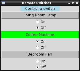
Remote Switches GUI
Create the following socketMenu.py script:
#!/usr/bin/python3
#socketMenu.py
import tkinter as TK
import socketControl as SC

#Define Switches ["Switch name","Switch number"]
switch1 = ["Living Room Lamp",1]
switch2 = ["Coffee Machine",2]
switch3 = ["Bedroom Fan",3]
sw_list = [switch1,switch2,switch3]
SW_NAME = 0; SW_CMD  = 1
SW_COLOR=["gray","green"]

class swButtons:
  def __init__(self,gui,sw_index,switchCtrl):
    #Add the buttons to window
    self.msgType=TK.IntVar()
    self.msgType.set(SC.MSGOFF)
    self.btn = TK.Button(gui,
                  text=sw_list[sw_index][SW_NAME],
                  width=30, command=self.sendMsg,
                  bg=SW_COLOR[self.msgType.get()])
    self.btn.pack()
    msgOn = TK.Radiobutton(gui,text="On",
              variable=self.msgType, value=SC.MSGON)
    msgOn.pack()
    msgOff = TK.Radiobutton(gui,text="Off",
              variable=self.msgType,value=SC.MSGOFF)
    msgOff.pack()
    self.sw_num=sw_list[sw_index][SW_CMD]
    self.sw_ctrl=switchCtrl
  def sendMsg(self):
    print ("SW_CMD: %s %d" % (self.sw_num,
                              self.msgType.get()))
    self.btn.configure(bg=SW_COLOR[self.msgType.get()])
    self.sw_ctrl.message(self.sw_num,
                         self.msgType.get())

root = TK.Tk()
root.title("Remote Switches")
prompt = "Control a switch"
label1 = TK.Label(root, text=prompt, width=len(prompt),
                  justify=TK.CENTER, bg='lightblue')
label1.pack()
#Create the switch
with SC.Switch() as mySwitches:
  #Create menu buttons from sw_list
  for index, app in enumerate(sw_list):
    swButtons(root,index,mySwitches)
  root.mainloop()
#EndThe first script defines a class called Switch; it sets up the GPIO pins required to control the five relays (within the setup function). It also defines the __enter__ and __exit__ functions, which are special functions used by the with..as statement. When a class is created using with..as, it uses __enter__ to perform any extra initialization or setup (if required), and then it performs any cleanup by calling __exit__. When the Switch class has been executed, all the relays are switched off to preserve the remote's battery and GPIO.cleanup() is called to release the GPIO pins. The parameters of the __exit__ function (type, value, and traceback) allow the handling of any specific exceptions that may have occurred when the class was being executed within the with..as statement (if required).
To control the sockets, create two functions that will switch the relevant relays on or off to activate the remote control to send the required signal to the sockets. Then, shortly after, turn the relays off again using clear(). To make controlling the switches even easier, create a message function that will allow a switch number and state to be specified.
We make use of the socketControl.py script by creating a Tkinter GUI menu. The menu is made up of three sets of controls (one for each of the switches) that are defined by the swButtons class.
The swButtons class creates a Tkinter button and two Radiobutton controls. Each swButtons object is given an index and a reference to the mySwitches object. This allows us to set a name for the button and control a particular switch when it is pressed. The socket is activated/deactivated by calling message(), with the required switch number and state set by the Radiobutton controls.
The previous example allows you to rewire the remotes of most remote controlled sockets, but another option is to emulate the signals to control it directly.
Instead of rewiring the remote control, you can replicate the remote's RF signals using a transmitter that uses the same frequency as your sockets (these particular units use 433.94 MHz). This will depend on the particular sockets and sometimes your location—some countries prohibit the use of certain frequencies—as you may require certification before making your own transmissions:

The 433.94 MHz RF transmitter (left) and receiver (right)
The signals sent by the RF remote control can be recreated using 433Utils created by http://ninjablocks.com. The 433Utils uses WiringPi and are written in C++, allowing high speed capture and replication of the RF signals.
Obtain the code using the following command:
cd ~
wget https://github.com/ninjablocks/433Utils/archive/master.zip
unzip master.zip
Next, we need to wire up our RF transmitter (so we can control the switches) and RF receiver (so we can determine the control codes) to the Raspberry Pi.
The transmitter (the smaller square module) has three pins, which are power (VCC), ground (GND), and data out (ATAD). The voltage supplied on the power pin will govern the transmission range (we will use 5V supply from the Raspberry Pi, but you could replace this with 12V, as long as you ensure you connect the ground pin to both your 12V supply and the Raspberry Pi).
Although the receiver has four pins, there is a power pin (VCC), ground pin (GND), and two data out pins (DATA), which are wired together, so we only need to connect three wires to the Raspberry Pi.
|
RF Tx |
RPi GPIO pin |
RF Rx |
RPi GPIO pin | |
|---|---|---|---|---|
|
VCC (5V) |
2 |
VCC (3V3) |
1 | |
|
Data out |
11 |
Data in |
13 | |
|
GND |
6 |
GND |
9 |
Before we use the programs within the RPi_Utils, we will make a few adjustments to ensure our RX and TX pins are set correctly.
Locate codesend.cpp in 433Utils-master/RPi_utils/ to make the required changes:
cd ~/433Utils-master/RPi_utils
nano codesend.cpp -c
Change int PIN = 0; (located at around line 24) to int PIN = 11; (RPi physical pin number).
Change wiringPi to use physical pin numbering (located around line 27) by replacing wiringPiSetup() with wiringPiSetupPhy(). Otherwise, the default is WiringPi GPIO numbers; for more details, see http://wiringpi.com/reference/setup/. Find the following line:
if (wiringPiSetup () == -1) return 1;
Change it to this:
if (wiringPiSetupPhys () == -1) return 1;
Save and exit nano using Ctrl + X, Y.
Make similar adjustments to RFSniffer.cpp:
nano RFSniffer.cpp -c
Find the following line (located at around line 25):
int PIN = 2;
int PIN = 13; //RPi physical pin number
Find the following line (located at around line 27:
if(wiringPiSetup() == -1) {Change it to this:
if(wiringPiSetupPhys() == -1) {Save and exit nano using Ctrl + X, Y.
Build the code using the following command:
make all
This should build without errors, as shown here:
g++    -c -o codesend.o codesend.cpp
g++   RCSwitch.o codesend.o -o codesend -lwiringPi
g++    -c -o RFSniffer.o RFSniffer.cpp
g++   RCSwitch.o RFSniffer.o -o RFSniffer -lwiringPi
Now that we have our RF modules connected to the Raspberry Pi and our code ready, we can capture the control signals from our remote. Run the following command and take note of the reported output:
sudo ./RFSniffer
Get the output by pressing Button 1 OFF with the remote set to channel A (note we may get a few that pick up random noise):
Received 1381716
Received 1381716
Received 1381716
Received 1381717
Received 1398103
We can now send out the signals using the sendcode command to switch the sockets OFF (1381716) and ON (1381719):
sendcode 1381716
sendcode 1381719
You could even set up the Raspberry Pi to use the receiver module to detect signals from the remote (on an unused channel) and act upon them to start processes, control other hardware, or perhaps trigger a software shutdown/reboot.
The range of the transmitter is very limited when it is powered by 5V and without an additional antenna. However, it is worth testing everything before you make any modifications.
Simple wire antenna can be made from 25 cm of single core wire, 17 mm side connected to the antenna solder point, then 16 turns (made using a thin screwdriver shaft or similar) and the remaining wire on top (approximately 53 mm). This is described in more detail at .
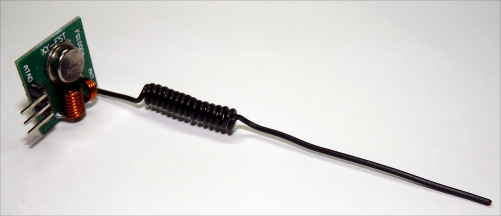
The transmitter range is vastly improved with a simple antenna
Recording the codes this for each of the buttons, we can determine the codes for each (and break down the structure):
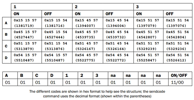
To select channel A, B, C, or D, set the two bits to 00. Similarly, for button 1, 2, or 3, set the two bits to 00 to select that button. Finally, set the last two bits to 11 for ON or 00 for OFF.
See https://arduinodiy.wordpress.com/2014/08/12/433-mhz-system-foryour-arduino/, which analyses these and other similar RF remote controls.
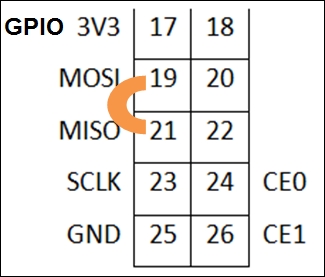
In Chapter 7, Sense and Display Real-World Data, we connected to devices using a bus protocol called I2C. The Raspberry Pi also supports another chip-to-chip protocol called SPI (Serial Peripheral Interface). The SPI bus differs from I2C because it uses two single direction data lines (where I2C uses one bidirectional data line). Although SPI requires more wires (I2C uses two bus signals, SDA and SCL), it supports the simultaneous sending and receiving of data and much higher clock speeds than I2C.
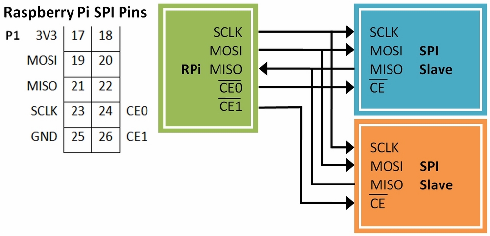
General connections of SPI devices with the Raspberry Pi
The SPI bus consists of the following four signals:
- SCLK: This provides the clock edges to read/write data on the input/output lines; it is driven by the master device. As the clock signal changes from one state to another, the SPI device will check the state of the MOSI signal to read a single bit. Similarly, if the SPI device is sending data, it will use the clock signal edges to synchronize when it sets the state of the MISO signal.
- CE: This refers to Chip Enable (typically, a separate Chip Enable is used for each slave device on the bus). The master device will set the Chip Enable signal to low for the device that it wants to communicate with. When the Chip Enable signal is set to high, it ignores any other signals on the bus. This signal is sometimes called Chip Select (CS) or Slave Select (SS).
- MOSI: This stands for Master Output, Slave Input (it connects to Data Out of the master device and Data In of the slave device).
- MISO: This stands for Master Input, Slave Output (it provides a response from the slave).
The following diagram shows each of the signals:
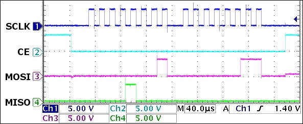
The SPI signals: SCLK (1), CE(2), MOSI(3), and MISO(4)
The previous scope trace shows two bytes being sent over SPI. Each byte is clocked into the SPI device using the SCLK (1) signal. A byte is signified by a burst of eight clock cycles (a low and then high period on the SCLK (1) signal), where the value of a specific bit is read when the clock state changes. The exact sample point is determined by the clock mode; in the following diagram, it is when the clock goes from low to high:
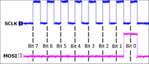
The first data byte sent by the Raspberry Pi to the SPI device on the MOSI(3) signal
The first byte sent is 0x01 (all the bits are low, except Bit 0) and the second sent is 0x03 (only Bit 1 and Bit 0 are high). At the same time, the MOSI (4) signal returns data from the SPI device—in this case, 0x08 (Bit 3 is high) and 0x00 (all the bits are low). The SCLK (1) signal is used to sync everything, even the data being sent from the SPI device.
The CE (2) signal is held low while the data is being sent to instruct that particular SPI device to listen to the MOSI (4) signal. When the CE (2) signal is set to high again, it indicates to the SPI device that the transfer has been completed.
The following is an image of an 8 x 8 LED matrix that is controlled via the SPI Bus:
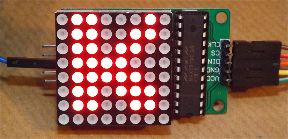
An 8 x 8 LED module displaying the letter K
The wiringPi library that we used previously for I2C also supports SPI. Ensure that wiringPi is installed (see Chapter 7, Sense and Display Real-World Data, for details) so that we can use it here.
Next, we need to enable SPI if we didn't do so when we enabled I2C previously:
sudo nano /boot/config.txt
Remove the # before #dtparam=spi=on to enable it, so it reads, and save (Ctrl + X, Y, Enter):
dtparam=spi=on
You can confirm that the SPI is active by listing all the running modules using the following command and locating spi_bcm2835:
lsmod
You can test the SPI with the following spiTest.py script:
#!/usr/bin/python3
# spiTest.py
import wiringpi

print("Add SPI Loopback - connect GPIO Pin19 and Pin21")
print("[Press Enter to continue]")
input()
wiringpi.wiringPiSPISetup(1,500000)
buffer=str.encode("HELLO")
print("Buffer sent %s" % buffer)
wiringpi.wiringPiSPIDataRW(1,buffer)
print("Buffer received %s" % buffer)
print("Remove the SPI Loopback")
print("[Press Enter to continue]")
input()
buffer=str.encode("HELLO")
print("Buffer sent %s" % buffer)
wiringpi.wiringPiSPIDataRW(1,buffer)
print("Buffer received %s" % buffer)
#End
Connect inputs 19 and 21 to create an SPI loopback for testing.
The SPI loopback test
You should get the following result:
Buffer sent b'HELLO'
Buffer received b'HELLO'
Remove the SPI Loopback
[Press Enter to continue]
Buffer sent b'HELLO'
Buffer received b'x00x00x00x00x00'
The example that follows uses an LED 8 x 8 matrix display that is being driven by an SPI-controlled MAX7219 LED driver:

An LED Controller MAX7219 pin-out, LED matrix pin-out, and LED matrix internal wiring (left to right)
Although the device has been designed to control eight separate 7-segment LED digits, we can use it for our LED matrix display. When used for digits, each of the seven segments (plus a decimal place) is wired to one of the SEG pins, and the COM connection of each of the digits is wired to the DIG pins. The controller then switches each of the segments on as required, while setting the relevant digit COM low to enable it. The controller can quickly cycle through each of the digits using the DIG pin fast enough that all eight appear to be lit at the same time:

A 7-segment LED digit uses segments A to G, plus DP (decimal place)
We use the controller in a similar way, except each SEG pin will connect to a column in the matrix and the DIG pins will enable/disable a row.
We use an 8 x 8 module connected to the MAX7219 chip as follows:
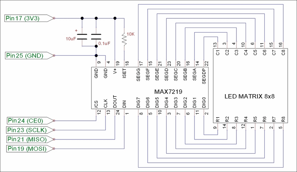
The MAX7219 LED controller driving an 8 x 8 LED matrix display
To control an LED matrix connected to an SPI MAX7219 chip, create the following matrixControl.py script:
#!/usr/bin/python3
# matrixControl.py
import wiringpi
import time

MAX7219_NOOP        = 0x00
DIG0=0x01; DIG1=0x02; DIG2=0x03; DIG3=0x04
DIG4=0x05; DIG5=0x06; DIG6=0x07; DIG7=0x08
MAX7219_DIGIT=[DIG0,DIG1,DIG2,DIG3,DIG4,DIG5,DIG6,DIG7]
MAX7219_DECODEMODE  = 0x09
MAX7219_INTENSITY   = 0x0A
MAX7219_SCANLIMIT   = 0x0B
MAX7219_SHUTDOWN    = 0x0C
MAX7219_DISPLAYTEST = 0x0F
SPI_CS=1
SPI_SPEED=100000

class matrix():
  def __init__(self,DEBUG=False):
    self.DEBUG=DEBUG
    wiringpi.wiringPiSPISetup(SPI_CS,SPI_SPEED)
    self.sendCmd(MAX7219_SCANLIMIT, 8)   # enable outputs
    self.sendCmd(MAX7219_DECODEMODE, 0)  # no digit decode
    self.sendCmd(MAX7219_DISPLAYTEST, 0) # display test off
    self.clear()
    self.brightness(7)                   # brightness 0-15
    self.sendCmd(MAX7219_SHUTDOWN, 1)    # start display
  def sendCmd(self, register, data):
    buffer=(register<<8)+data
    buffer=buffer.to_bytes(2, byteorder='big')
    if self.DEBUG:print("Send byte: 0x%04x"%
                        int.from_bytes(buffer,'big'))
    wiringpi.wiringPiSPIDataRW(SPI_CS,buffer)
    if self.DEBUG:print("Response:  0x%04x"%
                        int.from_bytes(buffer,'big'))
    return buffer
  def clear(self):
    if self.DEBUG:print("Clear")
    for row in MAX7219_DIGIT:
      self.sendCmd(row + 1, 0)
  def brightness(self,intensity):
    self.sendCmd(MAX7219_INTENSITY, intensity % 16)

def letterK(matrix):
    print("K")
    K=(0x0066763e1e366646).to_bytes(8, byteorder='big')
    for idx,value in enumerate(K):
        matrix.sendCmd(idx+1,value)

def main():
    myMatrix=matrix(DEBUG=True)
    letterK(myMatrix)
    while(1):
      time.sleep(5)
      myMatrix.clear()
      time.sleep(5)
      letterK(myMatrix)

if __name__ == '__main__':
    main()
#End
Running the script (python3 matrixControl.py) displays the letter K.
We can use a GUI to control the output of the LED matrix using matrixMenu.py:
#!/usr/bin/python3
#matrixMenu.py
import tkinter as TK
import time
import matrixControl as MC

#Enable/Disable DEBUG
DEBUG = True
#Set display sizes
BUTTON_SIZE = 10
NUM_BUTTON = 8
NUM_LIGHTS=NUM_BUTTON*NUM_BUTTON
MAX_VALUE=0xFFFFFFFFFFFFFFFF
MARGIN = 2
WINDOW_H = MARGIN+((BUTTON_SIZE+MARGIN)*NUM_BUTTON)
WINDOW_W = WINDOW_H
TEXT_WIDTH=int(2+((NUM_BUTTON*NUM_BUTTON)/4))
LIGHTOFFON=["red4","red"]
OFF = 0; ON = 1
colBg = "black"

def isBitSet(value,bit):
  return (value>>bit & 1)

def setBit(value,bit,state=1):
  mask=1<<bit
  if state==1:
    value|=mask
  else:
    value&=~mask
  return value

def toggleBit(value,bit):
  state=isBitSet(value,bit)
  value=setBit(value,bit,not state)
  return value

class matrixGUI(TK.Frame):
  def __init__(self,parent,matrix):
    self.parent = parent
    self.matrix=matrix
    #Light Status
    self.lightStatus=0
    #Add a canvas area ready for drawing on
    self.canvas = TK.Canvas(parent, width=WINDOW_W,
                        height=WINDOW_H, background=colBg)
    self.canvas.pack()
    #Add some "lights" to the canvas
    self.light = []
    for iy in range(NUM_BUTTON):
      for ix in range(NUM_BUTTON):
        x = MARGIN+MARGIN+((MARGIN+BUTTON_SIZE)*ix)
        y = MARGIN+MARGIN+((MARGIN+BUTTON_SIZE)*iy)
        self.light.append(self.canvas.create_rectangle(x,y,
                              x+BUTTON_SIZE,y+BUTTON_SIZE,
                              fill=LIGHTOFFON[OFF]))
    #Add other items
    self.codeText=TK.StringVar()
    self.codeText.trace("w", self.changedCode)
    self.generateCode()
    code=TK.Entry(parent,textvariable=self.codeText,
                  justify=TK.CENTER,width=TEXT_WIDTH)
    code.pack()
    #Bind to canvas not tk (only respond to lights)
    self.canvas.bind('<Button-1>', self.mouseClick)

  def mouseClick(self,event):
    itemsClicked=self.canvas.find_overlapping(event.x,
                             event.y,event.x+1,event.y+1)
    for item in itemsClicked:
      self.toggleLight(item)

  def setLight(self,num):
    state=isBitSet(self.lightStatus,num)
    self.canvas.itemconfig(self.light[num],
                           fill=LIGHTOFFON[state])

  def toggleLight(self,num):
    if num != 0:
      self.lightStatus=toggleBit(self.lightStatus,num-1)
      self.setLight(num-1)
      self.generateCode()

  def generateCode(self):
    self.codeText.set("0x%016x"%self.lightStatus)

  def changedCode(self,*args):
    updated=False
    try:
      codeValue=int(self.codeText.get(),16)
      if(codeValue>MAX_VALUE):
        codeValue=codeValue>>4
      self.updateLight(codeValue)
      updated=True
    except:
      self.generateCode()
      updated=False
    return updated

  def updateLight(self,lightsetting):
    self.lightStatus=lightsetting
    for num in range(NUM_LIGHTS):
      self.setLight(num)
    self.generateCode()
    self.updateHardware()

  def updateHardware(self):
    sendBytes=self.lightStatus.to_bytes(NUM_BUTTON,
                                        byteorder='big')
    print(sendBytes)
    for idx,row in enumerate(MC.MAX7219_DIGIT):
      response = self.matrix.sendCmd(row,sendBytes[idx])
      print(response)

def main():
  global root
  root=TK.Tk()
  root.title("Matrix GUI")
  myMatrixHW=MC.matrix(DEBUG)
  myMatrixGUI=matrixGUI(root,myMatrixHW)
  TK.mainloop()

if __name__ == '__main__':
    main()
#End
The Matrix GUI allows us to switch each of the LEDs on/off by clicking on each of the squares (or by directly entering the hexadecimal value) to create the required pattern.
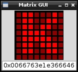
The Matrix GUI to control the 8 x 8 LED matrix
Initially, we defined addresses for each of the control registers used by the MAX7219 device. View the datasheet at for more information.
We created a class called matrix that will allow us to control the module. The __init__() function sets up the SPI of the Raspberry Pi (using SPI_CS as pin 26 CS1 and SPI_SPEED as 100 kHz).
The key function in our matrix class is the sendCmd() function; it uses wiringpi.wiringPiSPIDataRW(SPI_CS,buff) to send buffer (which is the raw byte data that we want to send) over the SPI bus (while also setting the SPI_CS pin low when the transfer occurs). Each command consists of two bytes: the first specifies the address of the register, and the second sets the data that needs to be put into it. To display a row of lights, we send the address of one of the ROW registers (MC.MAX7219_DIGIT) and the bit-pattern we want to display (as a byte).
Note
After the wiringpi.wiringPiSPIDataRW() function is called, buffer contains the result of whatever is received on the MISO pin (which is read simultaneously as the data is sent via the MOSI pin). If connected, this will be the output of the LED module (a delayed copy of the data that was sent). Refer to the following There's more… section regarding daisy-chained SPI configurations to learn how the chip output can be used.
To initialize the MAX7219, we need to ensure that it is configured in the correct mode. First, we set the Scan Limit field to 7 (which enables all the DIG0 - DIG7 outputs). Next, we disable the built-in digit decoding since we are using the raw output for the display (and don't want it to try to display digits). We also want to ensure that the MAX7219_DISPLAYTEST register is disabled (if enabled, it would turn on all the LEDs).
We ensure the display is cleared by calling our own clear() function, which sends 0 to each of the MAX7219_DIGIT registers to clear each of the rows. Finally, we use the MAX7219_INTENSITY register to set the brightness of the LEDs. The brightness is controlled using a PWM output to make the LEDs appear brighter or darker according to the brightness that is required.
Within the main() function, we perform a quick test to display the letter K on the grid by sending a set of 8 bytes (0x0066763e1e366646).

Each 8 x 8 pattern consists of 8 bits in 8 bytes (one bit for each column, making each byte a row in the display)
The matrixGUI class creates a canvas object that is populated with a grid of rectangle objects to represent the 8 x 8 grid of LEDs we want to control (these are kept in self.light). We also add a text entry box to display the resulting bytes that we will send to the LED matrix module. We then bind the <Button-1> mouse event to the canvas so that mouseClick is called whenever a mouse click occurs within the area of the canvas.
We attach a function called changedCode() to the codeText variable using trace, a special Python function, which allows us to monitor specific variables or functions. If we use the 'w' value with the trace function, the Python system will call the callback function whenever the value is written to.
When the mouseClick() function is called, we use the event.x and event.y coordinates to identify the object that is located there. If an item is detected, then the ID of the item is used (via toggleLight()) to toggle the corresponding bit in the self.lightStatus value, and the color of the light in the display changes accordingly (via setLight()). The codeText variable is also updated with the new hexadecimal representation of the lightStatus value.
The changeCode() function allows us to use the codeText variable and translate it into an integer. This allows us to check whether it is a valid value. Since it is possible to enter text here freely, we must validate it. If we are unable to convert it to an integer, the codeValue text is refreshed using the lightStatus value. Otherwise, we check if it is too large, in which case we perform a bit-shift by four to divide it by 16 until it is within a valid range. We update the lightStatus value, the GUI lights, the codeText variable, and also the hardware (by calling updateHardware()).
The updateHardware() function makes use of the myMatrixHW object that was created using the MC.matrix class. We send the bytes that we want to display to the matrix hardware one byte at a time (along with the corresponding MAX7219_DIGIT value to specify the row).
The SPI bus allows us to control multiple devices on the same bus by using the Chip Enable signal. Some devices, such as the MAX7219, also allow what is known as a daisy-chain SPI configuration.
You may have noticed that the matrix class also returns a byte when we send the data on the MOSI line. This is the data output from the MAX7219 controller on the DOUT connection. The MAX7219 controller actually passes all the DIN data through to DOUT, which is one set of instructions behind the DIN data. In this way, the MAX7219 can be daisy-chained (with each DOUT feeding into the next DIN). By keeping the CE signal low, multiple controllers can be loaded with data by being passed though one another. The data is ignored while CE is set to low, the outputs will only be changed when we set it high again. In this way, you can clock in all the data for each of the modules in the chain and then set CE to high to update them:

The daisy-chain SPI configuration
We need to do this for each row that we wish to update (or use MAX7219_NOOP if we want to keep the current row the same). This is known as a daisy-chain SPI configuration, supported by some SPI devices, where data is passed through each device on the SPI bus to the next one, which allows the use of three bus control signals for multiple devices.
Traditionally, serial protocols such as RS232 are a common way to connect devices such as printers and scanners as well as joysticks and mouse devices to computers. Now, despite being superseded by USB, many peripherals still make use of this protocol for internal communication between components, to transfer data, and to update firmware. For electronics hobbyists, RS232 is a very useful protocol for debugging and controlling other devices while avoiding the complexities of USB.
The two scripts in this example allow for the control of the GPIO pins to illustrate how we can remotely control the Raspberry Pi through the serial port. The serial port could be connected to a PC, another Raspberry Pi, or even an embedded microcontroller (such as Arduino, PIC, or similar).
The easiest way to connect to the Raspberry Pi via a serial protocol will depend on whether your computer has a built-in serial port or not. The serial connection, software, and test setup are described in the following three steps:
- Create an RS232 serial connection between your computer and the Raspberry Pi. For this, you need one of the following setups:
- If your computer has a built-in serial port available, you can use a Null-Modem cable with an RS232 to USB adaptor to connect to the Raspberry Pi:
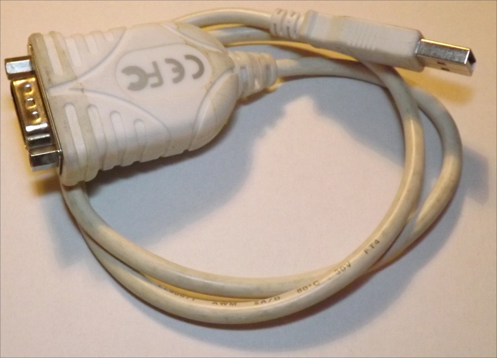
USB for an RS232 adaptor
A Null-Modem is a serial cable/adaptor that has the TX and RX wires crossed over so that one side is connected to the TX pin of the serial port, whereas the other side is connected to the RX pin:
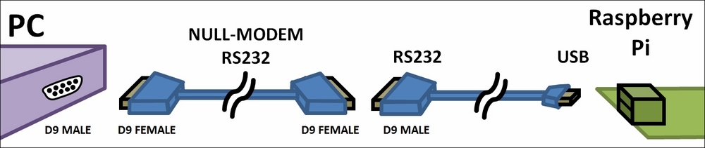
A PC serial port connected to the Raspberry Pi via a Null-Modem cable and an RS232 to USB adaptor
Note
A list of supported USB to RS232 devices is available at the following link: http://elinux.org/RPi_VerifiedPeripherals#USB_UART_and_USB_to_Serial_.28RS-232.29_adapters
Refer to the There's more… section for details on how to set them up.
If you do not have a serial port built into your computer, you can use another USB to RS232 adaptor to connect to the PC/laptop, converting the RS232 to the more common USB connection.
If you do not have any available USB ports on the Raspberry Pi, you can use the GPIO serial pins directly with either a Serial Console Cable or a Bluetooth serial module (refer to the There's more… section for details). Both of these will require some additional setup.
For all cases, you can use an RS232 loopback to confirm that everything is working and set up correctly (again, refer to the There's more… section).
- If your computer has a built-in serial port available, you can use a Null-Modem cable with an RS232 to USB adaptor to connect to the Raspberry Pi:
- Next, prepare the software you need for this example.
You will need to install pySerial so we can use the serial port with Python
- Install pySerial with the following command (you will also need PIP installed; refer to Chapter 3, Using Python for Automation and Productivity, for details):
sudo pip-3.2 install pyserial
Refer to the
pySerialsite for further documentation: https://pyserial.readthedocs.io/en/latest/.In order to demonstrate the RS232 serial control, you will require some example hardware attached to the Raspberry Pi's GPIO pins.
The
serialMenu.pyscript allows the GPIO pins to be controlled through commands sent through the serial port. To fully test this, you can connect suitable output devices (such as LEDs) to each of the GPIO pins. You can ensure that the total current is kept low using 470 ohm resistors for each of the LEDs so that the maximum GPIO current that the Raspberry Pi can supply is not exceeded: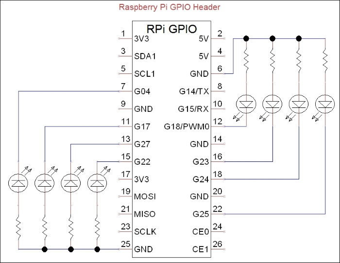
A test circuit to test the GPIO output via serial control
Create the following serialControl.py script:
#!/usr/bin/python3
#serialControl.py
import serial
import time

#Serial Port settings
SERNAME="/dev/ttyUSB0"
#default setting is 9600,8,N,1
IDLE=0; SEND=1; RECEIVE=1

def b2s(message):
  '''Byte to String'''
  return bytes.decode(message)
def s2b(message):
  '''String to Byte'''
  return bytearray(message,"ascii")

class serPort():
  def __init__(self,serName="/dev/ttyAMA0"):
    self.ser = serial.Serial(serName)
    print (self.ser.name)
    print (self.ser)
    self.state=IDLE
  def __enter__(self):
    return self
  def send(self,message):
    if self.state==IDLE and self.ser.isOpen():
      self.state=SEND
      self.ser.write(s2b(message))
      self.state=IDLE

  def receive(self, chars=1, timeout=5, echo=True,
              terminate="
"):
    message=""
    if self.state==IDLE and self.ser.isOpen():
      self.state=RECEIVE
      self.ser.timeout=timeout
      while self.state==RECEIVE:
        echovalue=""
        while self.ser.inWaiting() > 0:
          echovalue += b2s(self.ser.read(chars))
        if echo==True:
          self.ser.write(s2b(echovalue))
        message+=echovalue
        if terminate in message:
          self.state=IDLE
    return message
  def __exit__(self,type,value,traceback):
    self.ser.close()

def main():
  try:
    with serPort(serName=SERNAME) as mySerialPort:
      mySerialPort.send("Send some data to me!
")
      while True:
        print ("Waiting for input:")
        print (mySerialPort.receive())
  except OSError:
    print ("Check selected port is valid: %s" %serName)
  except KeyboardInterrupt:
    print ("Finished")

if __name__=="__main__":
  main()
#End
Ensure that the serName element is correct for the serial port we want to use (such as /dev/ttyAMA0 for the GPIO pins or /dev/ttyUSB0 for a USB RS232 adaptor).
Connect the other end to a serial port on your laptop or computer (the serial port can be another USB to RS232 adaptor).
Monitor the serial port on your computer using a serial program such as HyperTerminal or RealTerm () for Windows or Serial Tools for OS X. You will need to ensure that you have the correct COM port set and a baud rate of 9600 bps (Parity=None, Data Bits=8, Stop Bits=1, and Hardware Flow Control=None).
The script will send a request for data from the user and wait for a response.
To send data to the Raspberry Pi, write some text on the other computer and press Enter to send it over to the Raspberry Pi.
You will see output similar to the following on the Raspberry Pi terminal:
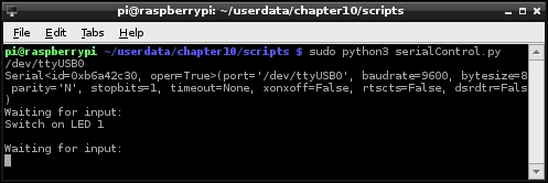
The text "Switch on LED 1" has been sent via a USB to RS232 cable from a connected computer
You will also see output similar to the following on the serial monitoring program:

RealTerm displaying typical output from the connected serial port
Press Ctrl + C on the Raspberry Pi to stop the script.
Now, create a GPIO control menu. Create serialMenu.py:
#!/usr/bin/python3
#serialMenu.py
import time
import RPi.GPIO as GPIO
import serialControl as SC
SERNAME = "/dev/ttyUSB0"
running=True
CMD=0;PIN=1;STATE=2;OFF=0;ON=1
GPIO_PINS=[7,11,12,13,15,16,18,22]
GPIO_STATE=["OFF","ON"]
EXIT="EXIT"
def gpioSetup():
GPIO.setmode(GPIO.BOARD)
for pin in GPIO_PINS:
GPIO.setup(pin,GPIO.OUT)
def handleCmd(cmd):
global running
commands=cmd.upper()
commands=commands.split()
valid=False
print ("Received: "+ str(commands))
if len(commands)==3:
if commands[CMD]=="GPIO":
for pin in GPIO_PINS:
if str(pin)==commands[PIN]:
print ("GPIO pin is valid")
if GPIO_STATE[OFF]==commands[STATE]:
print ("Switch GPIO %s %s"% (commands[PIN],
commands[STATE]))
GPIO.output(pin,OFF)
valid=True
elif GPIO_STATE[ON]==commands[STATE]:
print ("Switch GPIO %s %s"% (commands[PIN],
commands[STATE]))
GPIO.output(pin,ON)
valid=True
elif commands[CMD]==EXIT:
print("Exit")
valid=True
running=False
if valid==False:
print ("Received command is invalid")
response=" Invalid:GPIO Pin#(%s) %s
"% (
str(GPIO_PINS), str(GPIO_STATE))
else:
response=" OK
"
return (response)
def main():
try:
gpioSetup()
with SC.serPort(serName=SERNAME) as mySerialPort:
mySerialPort.send("
")
mySerialPort.send(" GPIO Serial Control
")
mySerialPort.send(" -------------------
")
mySerialPort.send(" CMD PIN STATE "+
"[GPIO Pin# ON]
")
while running==True:
print ("Waiting for command...")
mySerialPort.send(">>")
cmd = mySerialPort.receive(terminate="
")
response=handleCmd(cmd)
mySerialPort.send(response)
mySerialPort.send(" Finished!
")
except OSError:
print ("Check selected port is valid: %s" %serName)
except KeyboardInterrupt:
print ("Finished")
finally:
GPIO.cleanup()
main()
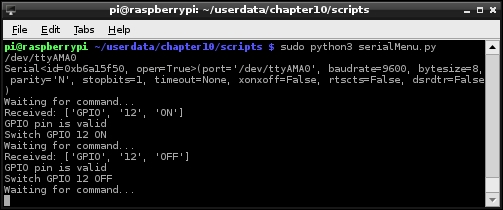
#EndWhen you run the script (sudo python3 serialMenu.py), type the control messages within the serial monitoring program:
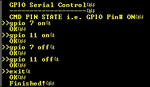
The GPIO Serial Control menu
The terminal output on the Raspberry Pi will be similar to the following screenshot, and the LEDs should respond accordingly:

The GPIO Serial Control menu
The Raspberry Pi validates the commands received from the serial connection and switches the LEDs connected to the GPIO pins 7 and 11 on and then off.
The first script, serialControl.py, provides us with a serPort class. We define the class with the following functions:
__init__(self,serName="/dev/ttyAMA0"): This function will create a new serial device usingserName—the default of"/dev/ttyAMA0" is the ID for the GPIO serial pins (see the There's more... section). After it is initialized, information about the device is displayed.__enter__(self): This is a dummy function that allows us to use thewith…asmethod.send(self,message): This is used to check that the serial port is open and not in use; if so, it will then send a message (after converting it to raw bytes using thes2b()function).receive(self, chars=1, echo=True, terminate=" "): After checking whether the serial port is open and not in use, this function then waits for data through the serial port. The function will collect data until the terminate characters are detected, and then the full message is returned.__exit__(self,type,value,traceback): This function is called when theserPortobject is no longer required by thewith…asmethod, so we can close the port at this point.
The main() function in the script performs a quick test of the class by sending a prompt for data through the serial port to a connected computer and then waiting for input that will be followed by the terminate character(s).
The next script, serialMenu.py, allows us to make use of the serPort class.
The main() function sets up the GPIO pins as outputs (via gpioSetup()), creates a new serPort object, and finally, waits for commands through the serial port. Whenever a new command is received, the handleCmd() function is used to parse the message to ensure that it is correct before acting on it.
The script will switch a particular GPIO pin on or off as commanded through the serial port using the GPIO command keyword. We could add any number of command keywords and control (or read) whatever device (or devices) we attached to the Raspberry Pi. We now have a very effective way to control the Raspberry Pi using any devices connected via a serial link.
In addition to the serial transmit and receive, the RS232 serial standard includes several other control signals. To test it, you can use a serial loopback to confirm if the serial ports are set up correctly.
Once you have connected the USB to RS232 device to the Raspberry Pi, check to see if a new serial device is listed by typing the following command:
dmesg | grep tty
The dmesg command lists events that occur on the system; using grep, we can filter any messages that mention tty, as shown in the following code:
[ 2409.195407] usb 1-1.2: pl2303 converter now attached to ttyUSB0
This shows that a PL2303-based USB-RS232 device was attached (2,409 seconds after startup) and allocated the ttyUSB0 identity. You will see that a new serial device has been added within the /dev/ directory (usually /dev/ttyUSB0 or something similar).
If the device has not been detected, you can try steps similar to the ones used in Chapter 1, Getting Started with a Raspberry Pi Computer, to locate and install suitable drivers (if they are available).
The RS232 serial standard has lots of variants and includes six additional control signals.
The Raspberry Pi GPIO serial drivers (and the Bluetooth TTL module used in the following example) only support RX and TX signals. If you require support for other signals, such as DTR that is often used for a reset prior to the programming of AVR/Arduino devices, then alternative GPIO serial drivers may be needed to set these signals via other GPIO pins. Most RS232 to USB adaptors should support the standard signals; however, ensure that anything you connect is able to handle standard RS232 voltages:

The RS232 9-Way D Connector pin-out and signals
For more details on the RS232 serial protocol and to know how these signals are used, visit the following link http://en.wikipedia.org/wiki/Serial_port:
Standard RS232 signals can range from -15V to +15V, so you must never directly connect any RS232 device to the GPIO serial pins. You must use an RS232 to TTL voltage-level converter (such as a MAX232 chip) or a device that uses TTL-level signals (such as another microcontroller or a TTL serial console cable):
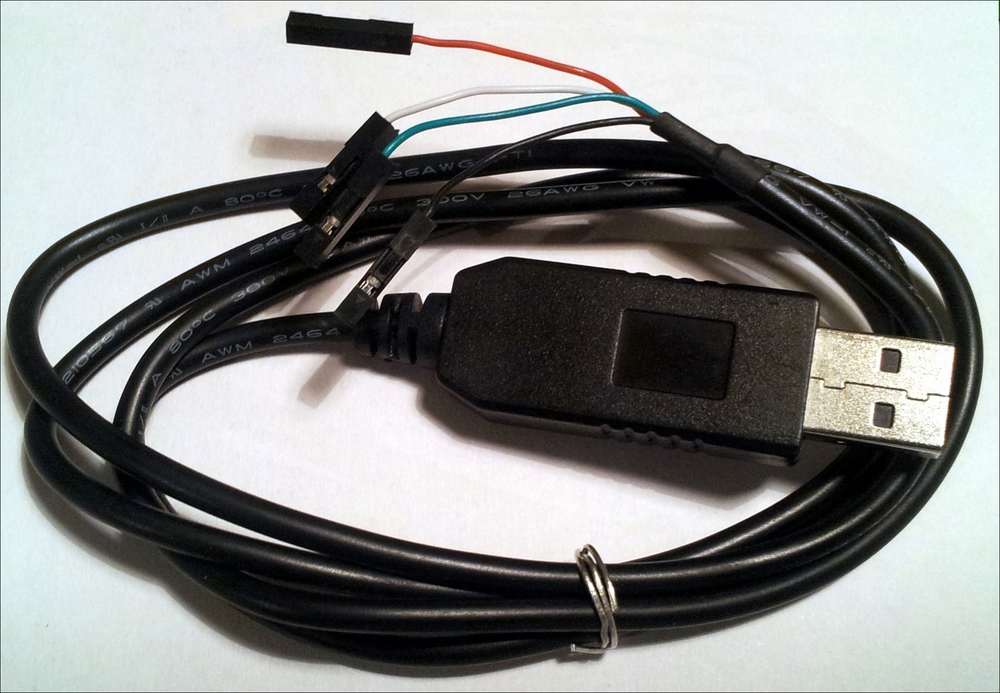
A USB to TTL serial console cable
The Raspberry Pi has TTL-level serial pins on the GPIO header that allow the connection of a TTL serial USB cable. The wires will connect to the Raspberry Pi GPIO pins, and the USB will plug in to your computer and be detected like a standard RS232 to USB cable.
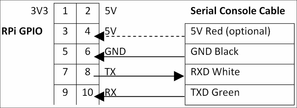
Connection of a USB to TTL serial console cable to the Raspberry Pi GPIO
It is possible to provide power from the USB port to the 5V pin; however, this will bypass the built-in polyfuse, so it is not recommended for general use (just leave the 5V wire disconnected and power as normal through the micro-USB).
By default, these pins are set up to allow remote terminal access, allowing you to connect to the COM port via PuTTY and create a serial SSH session.
Note
A serial SSH session can be helpful if you want to use the Raspberry Pi without a display attached to it.
However, a serial SSH session is limited to text-only terminal access since it does not support X10 Forwarding, as used in the Connecting remotely to Raspberry Pi over the network using SSH (and X11 Forwarding) section of Chapter 1, Getting Started with a Raspberry Pi Computer.
In order to use it as a standard serial connection, we have to disable the serial console so it is available for us to use.
First, we need to edit /boot/cmdline.txt to remove the first console and kgboc options (do not remove the other console=tty1 option, which is the default terminal when you switch on):
sudo nano /boot/cmdline.txt
dwc_otg.lpm_enable=0 console=ttyAMA0,115200 kgdboc=ttyAMA0,115200 console=tty1 root=/dev/mmcblk0p2 rootfstype=ext4 elevator=deadline rootwait
The previous command line becomes the following (ensure that this is still a single command line):
dwc_otg.lpm_enable=0 console=tty1 root=/dev/mmcblk0p2 rootfstype=ext4 elevator=deadline rootwait
We also have to remove the task that runs the getty command (the program that handles the text terminal for the serial connection) by commenting it out with #. This is set in /etc/inittab as follows:
sudo nano /etc/inittab
T0:23:respawn:/sbin/getty -L ttyAMA0 115200 vt100
The previous command line becomes the following:
#T0:23:respawn:/sbin/getty -L ttyAMA0 115200 vt100
To reference the GPIO serial port in our script, we use its name, /dev/ttyAMA0.
You can check whether the serial port connections are working correctly using a serial loopback.
A simple loopback consists of connecting RXD and TXD together. These are pins 8 and 10 on the Raspberry Pi GPIO header, or pins 2 and 3 on the standard RS232 D9 connector on the USB-RS232 adaptor:
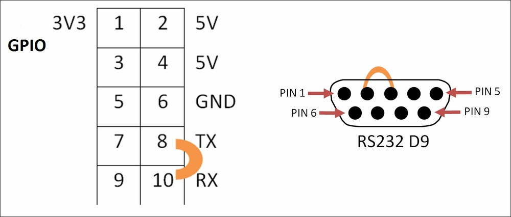
Serial loopback connections to test the Raspberry Pi GPIO (left) and RS232 9-Way D Connector (right)
An RS232 full loopback cable also connects pin 4 (DTR) and pin 6 (DSR) as well as pin 7 (RTS) and pin 8 (CTS) on the RS232 adaptor. However, this is not required for most situations, unless these signals are used. By default, no pins are allocated on the Raspberry Pi specifically for these additional signals.

RS232 full loopback
Create the following serialTest.py script:
#!/usr/bin/python3
#serialTest.py
import serial
import time

WAITTIME=1
serName="/dev/ttyAMA0"
ser = serial.Serial(serName)
print (ser.name)
print (ser)
if ser.isOpen():
  try:
    print("For Serial Loopback - connect GPIO Pin8 and Pin10")
    print("[Type Message and Press Enter to continue]")
    print("#:")
    command=input()
    ser.write(bytearray(command+"
","ascii"))
    time.sleep(WAITTIME)
    out=""
    while ser.inWaiting() > 0:
      out += bytes.decode(ser.read(1))
    if out != "":
      print (">>" + out)
    else:
      print ("No data Received")
  except KeyboardInterrupt:
    ser.close()
#End
When a loopback is connected, you will observe that the message is echoed back to the screen (when removed, No data Received will be displayed):

An RS232 loopback test on GPIO serial pins
If we require non-default settings, they can be defined when the serial port is initialized (the pySerial documentation at https://pyserial.readthedocs.io/en/latest/ provides full details of all the options), as shown in the following code:
ser = serial.Serial(port=serName, baudrate= 115200,
    timeout=1, parity=serial.PARITY_ODD,
    stopbits=serial.STOPBITS_TWO,
bytesize=serial.SEVENBITS)Serial data can also be sent through Bluetooth by connecting a HC-05 Bluetooth module that supports the Serial Port Profile (SPP) to the GPIO serial RX/TX pins. This allows the serial connection to become wireless, which allows Android tablets or smartphones to be used to control things and read data from the Raspberry Pi:
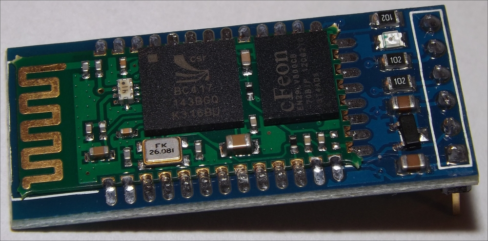
The HC-05 Bluetooth module for the TLL serial
Ensure that the serial console has been disabled (see the previous There's more… section).
The module should be connected using the following pins:

Connection to a Bluetooth module for the TLL serial
With the Bluetooth module configured and connected, we can pair the module with a laptop or smartphone to send and receive commands wirelessly. Bluetooth SPP Pro provides an easy way to use a serial connection over Bluetooth to control or monitor the Raspberry Pi for Android devices.
Alternatively, you may be able to set up a Bluetooth COM port on your PC/laptop and use it in the same way as the previous wired example:
- When the device is connected initially, the LED flashes quickly to indicate that it is waiting to be paired. Enable Bluetooth on your device and select the HC-05 device:
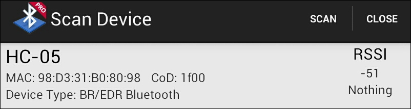
The HC-05 Bluetooth module viewable in Bluetooth SPP Pro
- Click on the Pair button to begin the pairing process and enter the device's PIN (the default is
1234):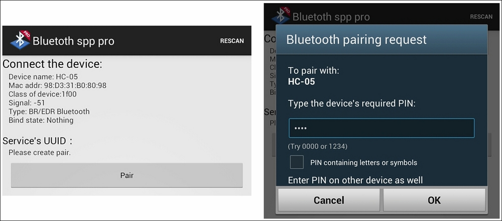
Pair the Bluetooth device with the PIN code (1234)
- If the pairing was successful, you will be able to connect with the device and send and receive messages to and from the Raspberry Pi:

Connect to the device and select the control method
- In Keyboard mode, you can define actions for each of the buttons to send suitable commands when pressed.
For example, Pin12 ON can be set to send
gpio 12 on, and Pin12 OFF can be set to sendgpio 12 off. - Ensure that you set the end flag to
- Ensure that
menuSerial.pyis set to use the GPIO serial connection:serName="/dev/ttyAMA0" - Run the
menuSerial.pyscript (with the LEDs attached):sudo python3 menuSerial.py - Check that the Bluetooth serial app displays the
GPIO Serial Controlmenu as shown in the following screenshot: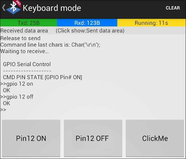
GPIO control over Bluetooth
We can see from the output in the following screenshot that the commands have been received and the LED connected to pin 12 has been switched on and off as required.
The Raspberry Pi receiving GPIO control over Bluetooth
By default, the Bluetooth module is set up to act like a TTL serial slave device, so we can simply plug it in to the GPIO RX and TX pins. Once the module is paired with a device, it will transfer the serial communication over the Bluetooth connection. This allows us to send commands and receive data via Bluetooth and control the Raspberry Pi using a smart phone or PC.
This means you can attach a second module to another device (such as an Arduino) that has TTL serial pins and control it using the Raspberry Pi (either by pairing it with another TTL Bluetooth module or suitably configuring a USB Bluetooth dongle). If the module is set up as a master device, then you will need to reconfigure it to act as a slave (see the There's more… section).
Now, let's understand how to configure the Bluetooth settings.
The Bluetooth module can be set in two different modes using the KEY pin.
In a normal operation, serial messages are sent over Bluetooth; however, if we need to change the settings of the Bluetooth module itself, we can do so by connecting the KEY pin to 3V3 and putting it into AT mode.
AT mode allows us to directly configure the module, allowing us to change the baud rate, the pairing code, the device name, or even set it up as a master/slave device.
You can use miniterm, which is part of pySerial, to send the required messages, as shown in the following code:
python3 -m serial.tools.miniterm
The miniterm program, when started, will prompt for the port to use:
Enter port name: /dev/ttyAMA0
You can send the following commands (you will need to do this quickly, or paste them, as the module will time out if there is a gap and respond with an error):
AT: This command should respond with OK.AT+UART?: This command will report the current settings asUART=<Param1>,<Param2>,<Param3>. The output of this command will be OK.- To change the current settings, use
AT+UART=<Param1>,<Param2>,<Param3>, that is,AT+UART=19200,0,0.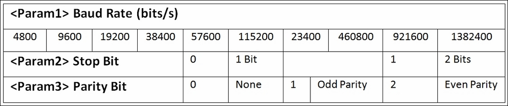
HC-05 AT mode AT+UART command parameters
For details on how to configure modules as paired master and slave devices (for example, between two Raspberry Pi devices), Zak Kemble has written an excellent guide. It is available at the following link: http://blog.zakkemble.co.uk/getting-bluetooth-modules-talking-to-each-other/.
For additional documentation on the HC-05 module, visit the following link: http://www.robotshop.com/media/files/pdf/rb-ite-12-bluetooth_hc05.pdf.
The Universal Serial Bus (USB) is used extensively by computers to provide additional peripherals and expansion through a common standard connection. We will use the PyUSB Python library to send custom commands to connected devices over USB.
The following example controls a USB toy missile launcher, which in turn allows it to be controlled by our Python control panel. We see that the same principle can be applied to other USB devices, such as a robotic arm, using similar techniques, and the controls can be activated using a sensor connected to the Raspberry Pi GPIO:

The USB Tenx Technology SAM missile launcher
We will need to install PyUSB for Python 3 using pip-3.2 as follows:
sudo pip-3.2 install pyusb
You can test whether PyUSB has installed correctly by running the following:
python3
> import usb
> help (usb)
> exit()
This should allow you to view the package information if it was installed correctly.
We will create the following missileControl.py script, which will include two classes and a default main() function to test it:
- Import the required modules as follows:
#!/usr/bin/python3
# missileControl.py
import time
import usb.core
- Define the
SamMissile()class, which provides the specific commands for the USB device, as follows:class SamMissile(): idVendor=0x1130 idProduct=0x0202 idName="Tenx Technology SAM Missile" # Protocol control bytes bmRequestType=0x21 bmRequest=0x09 wValue=0x02 wIndex=0x01 # Protocol command bytes INITA = [ord('U'), ord('S'), ord('B'), ord('C'), 0, 0, 4, 0] INITB = [ord('U'), ord('S'), ord('B'), ord('C'), 0, 64, 2, 0] CMDFILL = [ 8, 8, 0, 0, 0, 0, 0, 0, 0, 0, 0, 0, 0, 0, 0, 0, 0, 0, 0, 0, 0, 0, 0, 0, 0, 0, 0, 0, 0, 0, 0, 0, 0, 0, 0, 0, 0, 0, 0, 0, 0, 0, 0, 0, 0, 0, 0, 0, 0, 0, 0, 0, 0, 0, 0, 0, 0, 0]#48 zeros STOP = [ 0, 0, 0, 0, 0, 0] LEFT = [ 0, 1, 0, 0, 0, 0] RIGHT = [ 0, 0, 1, 0, 0, 0] UP = [ 0, 0, 0, 1, 0, 0] DOWN = [ 0, 0, 0, 0, 1, 0] LEFTUP = [ 0, 1, 0, 1, 0, 0] RIGHTUP = [ 0, 0, 1, 1, 0, 0] LEFTDOWN = [ 0, 1, 0, 0, 1, 0] RIGHTDOWN = [ 0, 0, 1, 0, 1, 0] FIRE = [ 0, 0, 0, 0, 0, 1] def __init__(self): self.dev = usb.core.find(idVendor=self.idVendor, idProduct=self.idProduct) def move(self,cmd,duration): print("Move:%s %d sec"% (cmd,duration)) self.dev.ctrl_transfer(self.bmRequestType, self.bmRequest,self.wValue, self.wIndex, self.INITA) self.dev.ctrl_transfer(self.bmRequestType, self.bmRequest,self.wValue, self.wIndex, self.INITB) self.dev.ctrl_transfer(self.bmRequestType, self.bmRequest, self.wValue, self.wIndex, cmd+self.CMDFILL) time.sleep(duration) self.dev.ctrl_transfer(self.bmRequestType, self.bmRequest, self.wValue, self.wIndex, self.INITA) self.dev.ctrl_transfer(self.bmRequestType, self.bmRequest, self.wValue, self.wIndex, self.INITB) self.dev.ctrl_transfer(self.bmRequestType, self.bmRequest, self.wValue, self.wIndex, self.STOP+self.CMDFILL) - Define the
Missile()class, which allows us to detect the USB device and provide command functions, as follows:class Missile(): def __init__(self): print("Initialize Missiles") self.usbDevice=SamMissile() if self.usbDevice.dev is not None: print("Device Initialized:" + " %s" % self.usbDevice.idName) #Detach the kernel driver if active if self.usbDevice.dev.is_kernel_driver_active(0): print("Detaching kernel driver 0") self.usbDevice.dev.detach_kernel_driver(0) if self.usbDevice.dev.is_kernel_driver_active(1): print("Detaching kernel driver 1") self.usbDevice.dev.detach_kernel_driver(1) self.usbDevice.dev.set_configuration() else: raise Exception("Missile device not found") def __enter__(self): return self def left(self,duration=1): self.usbDevice.move(self.usbDevice.LEFT,duration) def right(self,duration=1): self.usbDevice.move(self.usbDevice.RIGHT,duration) def up(self,duration=1): self.usbDevice.move(self.usbDevice.UP,duration) def down(self,duration=1): self.usbDevice.move(self.usbDevice.DOWN,duration) def fire(self,duration=1): self.usbDevice.move(self.usbDevice.FIRE,duration) def stop(self,duration=1): self.usbDevice.move(self.usbDevice.STOP,duration) def __exit__(self, type, value, traceback): print("Exit") - Finally, create a
main()function, which provides a quick test of ourmissileControl.pymodule if the file is run directly, as follows:def main(): try: with Missile() as myMissile: myMissile.down() myMissile.up() except Exception as detail: time.sleep(2) print("Error: %s" % detail) if __name__ == '__main__': main() #End
When the script is run using the following command, you should see the missile launcher move downwards and then up again:
sudo python3 missileControl.py
To provide easy control of the device, create the following GUI:
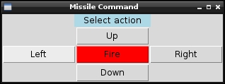
The Missile Command GUI
Although simple commands have been used here, you could use a series of preset commands if desired.
Create the GUI for the missileMenu.py missile command:
#!/usr/bin/python3
#missileMenu.py
import tkinter as TK
import missileControl as MC

BTN_SIZE=10

def menuInit():
  btnLeft = TK.Button(root, text="Left",
                      command=sendLeft, width=BTN_SIZE)
  btnRight = TK.Button(root, text="Right",
                       command=sendRight, width=BTN_SIZE)
  btnUp = TK.Button(root, text="Up",
                    command=sendUp, width=BTN_SIZE)
  btnDown = TK.Button(root, text="Down",
                      command=sendDown, width=BTN_SIZE)
  btnFire = TK.Button(root, text="Fire",command=sendFire,
                      width=BTN_SIZE, bg="red")
  btnLeft.grid(row=2,column=0)
  btnRight.grid(row=2,column=2)
  btnUp.grid(row=1,column=1)
  btnDown.grid(row=3,column=1)
  btnFire.grid(row=2,column=1)

def sendLeft():
  print("Left")
  myMissile.left()

def sendRight():
  print("Right")
  myMissile.right()

def sendUp():
  print("Up")
  myMissile.up()

def sendDown():
  print("Down")
  myMissile.down()

def sendFire():
  print("Fire")
  myMissile.fire()


root = TK.Tk()
root.title("Missile Command")
prompt = "Select action"
label1 = TK.Label(root, text=prompt, width=len(prompt),
                  justify=TK.CENTER, bg='lightblue')
label1.grid(row=0,column=0,columnspan=3)
menuInit()
with MC.Missile() as myMissile:
  root.mainloop()
#EndThe control script consists of two classes: one called Missile that provides a common interface for the control, and another called SamMissile that provides all the specific details of the particular USB device being used.
In order to drive a USB device, we need a lot of information about the device, such as its USB identification, its protocol, and the control messages it requires to be controlled.
The USB ID for the Tenx Technology SAM missile device is determined by the vendor ID (0x1130) and the product ID (0x0202). This is the same identification information you would see within Device Manager in Windows. These IDs are usually registered with www.usb.org; therefore, each device should be unique. Again, you can use the dmesg | grep usb command to discover these.
We use the device IDs to find the USB device using usb.core.find; then, we can send messages using ctrl_transfer().
The USB message has five parts:
- Request type (
0x21): This defines the type of the message request, such as the message direction (Host to Device), its type (Vendor), and the recipient (Interface) - Request (
0x09): This is the set configuration - Value (
0x02): This is the configuration value - Index (
0x01): This is the command we want to send - Data: This is the command we want to send (as described next)
The SamMissile device requires the following commands to move:
- It requires two initialization messages (
INITAandINITB). - It also requires the control message. This consists of the
CMD, which includes one of the control bytes that has been set to1for the required component. TheCMDis then added toCMDFILLto complete the message.
You will see that the other missile devices and the robot arm (see the following There's more… section) have similar message structures.
For each device, we created the __init__() and move() functions and defined values for each of the valid commands, which the missile class will use whenever the left(), right(), up(), down(), fire(), and stop() functions are called.
For the control GUI for our missile launcher, we create a small Tkinter window with five buttons, each of which will send a command to the missile device.
We import missileControl and create a missile object called myMissile that will be controlled by each of the buttons.
The example only shows how to control one particular USB device; however, it is possible to extend this to support several types of missile devices and even other USB devices in general.
There are several variants of USB missile-type devices, each with their own USB IDs and USB commands. We can add support for these other devices by defining their own classes to handle them.
Use lsusb -vv to determine the vendor and product ID that matches your device.
For Chesen Electronics/Dream Link, we have to add the following code:
class ChesenMissile():
  idVendor=0x0a81
  idProduct=0x0701
  idName="Chesen Electronics/Dream Link"
  # Protocol control bytes
  bmRequestType=0x21
  bmRequest=0x09
  wValue=0x0200
  wIndex=0x00
  # Protocol command bytes
  DOWN    = [0x01]
  UP      = [0x02]
  LEFT    = [0x04]
  RIGHT   = [0x08]
  FIRE    = [0x10]
  STOP    = [0x20]
  def __init__(self):
    self.dev = usb.core.find(idVendor=self.idVendor,
                             idProduct=self.idProduct)
  def move(self,cmd,duration):
    print("Move:%s"%cmd)
    self.dev.ctrl_transfer(self.bmRequestType,
                           self.bmRequest,
                           self.wValue, self.wIndex, cmd)
    time.sleep(duration)
    self.dev.ctrl_transfer(self.bmRequestType,
                           self.bmRequest, self.wValue,
                           self.wIndex, self.STOP)
For Dream Cheeky Thunder, we need the following code:
class ThunderMissile():
  idVendor=0x2123
  idProduct=0x1010
  idName="Dream Cheeky Thunder"
  # Protocol control bytes
  bmRequestType=0x21
  bmRequest=0x09
  wValue=0x00
  wIndex=0x00
  # Protocol command bytes
  CMDFILL = [0,0,0,0,0,0]
  DOWN    = [0x02,0x01]
  UP      = [0x02,0x02]
  LEFT    = [0x02,0x04]
  RIGHT   = [0x02,0x08]
  FIRE    = [0x02,0x10]
  STOP    = [0x02,0x20]
  def __init__(self):
    self.dev = usb.core.find(idVendor=self.idVendor,
                             idProduct=self.idProduct)
  def move(self,cmd,duration):
    print("Move:%s"%cmd)
    self.dev.ctrl_transfer(self.bmRequestType,
                           self.bmRequest, self.wValue,
                           self.wIndex, cmd+self.CMDFILL)
    time.sleep(duration)
    self.dev.ctrl_transfer(self.bmRequestType,
                      self.bmRequest, self.wValue,
                      self.wIndex, self.STOP+self.CMDFILL)
Finally, adjust the script to use the required class as follows:
class Missile():
  def __init__(self):
    print("Initialize Missiles")
self.usbDevice = ThunderMissile()Another device that can be controlled in a similar manner is the OWI Robotic Arm with a USB interface.

The OWI Robotic Arm with a USB interface (image courtesy of Chris Stagg)
This has featured in The MagPi magazine several times, thanks to Stephen Richards' articles on Skutter; the USB control has been explained in detail in issue 3 (page 14) at https://issuu.com/themagpi/docs/the_magpi_issue_3_final/14. It can also be found at https://www.raspberrypi.org/magpi/issues/3/.
The robotic arm can be controlled using the following class. Remember that you will also need to adjust the commands from UP, DOWN, and so on when calling the move() function, as shown in the following code:
class OwiArm():
  idVendor=0x1267
  idProduct=0x0000
  idName="Owi Robot Arm"
  # Protocol control bytes
  bmRequestType=0x40
  bmRequest=0x06
  wValue=0x0100
  wIndex=0x00
  # Protocol command bytes
  BASE_CCW    = [0x00,0x01,0x00]
  BASE_CW     = [0x00,0x02,0x00]
  SHOLDER_UP  = [0x40,0x00,0x00]
  SHOLDER_DWN = [0x80,0x00,0x00]
  ELBOW_UP    = [0x10,0x00,0x00]
  ELBOW_DWN   = [0x20,0x00,0x00]
  WRIST_UP    = [0x04,0x00,0x00]
  WRIST_DOWN  = [0x08,0x00,0x00]
  GRIP_OPEN   = [0x02,0x00,0x00]
  GRIP_CLOSE  = [0x01,0x00,0x00]
  LIGHT_ON    = [0x00,0x00,0x01]
  LIGHT_OFF   = [0x00,0x00,0x00]
  STOP        = [0x00,0x00,0x00]
The theory and method of control used for the USB missile device can be applied to very complex devices such as the Xbox 360's Kinect (a special 3D camera add-on for the Xbox game console) as well.
Adafruit's website has a very interesting tutorial written by Limor Fried (also known as Ladyada) on how to analyze and investigate USB commands; access it at http://learn.adafruit.com/hacking-the-kinect.
This is well worth a look if you intend to reverse engineer other USB items.