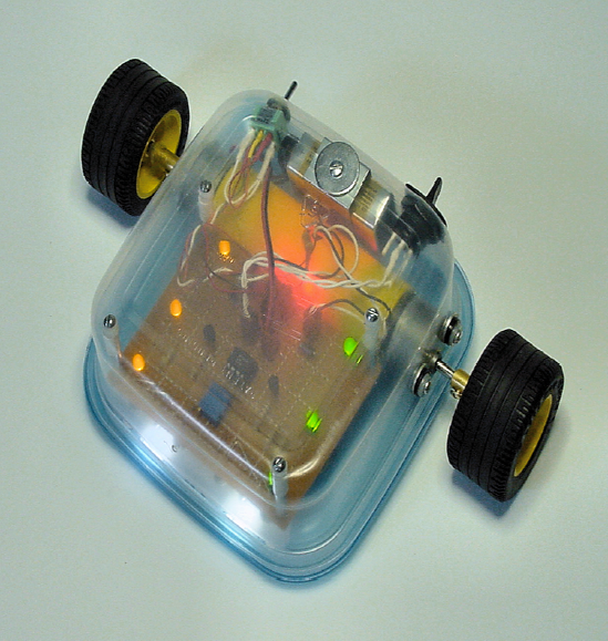
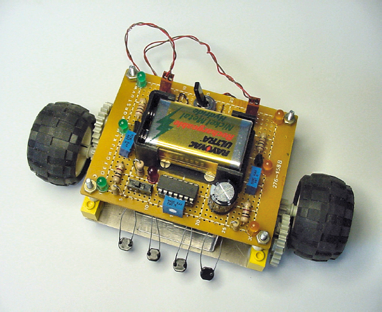
Sandwich, the robot featured in this book, is a robot that follows lines (see Figure 6-1). It's a rewarding project, because you can quickly lay out different courses, obstacles, and tunnels, and your robot immediately entertains you without any reprogramming.
A line-following robot usually contains the same building blocks that are universal to all robots. I have simplified Sandwich's line-following design to the point that only the most rudimentary forms of each module are necessary.
Even with a basic design, a decent robot still isn't particularly simple. There's a lot to learn and a lot to build. Only after understanding the individual components, circuits, and techniques will you be ready to combine them into a robot.
This chapter introduces the project goals. The following chapters walk you through component parts in detail. The line-following robot acts as a context for discussing many of the parts and circuits, but the part-specific information applies to all robots.
By making life easy on the robot, we'll make life easy on ourselves. Since this is a controlled scientific experiment, there's nothing wrong with reducing the environmental factors or variables that the robot is required to deal with.
The terrain must be flat and smooth, like a linoleum floor. Also acceptable is short, solid carpeting like commercial or non-patterned Berber loop-pile. Although softer flooring can reduce the robot's speed, the flooring is gentler on the robot's wheels and any parts that drag. On the other hand, sidewalk concrete quickly grinds down parts.
Do not permit obstacles, doors, or domesticated animals (including children) to interfere with the robot's path.
Indoor lighting conditions without heavy shadows are essential. Although you can make a robot to handle both indoor and outdoor driving, you would need additional electronics.
The width of the line to be followed should average from 1.8 cm to 2.54 cm (from ½ inch to an inch). The line must contrast well with the floor. Both the line and the floor should be solid colors, not patterns. In fact, solid white on solid black would make the robot happiest (see Figure 6-2). The line and floor must remain the same color throughout the course.
It doesn't matter what shade of floor you have because the robot is designed to follow either a darker line on a lighter floor or a lighter line on a darker floor.
How should you make your line? Painting the line can work very well. With paint, there is a wide variety of colors and glosses to choose from and you can control the line width. Some long-term upkeep may be necessary, but generally a painted line tends to be very durable. However, painting entails preparation time and is permanent.
Alternatively, wide-head marker pens work well on poster board. Make sure the lines are wide enough and cover the background thoroughly. Spotty, faded, or broken lines can cause the robot to drive off course.
For household courses, most people prefer tape lines. You can create, adjust, and remove non-permanent tape courses quickly. Tape rolls are easily obtained and come in the desired range of widths. Glossy (shiny) white cloth tape or flat (non-shiny) black cloth tape provides the highest contrast and thus is easiest for the robot to follow. Ordinary semi-translucent masking tape may not adequately cover the color and pattern of the floor underneath it.
Watch out for glossy dark materials. The shine reflects more light than you may realize, and it may not appear dark to the robot's sensors.
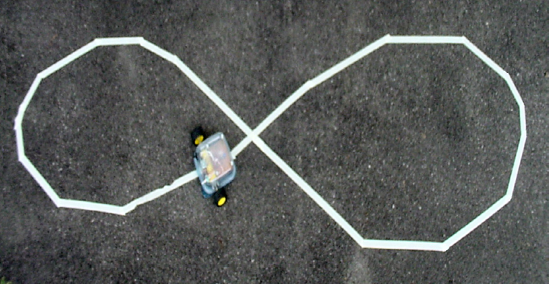
Tape lines can leave a sticky residue when removed. This is especially true in hot conditions or if the tape remains in place for too long. Blue masking tape (see Figure 6-3) or other low-adhesion varieties are much cleaner than ordinary off-white masking tape. For this reason, I use blue masking tape most often.
Warning: A mother contacted me regarding the difficulty of removing old tape from new hardwood flooring. She recommended the book include a warning. Now it does.
Avoid walking on tape, because it grinds it into the floor.
Test tape in a discreet location to ensure you can remove it without residue.
Don't allow tape to remain in place more than a week (or whatever the manufacturer recommends).
An interesting aspect of blue masking tape is that it isn't quite light and it isn't quite dark. The upside to this is that blue masking tape can be followed as a light line when placed on a dark background and a dark line when placed on a light background. The downside is that the maximum contrast is less than an actual white or black line.
There are two disadvantages to blue masking tape. First, the blue color reflects very little infrared, and therefore is not suitable for use as a light line for robots with infrared emitters. Second, unless firmly applied, blue tape can catch on the robot and get pulled up. Very-low-adhesion tape often suffers from this problem.
Straightaways are easy for any properly operating line follower. Sharp turns, however, can derail even a competent robot.
With reasonable brains and an array of sensors or a vision system, you could build a line-following robot to handle turns 45° or greater and also broken lines (see Figure 6-4). However, for the example robot, limit turn angles to 22.5° or less. Lines should always be contiguous.

Given a series of smaller turns over a longer distance, you can guide the robot in any direction (see Figure 6-5).

The better the surface contrast and the slower the robot's pace, the steeper the turns the robot can perform. Feel free to experiment with increasingly difficult arrangements. After all, the worst thing that can happen is that the robot wanders away.
Many designers fret over line crossings or line splits in the course (see Figure 6-6). It's possible for some robots to head between the lines as the brightness averages out. But, the robot circuit presented in this book isn't confused by such intersections, and quickly settles into one path choice or the other.

It's fun to watch the robot choose between equally split forks in the road. It doesn't always pick the same route. In fact, on multiline crossings, I've seen the robot take a wide turn and head off in the most remote direction. Perhaps it's just bored, but usually a shadow or bad hop explains the decision.
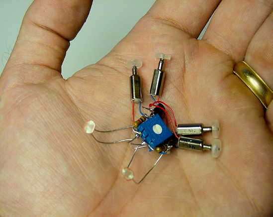
It would be cute to build a really tiny robot. Maybe one that fits into the palm of your hand (see Figure 6-7). Unfortunately, very small robots are difficult to assemble and work on. Small details require steady hands, patience, and experience. Like a miniature dollhouse, all of the parts on a small robot need to be equally small. This limits part choices and options.
At the other extreme, large robots are usually heavy, requiring larger motors to move. Large motors need a lot of power, which leads to a bigger battery. To support all the weight, the body must be constructed of stronger materials, which are harder to cut and drill.
Perhaps the best size for an amateur robot is around the size of a lunchbox. Plenty of parts fit those dimensions, standard consumer batteries provide enough power, and plastics and soft metals have enough strength for the forces exerted. Topping it all off, lunchbox-size robots fit well within the home.
This is not to say you'll forever be stuck crafting small creatures. With the successful completion of a few moderate designs, you can expand your work into the dimensions you desire. At that point, you'll already have experience with all of the robotic fundamentals, allowing you to concentrate on the unique obstacles that occur with other proportions.
There are many possible designs for a line-following robot. I'm presenting Sandwich's design because it contains the fewest and simplest parts possible, while still being cool and capable.
All of the components are currently being produced, so you don't have to use salvage. However, you can choose to make a couple of the pieces yourself from raw materials.
This robot is named Sandwich because its body is based on a sandwich container. Even if you choose a different shape, you can still apply the same circuit and techniques. Depending on the motors and containers you have lying around, your robot may turn out looking very different but with approximately the same line-following capabilities.
At first glance, Sandwich may appear to be a very complicated robot (see Figure 6-8). That's exactly the impression you want people to have. Blinking lights, colorful wires, production-quality wheels, metal screws, and a rounded case all add sophistication without adding much real work. Half of the battle is showmanship.
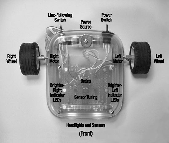
Don't be fooled or overwhelmed by it. This robot breaks down into smaller modules that are easily recreated. The next sections of this chapter describe the modules and switch functions.
At the rear of the robot is a toggle switch (see Figure 6-9). This switch has three positions: left, center, and right.
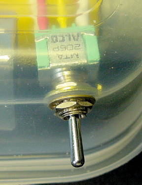
When the switch is in the left position, the left motor is connected to the left sensors and the right motor is connected to the right sensors. This allows the robot to follow dark-colored lines. When the switch is in the right position, the motor wires are crossed. The left motor is connected to the right sensors and the right motor is connected to the left sensors. This allows the robot to follow light-colored lines.
Believe it or not, switching the motor connections is all that it takes to follow different line brightnesses. No fancy algorithms or circuitry!
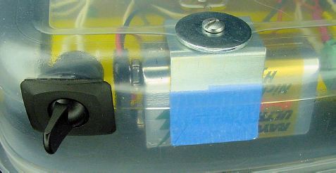
Also at the rear of the robot is a battery and a power switch (see Figure 6-10). The battery is an ordinary 9 V consumer battery.
Underneath the front of the robot are two headlights and four brightness sensors (see Figure 6-11). The headlights allow the robot to drive in darkness. By lighting the floor evenly, the headlights help prevent the robot from thinking a shadow is a dark line.
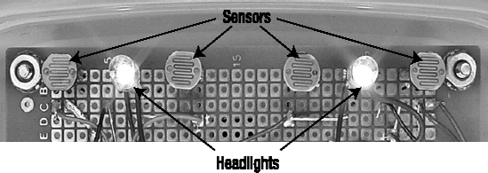
The four sensors are arranged in pairs: two sensors for the left side and two sensors for the right side. Technically, each side only requires a single sensor, but the leftmost and rightmost sensors act as safety nets in case the line sneaks by the middle sensors on a sharp turn.
When positioning the robot, the sensors should be centered over the line (see Figure 6-12). This way, the amount of light received is equally balanced between the left and right pairs of sensors.
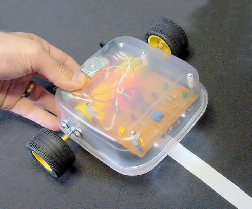
When the robot detects an imbalance of brightness, it knows it's off center. It then applies power to either the left or right motor to turn itself until the brightness is balanced again.
At the front of the robot is a small hole leading to a sensor adjustment dial (see Figure 6-13). A tiny screwdriver fits into the hole to turn the dial.
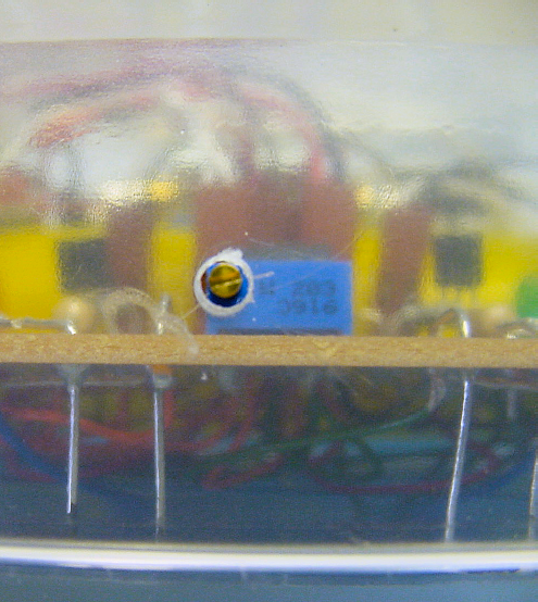
There are a number of reasons why a sensor adjustment dial is necessary. First, it would be very difficult to find four perfectly matched brightness sensors. Second, during soldering, one sensor is inevitably placed a little bit higher than another. Third, as the parts age or become soiled with dirt or dust, they may no longer provide the same sensitivity that they did originally.
With the adjustment dial, you can balance the left pair of sensors against the right pair. Since adjustments need to be made when the robot is already in place on a track, the dial must be accessible with the robot assembled. However, the dial needs to be recessed so it isn't nudged accidentally during handling. An internally mounted dial with an access hole ends up being the solution.
Fine-tuning dials are wise features to have.
If the robot isn't following a line or otherwise isn't responding correctly, it's important to have some indication of what the robot thinks it is seeing. Also, it would be impossible to properly adjust the sensor balance dial without some feedback from the robot as to which pair of sensors was seeing more light.
Three yellow LEDs light up on the right side when the right sensors see more brightness than the left sensors. Conversely, three green LEDs light up on the left side when the left sensors see more brightness (see Figure 6-14). When completely balanced, both sets of LEDs light up or blink off and on.
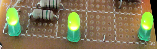
Two different colors were chosen so that you can tell which side is lit up even in the dark when the position of the body isn't visible. Three LEDs are used so that the indication is visible from any angle.
This robot isn't exactly the smartest cookie in the package. It simply turns on a motor and indicator light if one set of sensors is brighter, or turns on the other motor and indicator light if the other set of sensors is brighter.
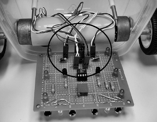
To accomplish this feat of genius, a chip called a comparator is used (see Figure 6-15). It compares two signals and flips a switch one way or another. That's it.
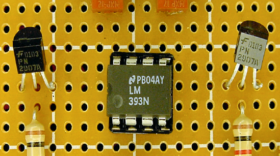
Unfortunately, a motor and three lights consume more power than the comparator chip can provide. So, transistors provide power to each side of the robot as the comparator directs.
The motors are fixed in a forward position without the ability to swivel for steering. Tiny steering columns are tricky to make at home and difficult to obtain in the sizes desired for a robot.
However, the robot can control its direction by varying the amount of power applied to each motor. Power to both motors drives the robot forward. Power only to the left motor causes the robot to turn right, pivoting around the right wheel. Power only to the right motor causes the robot to turn left, pivoting around the left wheel.
Sandwich has two wheels. If the robot had four wheels, it would be very difficult for it to pivot. Mainly the robot would go straight. On the occasions that it did turn, it would make a horrible vibrating noise as one pair of wheels was dragged horizontally rather than in the forward direction they want to roll.
There are other wheel arrangements possible, such as a single caster or ball roller on the front or rear, making a three-wheel robot. There are even omni-directional wheels available, containing multiple sets of perpendicular rollers. Although not a critical factor for small, lightweight robots, wheel formation becomes more significant with heavier or faster robots.
Mounting the two wheels toward the rear causes the front lip of the robot to drag on the ground. This isn't a big problem, although the plastic does scuff up a bit. Generally the plastic slides quite well in any direction. This makes for reasonably smooth forward movement and agile turning.
Sometimes the front of Sandwich skips and hops due to uneven or gritty terrain. With fresh batteries and tall wheels, Sandwich occasionally stands up on its rear and pops a wheelie! Even though that's a blast to watch, it causes the robot to momentarily lose sight of the line, sometimes causing it to head off course.
LEGO makes fantastic wheels. A wide variety of shapes, styles, and sizes are available from LEGO kits in retail stores, from online auctions, or from the LEGO Shop At Home web site. The prices are reasonable and no one produces higher-quality parts.
Most wheels consist of a tire (the outer rubbery part) and a rim with hub (the inner hard part). Almost all LEGO hubs are compatible with LEGO cross axles (see Figure 6-16).
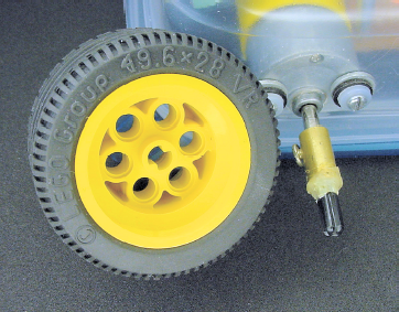
If there was a piece that could connect a motor to a standard LEGO cross axle, then your robot would have access to almost the entire line of LEGO wheels. It turns out that you can make such as part, called a coupler (see right side of Figure 6-16).
With a coupler, you can quickly slide different wheels on and off the robot, without needing tools. This is great for experimenting. It can also save you from a disaster if you suddenly discover the wheels you originally planned to use are too short or too wide.
I confess that Sandwich wasn't the first line-following robot I built for this book. The earlier model (see Figure 6-17) is good, but is more difficult to build. It has an aluminum base and bracket that have to be cut to size. Also, the sensors are exposed in front and bend every time the robot smacks into something. The electronics, wires, and gears are also exposed, which makes picking up the robot a delicate endeavor.
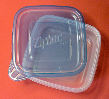
Using a consumer storage container solves all of those problems. For Sandwich, I chose a reusable/disposable square 2.5-cup plastic container from Ziploc (see Figure 6-18). Plastic containers are lightweight, inexpensive, easy to drill, and available at local grocery stores.
Most disposable food storage containers are made from polypropylene thermoplastic. Polypropylene is highly resistant to chemicals and moisture. It can resist boiling heat, although it will become brittle in freezing temperatures.
In Sandwich, no tape, rubber bands, or glue are used to connect the parts to the robot's body. Many hobbyists overuse these fastening methods, resulting in a sloppy or fragile robot. Additionally, it's awkward to disassemble pieces connected in that manner.
Whenever possible, use ordinary screws to connect parts to the body (see Figure 6-19). Screws have tremendous holding strength, they're durable, fairly inexpensive, look impressive, and you can remove and install them over and over. You can buy fasteners of all shapes and sizes at your local hardware store, or online at MSCDirect.com, MicroFasteners.com, or McMaster.com.
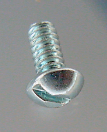
To whatever extent you can, use the same type and the same size screws throughout your robot. That way, you won't need to carry around a tool chest filled with a variety of screwdrivers to service your robot.
On Sandwich's main circuit board, all of the parts are connected with solder. This makes for a strong connection, though nearly permanent.
For electrical connections coming into the board, such as the power switch or motors, use a removable connector (see Figure 6-20). Not only is servicing a breeze, but you can pull parts for testing or even interchanging them with other robots.
Suppliers of individual parts are listed throughout this book, in the relevant chapters. However, you can save money and get a head start on the Sandwich robot by purchasing a kit (see Figure 6-21). Solarbotics sells part #K SAND for $49.95. This ensures that you have the correct components and reduces the time it would have taken to track down pieces from various vendors.
Of course, you still have the option of modifying the kit as desired, by substituting your own parts or decorations. In any case, you will need to supply a piece of plastic or container to hold the robot together.
You should now understand the line-following course requirements and the basic functional anatomy of Sandwich.
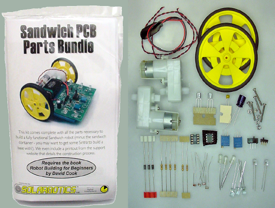
Figure 6.21. The Sandwich PCB Parts Bundle includes motors, wheels, printed circuit board, and electronics.
If you haven't soldered, drilled, or worked with electronics before, it may seem like a huge leap to get from here to actually building the robot. Don't distress. The coming chapters break down each element, telling you what to buy, how to test, and how to prototype the line-following circuit.
Even if you've decided you don't want to build a line-following robot, please read the next chapters carefully. Although Sandwich forms the framework for each topic, the subject matter and techniques taught are applicable to all robots.