
You're in the midst of prototyping a line-following robot on a solderless breadboard. At this point, the breadboard has a power supply (9 V battery), a power switch, a power indicator (LED circuit), and two pairs of brightness sensors. It's time to add some brains.
In this chapter, you'll learn about a comparator chip. Upon adding it to the breadboard, it compares the sensors and illuminates an LED depending on which pair of sensors is receiving more light.
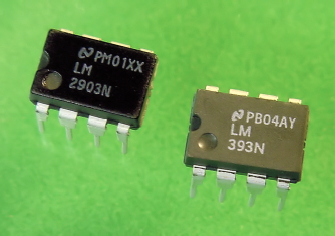
An analog voltage comparator chip (see Figure 15-1) is somewhat like a tiny voltmeter with built-in switches. It samples voltages at two points and turns on a switch if the first point's voltage is greater than the second point's voltage. It turns off the switch if the first point's voltage is less than the second point's voltage.
Like most chips, the comparator comes in different models and packages. To avoid intimidation, I chose the most common comparator with the fewest connections.
The least expensive model is the LM393. The LM293, LM2903, and LM193 are completely compatible with the LM393, with the added ability to operate at more extreme temperature ranges (below freezing and above 70° C). Feel free to choose any of those model numbers from any manufacturer.
The LM393's full title is "Low Power, Low Offset Voltage, Single Supply, Dual, Differential Comparators." That's a mouthful.
The "Low Power" term indicates that the chip doesn't use much electricity. That's valuable to a battery-powered robot.
The "Low Offset Voltage" term indicates that the chip can compare voltages that are very close to each other. That's going to be useful for the subtle differences in brightness encountered during line following.
The "Single Supply" term indicates that the chip operates using only one power source. A "Dual Supply" chip needs two back-to-back power supplies (or circuitry) to produce a positive, neutral, and negative. Some comparators are designed to be flexible, and can operate with either single or dual supplies, depending on how you connect them.
The "Dual" term indicates that there are two independent comparators in each chip. It's a two-for-one special! "Quad" chips contain four independent comparators.
The "Differential" term indicates the chip has circuitry to convert the comparison between two voltages in the input voltage range to a single digital output in the power supply's voltage range. For example, the chip's output voltage won't drop when the input voltages are very small, nor will it rise when the input voltages are very large.
Vital information regarding each chip or part is contained in a document called a datasheet. The datasheet is freely available from the manufacturer, often on their web site.
The datasheet begins with a brief description of the part, usually pointing out the features that have been improved over prior models. This is helpful in that it emphasizes attributes that professional engineers find particularly important (or that were previously lacking) in that kind of component.
The datasheet contains typical and maximum values for a selective list of electrical characteristics, such as: how much current it uses (battery drain), what voltage range it can tolerate, what temperatures it operates under, and so on. According to the datasheet, the LM393 can be powered from 2 V to 36 V. This generous range easily fits within a 9 V battery's voltage characteristics (5 V to 10 V).
There are a couple of significant issues revealed in the LM393 datasheets.
The first issue is that the LM393 can't compare voltages within the upper 1.5 V of the current battery level. So, if both test point's voltages are hovering in the 8 V range and the battery is 9 V, the comparator won't always make an accurate comparison.
The second issue is that the comparator can't guarantee that it has enough strength by itself to switch on a circuit that uses more than 6 mA. The datasheet indicates that the comparator can typically switch up to 16 mA, but you may legitimately receive a batch of chips with only 6 mA capability.
Both of these issues are compensated for in the robot's design, as will be pointed out later.
On chips, the metal wires sticking out are called pins. By far the most necessary information about a chip is how to hook up the pins to the rest of the circuit. The tiny chip case is too small a surface on which to print text descriptions or numbers for the pins. So, the datasheet provides an annotated illustration called a pinout, which shows all of the pins and their respective functions.
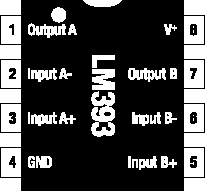
The pinout of the LM393 comparator chip is shown in Figure 15-2. There's a notch and/or a dot atop the physical chip as well as a notch atop the pinout illustration. Mentally number the pins starting from the notch, rotating counter-clockwise. This method makes it easy to universally reference any pin on a chip.
Tip
When a bunch of chips are placed on a board, the board should be designed so that all notches are aligned in the same direction. This way, a quick visual inspection reveals if any chips have been inserted backwards.
All chips have pins that receive power to run the chip. Think of a chip like an appliance: You need to plug it in to make it work. The power supply pins are the first two pins you should locate.
On the LM393, pin 8 and pin 4 receive power. Pin 8 is labeled V+, which means the positive end of the battery connects to this pin. Pin 4 is labeled GND, which means the negative end of the battery connects to this pin. At the end of this book is a list of the most common labels that indicate positive and negative power connections for chips.
Many chips have power pins on the same diagonal corners as the LM393. However, always check the chip's pinout on its datasheet to be sure.
Based on the chip's title, "Dual Comparators," we know that two comparators are included on this chip. Pins 1, 2, and 3 belong to the first comparator ("A") and pins 7, 6, and 5 belong to the second comparator ("B"). Notice that pin 1 (Output A) has the same name as pin 7 (Output B), pin 2 (Input A-) has the same name as pin 6 (Input B-), and pin 3 (Input A+) has the same name as pin 5 (Input B+) except that one set of pins is for comparator A and the other set for comparator B.
The comparators are truly independent: You can use them individually to measure completely different circuits or test points. The comparators function in the same manner, so once you have learned how to use comparator "A," then you know how to use comparator "B."
On the LM393, pin 1 is labeled Output A (see Figure 15-2). There is a solid-state switch inside of the chip that either connects the inside of this pin to the negative terminal of the battery or disconnects it.
Recall that a circuit turns off if either end of its power is disconnected. Therefore, if you connect the negative end of a circuit to pin 1 of the LM393, then the circuit can be turned on and off by the switch inside the LM393.
On the LM393, pin 2 and pin 3 are labeled Input A− and Input A+, respectively. These are connected to the test points that you'd like the chip to compare. If pin 2 has a higher voltage than pin 3, then pin 1 is switched to the battery (see left side of Figure 15-3). Otherwise, pin 1 is disconnected (see right side of Figure 15-3).
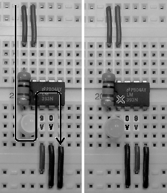
Figure 15.3. Left: When pin 2 has a higher voltage (for example, 9 V) than pin 3 (for example, 0 V), then pin 1 is switched to the negative end of the battery, thus allowing power to flow. Right: However, when pin 2 has a lower voltage (for example, 0 V) than pin 3 (for example, 9 V), then pin 1 is disconnected, thus preventing power from flowing.
Don't worry if this seems confusing. You can try it yourself with the comparator circuit coming up in this chapter.
Comparators are useful for many robot functions other than robot brains. They are often used to simplify sensor inputs by comparing the sensors to adjustable voltage levels. Table 15-1 shows the suppliers for the ordinary LM393 and for the more temperature-tolerant LM2903. Either is acceptable for the line-following robot.
Table 15.1. Dual Comparators
Supplier | Part Number | Price |
|---|---|---|
Mouser | 511-LM393N | $0.26 |
Mouser | 511-LM2903N | $0.26 |
Jameco | LM393N | $0.25 |
Digi-Key | LM393NGOS | $0.39 |
Digi-Key | LM2903NGOS | $0.39 |
The letter "N" follows each part number in Table 15-1. The final letter(s) in a part number usually signify the chip's package size, package material, and/or temperature tolerance. For parts manufactured by National Semiconductor, the letter "N" represents a dual inline package, otherwise known as a DIP.
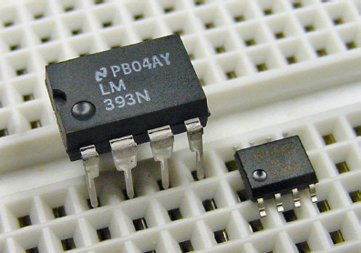
If you mistakenly purchase an LM393M ("M" not "N") chip, you'll find it encased in a different package. The SO-8 or SOIC narrow package won't fit into the solderless breadboard (see Figure 15-4).
The brightness comparator circuit connects to the balanced brightness-sensing circuit from the prior chapter. This is the brain that reads the photoresistor sensors and then controls the motors accordingly.
Instead of a formal schematic, the brightness comparator circuit is presented as a wiring diagram in Figure 15-5.

In a schematic, the dual comparators would not be drawn as a chip package. Instead, each comparator would be drawn separately as symbols near the parts they are comparing. The schematic ("package-free") technique reduces the number of lines crossing over the drawing. Pin numbers are usually not shown in schematics, which make the illustration independent of the particular chip package eventually implemented.
Unlike schematics, wiring diagrams present the layout as it looks in real life. Final pin numbers and package grouping are indicated. (While I was at it, I changed the resistors to look a little more realistic, instead of symbolic. I beg the forgiveness of any old-school electrical engineers.)
A schematic is better when you're designing the functionality of the circuit, without regard to the physical layout. A wiring diagram is easier to follow when you're actually assembling the circuit.
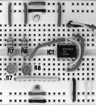
The rules for part labeling are reasonably flexible. Because the circuit in Figure 15-5 connects to another circuit containing resistors, I chose to number the new resistors where the last circuit left off (R7, for example). For ease of reading, I switched to using "LED" instead of "D" to label the LEDs. I also numbered the LEDs to match the resistors to which they're connected (LED7 and R7).
The LM393 is labeled as IC1 for integrated circuit #1. It's called an integrated circuit because the comparators are nothing more than an ordinary circuit of resistors, wires, diodes, and transistors squished into a single part. Got it? It's a circuit that's been integrated into a small package.
By the way, for proper connections, don't forget to pay attention to the notch in the chip.
Figure 15-5 is the first circuit presented in this book that has been complex enough that a few lines cross over each other. Sometimes the wires are connected to each other; sometimes they're just passing over.
A solid circle or dot appears on the wire near the arrow going to TP2. The dot indicates that those wires are connected.
A hop in a wire appears just above pin 5. The hop indicates that those wires aren't connected.
Some schematics and wiring diagrams don't bother with the hop. Instead they assume crossing wires aren't connected unless there's a dot. Depending on the author, you'll need to take a moment to acquaint yourself with his or her wire-connecting indicators.
The purpose of the brightness comparator circuit is to indicate which pair of photoresistors is receiving more light. The comparator chip accomplishes this by comparing the voltage at test point 1 to the voltage at test point 2; whichever has the lower voltage is receiving more light.
Both comparators in the LM393 are utilized. Comparator A compares TP2 (connected to Input A-) to TP1 (connected to Input A+) and turns on the LED7 (connected to Output A) when TP1 has a lower voltage (left photoresistors receiving more light). Comparator B compares TP1 (connected to Input B-) to TP2 (connected to Input B+) and turns on LED8 (connected to Output B) when TP2 has a lower voltage (right photoresistors receiving more light).
Pin 8 (V+) connects to positive power and pin 4 (GND) connects to negative power because the comparator chip needs to be plugged in to operate. Resistor R7 protects LED7 and resistor R8 protects LED8 from the full force of the battery, just as you used a resistor for that same purpose in the LED Power Indicator Circuit.
-- – 9 VDC power supply
R7, R8 – 2.2 kΩ resistor (red, red, red)
LED7 – Yellow LED
LED8 – Green LED
IC1 – LM393 (or equivalent) dual comparator
In the last chapter, you built the balanced brightness-sensing circuit on the right side of a solderless breadboard. You should build the brightness comparator circuit in the middle of the same board (see Figure 15-6).
Connect IC1 to the sensor test points (look ahead at Figure 15-7, if necessary) using reinforced jumper wire, rather than flat wire. The jumper wire crosses over other parts on the board, reaching the test points with ease. Additionally, the test-point ends of reinforced jumper wires can be pulled and positioned at other points for testing purposes.
Test point 1 (TP1) connects to IC1 input B-, which is then connected to IC1 input A+. Test point 2 (TP2) connects to IC1 input B+, which is then connected to IC1 input A-. So, both test points are connected to both comparators, except the connections are reversed on one of the comparators.
R7 and LED7 form an LED indicator circuit. As stated earlier, R7 is a current-limiting resistor that protects LED7 from the full force of the battery. This is the same simple LED circuit design that you use for the solderless breadboard power indicator. The big difference here is that the negative end of the LED circuit is connected to IC1 output A instead of the negative terminal of the battery.
When the comparator chooses to switch output A to the negative terminal of the battery, then power can flow from the positive terminal of the battery, through R7, through LED 7, through IC1 output A, and into the negative terminal of the battery. This flow of electricity turns on the LED. When the comparator chooses to disconnect output A, no power can flow and the LED turns off.
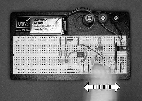
When you turn on power, either the green LED or the yellow LED will light. One at a time, cover each photoresistor with your finger. Try waving your hand across the sensors right to left and left to right (see Figure 15-7). The LEDs should blink back and forth as each side receives more or less light.
Now you have everything you need to tune the balance between the photoresistor sensor pairs by adjusting the trimpot (R2). Turning the dial far to one side should light one LED and turning the dial far to the other side should light the other LED. At some point, toward the middle of the dial, both LEDs should be lit or they should switch back and forth with only a slight turn of the trimpot dial to the left or right.
That's the balanced position. Although not strictly impossible, you're not likely to get both LEDs to light at the same time.
With balanced sensors, the LEDs should switch back and forth with even a faint shadow across the photoresistors. I noticed that the light reflecting off of my shirt was enough to activate the appropriate LED depending on which way I leaned.
What if your circuit isn't having fun at this point? If the circuit isn't working correctly, there are a bunch of tests you can perform to pinpoint the problem.
Make sure power is on. The LED power indicator circuit installed on the solderless breadboard should be lit. If not, disconnect the battery and measure its voltage independent of the circuit. If the battery's voltage is less than 6 volts, replace it with a fresh battery.
If the battery seems to have plenty of voltage when removed from the circuit, but voltage drops significantly when installed, the circuit probably has a short. This occurs when a positive wire is mistakenly connected to a negative wire somewhere on the breadboard. In that case, the power goes straight through the shorted wires without bothering to go through the routes containing all the electronic components. Carefully compare all of your wires to the schematics and photographs.
If the battery is fine and you don't have a short circuit, check that positive and negative connections to power are being supplied throughout the buses. To do this, connect the multimeter's black test probe and red test probe to each quadrant of the board to ensure that full battery voltage is being delivered.
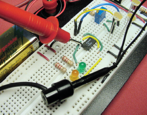
Check that positive power is being supplied to the top wire of R1, R7, R8, and IC1 V+ (pin 8). You can confirm this by connecting the black test probe to any negative bus and then (one at a time) touching the tip of the red test probe to the top wire lead of each of the resistors and to pin 8 of IC1 (see Figure 15-8). By touching the multimeter test-probe tip directly to the metal portion of the component that is supposed to be getting power, you can eliminate the possibility that the component wire is loose and not actually receiving power from the board.
Check that negative connections are being supplied to the bottom wire of R3, R6, and IC1 GND (pin 4). You can confirm this by connecting the red test probe to any positive bus and then (one at a time) touching the tip of the black test probe to the bottom wire lead of each of the two bottom photoresistors and to pin 4 of IC1. This is a slightly backwards test, since the red test probe stays in place and the black test probe moves to the points being tested. So, note that the meter displays 9 V (or whatever) if a proper connection exists, not 0 V.
For diagnostic purposes, the reinforced jumper wires connecting the comparator's inputs to the sensor test points can be redirected to ideal, unwavering test points. Connect one jumper wire to the positive bus and the other jumper wire to the negative bus to provide the highest-quality test signals (see Figure 15-9). One of the LEDs should light. You can then swap the jumper wires and the other LED should light.
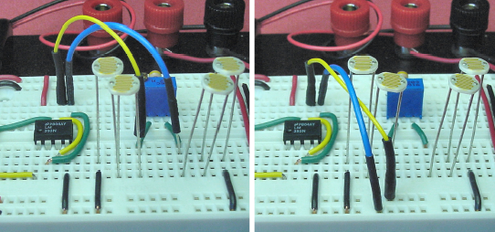
Figure 15.9. Moving the comparator input's jumper wire from the sensor test points (left) to the power supply buses (right)
With the jumper wires still connected to the buses (rather than the sensor test points), use a multimeter to test that the inputs of one comparator are receiving the voltages opposite from the other comparator. If the wires aren't reversed to the second comparator's inputs, then both LEDs will turn on at the same time and turn off at the same time.
Make sure neither LED is in backwards.
Currently, the sensors react to ambient (room) lighting. When installed on the robot, the sensors face down near the floor with most of the natural lighting blocked by the circuit board. By adding headlights, you can place the sensors underneath the robot and operate the robot in dim lighting or at night.
There's a special reason for adding a light source. As mentioned earlier in this chapter, the comparator can't compare voltages in the upper 1.5 V range of the battery voltage. When the photoresistor sensors are dark, their resistance gets very large. The large resistance causes the voltage at the test points to rise into the top 1.5 V. By adding headlights, the resistance remains below extreme values, thus staying away from the comparator's top-end weakness.
The headlight circuit is nearly identical to earlier LED circuits. The major difference here is that two LEDs are sharing the current (see Figure 15-10). This is very energy-efficient since some of the voltage that was being wasted as heat in the resistor is now creating light in the second LED. Because LED10 is using the same current flowing through LED9, the additional LED has no effect on battery drain.
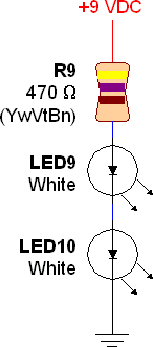
The only trick to keep in mind when stringing on additional LEDs is that the voltage of each LED needs to be subtracted from the battery total before selecting the value of the current-limiting resistor (R9). Here's that formula from several chapters ago:
(battery voltage - LED voltage) / (maximum LED current in mA / 1000) = minimum resistor
White LEDs need quite a bit more voltage than do red LEDs. About 3.1 V is common. If you don't have access to the datasheet for your white LEDs, the diode test on most digital multimeters can provide a decent estimate. (Unfortunately, some older multimeters may not be able to test diodes with voltage drops as high as 3 V.)
Because LEDs are tested at low current by the diode test of the multimeter, the true voltage consumed by the LED will be larger in an actual circuit. For example, the meter's diode test might display 2.6 V for a white LED that actually uses 3.1 V.
That's okay. The current-limiting resistor formula provides an improved safety margin if calculated with the lower voltage determined by the multimeter. Of course, always provide the actual LED voltage from the datasheets or actual circuit measurements if you can.
Here's the formula for the headlight circuit with two white LEDs:
(9 V battery - 3.1 V white LED - 3.1 V white LED) / (30 mA maximum current / 1000) = 93 Ω current limiting resistor
To be safe, I began testing the circuit with a more resistive value, 150 Ω. Even so, the white LEDs were blindingly bright! So, I continued to increase the resistor value until I was happy with the brightness, which also saves on power consumption.
Often, I'll adjust the brightness with a trimpot and then measure the trimpot resistance with a multimeter to determine the final resistor value to install. In fact, there isn't any reason you can't permanently install a 20 kΩ trimpot (like the variable brightness LED circuit) and alter the headlight brightness on the actual robot.
For the purpose of solderless-breadboard experiments, I settled on a current-limiting resistor of 470 Ω. Pick 330 Ω, 220 Ω, or even 150 Ω if you'd prefer brighter headlights. Remember that 93 Ω results in the absolute maximum current (30 mA), not the recommended current. LEDs are usually driven at currents between 2 mA and 20 mA.
Do not use any color other than white for the robot's headlights. For example, if you choose red headlight LEDs, then the robot will be unable to follow a blue tape line. The blue color of the tape reflects very little red, and the photoresistor sensors won't see any reflected light. White headlights provide the most universally satisfactory results.
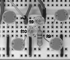
The headlights should go within the cluster of photoresistor sensors. There happened to be three empty solderless-breadboard columns in the center of my sensor circuit. If you don't have enough room, just shift some parts over. Ease of rewiring is a dominant feature of solderless breadboards.
Rather than extending a wire from the upper bus above the trimpot, I chose to add the headlights with power coming from the positive bus on the lower side of the breadboard. Figure 15-11 shows the current-limiting resistor (R9) connected to positive power and then going up to the anode of LED9. This is the same technique as the LED power indicator circuit uses.
With the headlights installed, the photoresistor sensors are no longer as sensitive to ambient shadows. That's a desirable feature for line following, as the robot won't start following deep shadows instead of the line. However, shadow ignoring takes some of the fun out of testing.
The sensors will likely need to be rebalanced. This is because the LEDs are lighting the photoresistors from behind. Some of the light is leaking through the backside of the photoresistor ceramic and contaminating the sensor values. For my finished robot, I tried to keep the heights of the LEDs the same as the heights of the photoresistors. I also painted the backs of the photoresistors black to prevent leakage.
Now that the circuit no longer needs ambient light, take the breadboard into a dark closet for hand-waving testing. Aren't you glad you're using a battery as a power source so that the breadboard is portable?
You've just learned that you can add extra LEDs without greater battery consumption. Hmm. The single yellow (LED7) and single green (LED8) LEDs look a little lonely.
Yellow and green LEDs usually require between 2.0 V and 2.2 V. We'll average it to 2.1 V for the formula. Let's see how many LEDs we can string in a row for a 9 V battery. Can the circuit support eight LEDs?
2.1 V LED × 8 = 16.8 V
No, obviously a 9 V battery doesn't have enough voltage for eight LEDs. What about four LEDs?
2.1 V LED × 4 = 8.4 V
Looks good. But wait! What happens when the battery runs down to 7 V? Oh well, not enough voltage for four LEDs when the battery runs down. Let's try three LEDs.
2.1 V LED × 3 = 6.3 V
Three LEDs are appropriate for a yellow and green LED voltage drop of approximately 2.1 V powered by a 9 V battery. Recall that only two white LEDs (not three) were used in the headlight circuit. That's because the white LED headlights require 3.1 V for each LED, for a total of 6.2 V.
The yellow and green indicator LEDs need to be visible from far away in standard room lighting. Therefore, the LEDs should be run near their brightest. That calls for a higher current, which is achieved by a lower resistance.
(9 V battery - (2.1 V LED × 3)) / (30 mA maximum current × 1000) = 90 W current limiting resistor
The most common resistor value above 90 Ω is 100 Ω. But, I'm going to use 150 Ω in case the battery voltage starts higher than 9 V. The higher resistor value provides a bit more safety. To double-check that you didn't make a math error at some point, plug the numbers into the formula for current presented a few chapters ago.
(V / Ω) × 1000 = mA
(9 V battery - (2.1 V LED × 3)) = 2.7 V remaining to be used by the resistor
2.7 V / 150 Ω current limiting resistor = 18 mA current
That's below the 30 mA maximum of the LEDs. But, there's a lurking limitation of the comparator. According to the datasheet, the typical current it can provide is 16 mA. The minimum current it assures to provide is a mere 6 mA.
The additional LEDs (much less the motors) can't be installed until this limitation of the comparator is addressed in the next chapter.
The line-following circuit is taking shape. The comparator makes a fine brain for this simple robot. The comparator is inexpensive, fast, and accurate without being complicated to employ. However, it does have some limitations that needed to be considered during design and testing.
The headlights provide consistent lighting for the photoresistor sensors. This allows the robot to run in the dark and it eliminates the issue of the comparator failing at high values. Frankly, the headlights also garner a lot of positive praise and attention for the robot.
The left and right LED indicators are working, which allows the sensors to be tuned. When you install three LEDs for each side, the robot's thoughts should be clearly visible from across the room. In the next chapter, you'll learn how you can interface the full sets of three LEDs to the comparator.