
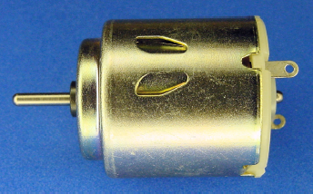
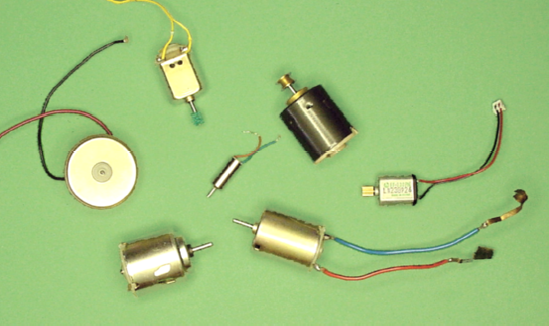
Motion is one of the primary differentiators between a robot and a computer. More robots get their motion from DC (Direct Current) motors than from any other mechanism (see Figure 17-1).
This chapter details the different varieties of DC motors and their characteristics. If you don't find this subject interesting, you can skim this chapter and move on to the next. Motors won't be selected and attached to the line-following robot circuit until the next chapter.
In an electric motor, electricity is converted to motion by magnetism.
Most people have played with a pair of magnets. Placing the magnets facing each other causes the magnets to attract and pull together. Turning one of the magnets around causes the pair to repel each other and push apart.
One magnet can attract with enough strength to drag the other magnet across a surface. This technique can be improved by adding a third magnet. The first magnet attracts the second magnet, while the third magnet repels from the rear.
When magnets are mounted around a pole, the combination of pulling and pushing can result in a rotating motion. A magnet on the shaft or pole is attracted to a magnet mounted nearby, while simultaneously being repelled by another magnet mounted on the opposite side. As soon as the shaft rotates to the magnet pulling it, the shaft magnet flips polarity and starts pushing away.
The key to making this mechanism operate is that flowing electricity can create a magnetic field. Instead of physically flipping over a magnet to change from attract to repel, the flow of electricity can be flipped forwards and backwards.
An iron-core permanent-magnet DC brush motor (see Figure 17-2) consists of two major sections: the stationary parts (stator) and the rotating parts (rotor). The cap, also called the endcap or assembly, at the end of the motor is connected to the stator and doesn't move.
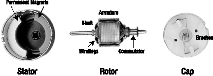
Figure 17.2. Guts of an ordinary DC motor: (left to right) stator with permanent magnets mounted near the outside walls; rotor with shaft, armature, windings, and commutator; and cap with brushes
The classic stator (the stationary part) includes two permanent magnets mounted opposite each other in a metal can (see Figure 17-3). The term "permanent magnets" indicates that the magnets remain magnetized even when the electricity is turned off. The magnetic field created by the electricity is going to push and pull against these two permanent magnets.
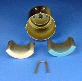
Figure 17.3. A pair of permanent magnets removed from the metal can. The clip in the foreground keeps the magnets from sliding together.
At high enough temperatures (Curie temperature), permanent magnets lose their magnetic field, resulting in reduced performance or even complete failure. Therefore, it's important not to abuse a motor by allowing it to overheat during use. Provide for adequate ventilation and, if possible, mount the motor body against other metal objects to provide a large thermal path to wick away the heat.
Interestingly, the metal container that makes up the body of the motor acts as a return path for the magnetic field. As such, less of the magnetic field is "leaked" into nearby components.
The rotor (the rotating part) is built around a shaft. The shaft sticks out the end of the motor body so that wheels, belts, fan blades, or gears can be connected to it.
To limit friction, only a small portion of the rotor touches the motor body. High-quality motors and large motors often include ball bearings at those locations to improve carrying strength and decrease friction.
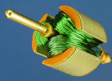
In the middle of the shaft is an armature containing many windings of wire (see Figure 17-4). The wire carries the electricity around and around an iron core in an oval loop. This increases the magnetic field that pushes and pulls against the permanent magnets on the stator.
Besides generating and transmitting the magnetic field, the iron core also dissipates and evenly distributes heat, allowing for hard running. However, the relatively heavy iron core makes it more difficult to start or stop the shaft because of inertia.
Note
Almost all motors have three or more windings. Motors with only two windings wouldn't necessarily rotate in the same direction at power up, nor would they necessarily rotate all the way around. For example: Initially the shaft would rotate toward the first magnet, but then the windings reverse, so it might rotate back the way it came. Hopefully, inertia would carry the rotor around in the direction it was already going.
At the ends of the armature are metal plates; each group is called a shoe. Motors with only a couple of shoes tend to start up unevenly and settle oddly when stopping. The irregular rotation is called cogging.
With power disconnected, it's easy to feel for cogging by gently turning the shaft with your fingers. Spin the shaft and watch it slow down. Better motors have smoother operation by increasing the number of shoes and by slanting the shoes' angles so one end overlaps the other relative to the magnets.
At the end of the shaft is a commutator (see Figure 17-5). It contains two or more segments to receive the electricity for the armature windings. Because the commutator segments are electrical contacts, it's important that they do not become soiled or coated in any non-conductive lubricant.

The commutator is necessary because power wires need to be attached to the armature windings. However, the wires can't be attached directly because they'd tangle up as the rotor turned. Instead, the commutator slides between metal brushes (see Figure 17-6) to make an electrical connection between the power wires coming in from the cap and the wire windings in the armature.
As the commutator rotates around, sometimes a winding is connected to the positive and negative terminals of the battery, and sometimes a winding is connected in reverse. This feature flips the electrical flow forwards and backwards. Thus, the magnetic field flips between attract and repel.
A great thing about the commutator mechanism is that the flipping automatically speeds up as the motor turns faster!
The "brush" term in "DC brush motor" indicates that the motor has brushes. The brushes connect directly to the battery or other power source. As stated earlier, the brushes press against the commutator to make the connection between the battery and the armature windings. The brushes must press firmly (see Figure 17-7) or else the electrical connection breaks and the electrical flow ceases.
There are a couple of downsides to brushes. First, the pressing of the brushes against the rotor adds friction, thus slowing down the motor and increasing heat. Second, the constant making and breaking of contacts generates electrical noise (like television static when a vacuum cleaner is run) and causes sparking. Last, but most important, the brushes wear out.
Even the most well-made, well-maintained brush motor is eventually going to encounter brush failure. Brush degeneration is caused more by sparking than by friction. High-end brush motors have capacitors to absorb sparks and the motors are designed to be serviceable to replace the brushes.
Recall that brushes are required to make the electrical connection to the windings because the windings are on a rotating portion of the motor. If the windings could be located on the stationary portion of the motor (the stator), then the power wires could be directly affixed to the windings. Such a configuration would eliminate the need for brushes.
This is the case with a brushless motor (see Figure 17-8). The magnet is on the rotor and the armature with windings is on the stator. No brushes are necessary.
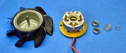
Figure 17.8. Guts of a brushless motor for a fan: (left to right) rotor with permanent magnet, stator with armature, pair of bearings, compression spring, and a retaining ring
Brushes are usually the first part to wear out on a brush motor. The lack of brushes on a brushless motor means dramatically increased lifespan and significant reduction in electrical noise. The lack of brushes eliminates sparking, and as such may be important in some scientific or hazardous situations.
For these reasons, brushless motors are very popular for computer fans. The brushless motor fan can run constantly for the life of the computer and the fan doesn't generate significant electrical noise that could interfere with the computer's digital operations.
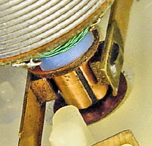
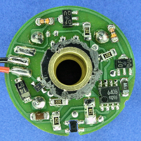
Since a commutator doesn't exist on a brushless motor, the windings are not mechanically switched as the rotor rotates. Instead, a non-trivial circuit (see Figure 17-9) monitors electrical current or the position of the rotor's magnet to electronically determine when to flip the flow.
Because of the voltage requirements of the chips and components on a brushless motor, it accepts a narrow range (around ±15%) of voltages for motor operation. On the other hand, the brush motor consists of wires and magnets that are usually perfectly content to accept the wide power ranges available from ordinary consumer batteries.
Aside from the more rigorous voltage requirements, other downsides of robot movement by brushless motors are that brushless motors tend to be less available, more expensive, and provide lower pushing power (torque). For these reasons, the robots in this book use brush motors.
The first motor type examined in this chapter was a brush motor containing an iron core. A coreless variation (also called ironless) exists that is very similar in all other aspects. Note that this is a brush motor, not brushless.
A coreless permanent-magnet DC brush motor (see Figure 17-10) consists of roughly the same sections, materials, and parts as the classic iron-core motor. The permanent magnets are still attached to the stator, although they're mounted towards the center rather than near the outside walls.

Figure 17.10. Guts of a coreless DC brush motor: (left to right) stator with permanent magnets mounted near the center; rotor with shaft, armature, windings, and commutator; and cap with brushes
The armature shows the biggest change. Instead of individual shoes and windings, the armature consists of overlapping windings. There is an empty space between the shaft and the windings so that the permanent magnets on the stator can slide in between.
Without the heavy iron core, the coreless rotor is much more nimble. Motor acceleration and deceleration is improved. Without the shoes, the rotation is very smooth: no cogging.
Then again, without the massive iron core, the motor can't dissipate heat as well. A high enough temperature destroys the motor by melting the plastic that holds the windings in shape. (Overheating should never occur during normal operation, as long as the robot provides adequate ventilation and power usage within manufacturer's specifications.)
The shape of the windings in a coreless motor provides greater efficiency. In an iron-core motor, the ends of the loops are not in the proper orientation to provide magnetic forces that contribute to the rotation. The thin edges of the coreless windings waste very little mass or resistance in non-productive directions.
DC brush motors are very easy to experiment with. You only need a motor, battery, and red and black alligator or IC hook jumper leads. No resistors or other components are necessary.
The motor must have only two wires or connector terminals. If the motor has more, it's probably not a permanent-magnet DC brush motor and therefore isn't appropriate for this experiment. You don't want a brushless, stepper, or servo motor, usually indicated by attached electronics or more than two wires.
Small, two-wire DC brush motors are all basically the same (see Figure 17-11). Some motors have long wire leads but other motors only have metal connectors. Some have gears or pulleys attached to their shafts, while others have plain shafts. Despite these cosmetic differences, they're all fine for this experiment.
It's easy to identify a DC brush motor if the selected motor is labeled something like "DC Motor," "DC 3V," or "DC 12V." You're unlikely to find a label that indicates the motor is a definitely a "brush" or "permanent-magnet" motor, because that's usually assumed unless the motor is marked otherwise. However, a motor marked "brushless," "servo," or "stepper" is definitely not correct for this experiment. Obviously it's reassuring to have a copy of the datasheet for the motor just to be sure, but it isn't necessary.
You can purchase ordinary DC motors for around $1. Table 17-1 lists a couple of sources for assorted grab bags. You can purchase individual DC motors from almost any electronic store or catalog company. You can also salvage motors out of toys.
You must exercise a little care when selecting the battery. Most toy motors are designed for operation at 3 V. Although you can connect a 3 V motor to a 9 V battery for a dozen seconds or so, the motor starts heating up (you can feel it). Give the motor a minute to cool off between 9 V bursts. There are plenty of rugged DC brush motors designed to continuously accept 6 V, 12 V, 24 V, and higher.
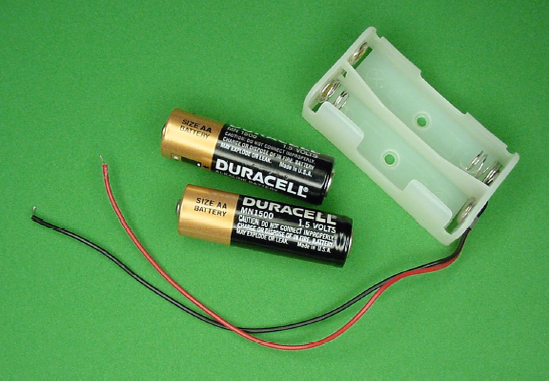
If you only have a 9 V battery, that will do for this experiment. If possible, check with the voltage setting on your multimeter to select a 9 V battery that has run down a bit in voltage. Even better, get two AA-size cells and a holder (see Figure 17-12); they'll provide the appropriate 3 V.
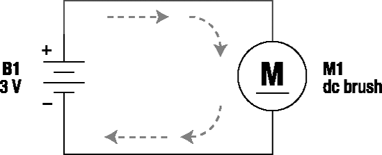
The schematic for the simple DC motor circuit is quite simple, indeed (see Figure 17-13). B1 is 3 V of battery power and M1 is a DC brush motor. Note that the schematic symbol for a DC motor is an underlined letter 'M' within a circle.
Connect one end of the red jumper lead to the positive battery terminal and the other end of the red jumper lead to the positive terminal of the motor (see Figure 17-14). If the motor isn't labeled with positive or negative, then select the red wire coming from the motor. If no wires are coming from the motor or neither is red, pick either wire or terminal. If you connect the motor backwards, no big deal, it runs backwards.
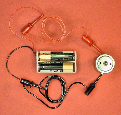
Connect one end of the black jumper lead to the negative battery terminal and the other end of the black jumper lead to the negative terminal of the motor. The motor should start spinning! If you swap the ends of the red and black jumpers on the battery terminal, the motor spins in the reverse direction.
DC motors have many significant attributes worth examining. Which characteristic matters the most to you depends on how you are going to use the motor. Some of the more technical material may only matter to you in more advanced stages of your hobby.
A popular unit for measuring motor speed is RPM, which stands for revolutions per minute. This indicates how many times the motor will rotate the shaft (and anything connected to it) in a minute.
For example, the second hand on an analog clock rotates around once every minute (see Figure 17-15), for a speed of 1 RPM. If you want to get a sense for 1 RPM, just watch a clock. That's slow!
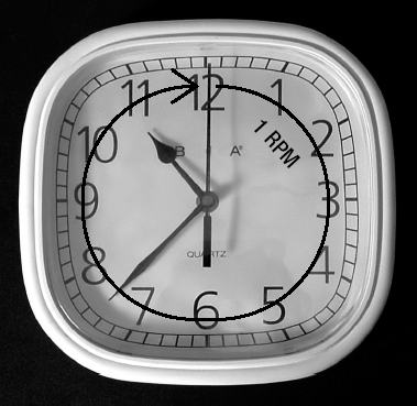
Most DC motors spin at 3000 RPM to 8000 RPM. At the high end, that means the motor can rotate its shaft around 8000 times before a clock's second hand completes a single rotation. That's really fast!
Initially it may seem that faster is better, but that's not the case. For a line-following robot with slow-reacting sensors, fast speed could drive the robot off the line before the brain has time to react. On the other hand, too little speed could put your audience to sleep. Sandwich runs its motors at around 137 RPM.
Even though DC motors naturally spin at thousands of RPM, there are some good ways to alter the final output speed. In fact, designers are rarely forced into accepting the base speed of a motor. Information on an effective speed manipulation technique, gear reduction, appears at the end of this chapter.
Common robot wheel-driving speeds are between 40 RPM (precision movement) and 250 RPM (very fast). Cooling fans usually rotate at between 3000 RPM and 6500 RPM. Robot arms or directional sensors are often rotated well below 60 RPM.
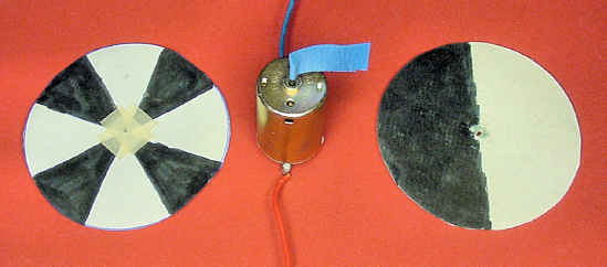
By attaching a piece of tape or half-colored disc to a motor shaft (see Figure 17-16), you can measure the number of times the shaft rotates in a minute. Depending on your brain-eye coordination and propensity towards distraction, you are unlikely to be able to count speeds faster than 120 RPM by eye. Even toy motors running at 3 V can quickly make the target a blur.
However, you can measure even tens of thousands of RPM very accurately by a device called a tachometer. For short, it's often called a "tach," which is pronounced "tack."
Most cars have tachometer displays built into the dashboard. The gauge usually goes from 0 to 8, with numbers over 6 in the red portion of the dial. Multiply the number by 1000 to get the RPM. Therefore, the gauge is actually displaying 0 RPM to 8000 RPM.
"Contact" tachometers are physically connected to the motor shaft, which can reduce speed, thus providing an inaccurate reading. "Non-contact" tachometers usually esmploy brightness sensors to detect rotations. Some non-contact tachometers, like those placed on car hoods during emissions testing, take advantage of the expected period of vibrations.
Figure 17-17 shows a DC brush motor running at 4038 RPM being measured by a homemade tachometer. The motor spins a half-black and half-white disc attached to the motor shaft. A motionless image of the disc is pictured at the far right of Figure 17-16.
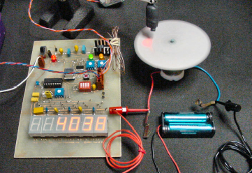
The tachometer illuminates the rotating disc with an LED. The tachometer sees the disc change from light to dark by the amount of light reflected into a brightness sensor. A chip on the tachometer counts the amount of time it takes the disc to complete a light-to-dark-to-light transition (one rotation). This measurement permits the tachometer to mathematically determine the speed.
Professional handheld laser tachometers can be purchased for as low a price as $100.
Poster tack or mounting putty is a rubbery clay-like substance. This reusable putty is reasonably sticky yet it rarely leaves residue and it doesn't dry out. It's primarily used for cleanly attaching posters to walls.
I find the putty to be ideal for holding motors upright while experimenting. The putty also quickly affixes the testing disc to any motor shaft. You may be able to spot that I used a bit of putty for both purposes on the top and the bottom of the motor in Figure 17-17. Of course, the putty is too soft for permanent mounting in a robot.
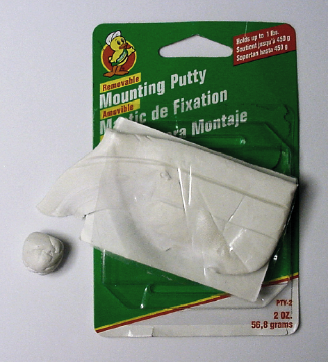
Mounting putty is available at local hardware stores, office supply outlets, and even some supermarkets. Blue, white, and yellow colors are available.
The metric unit for angular velocity is radian per second, or rad/s. Even though it doesn't appear often in advertisements, rad/s sometimes shows up in datasheets. For motors, RPM and rad/s are used to measure the same thing, but rad/s is an internationally accepted unit in the metric system.
To convert RPM to rad/s, multiply by 0.10472 (which is an approximation of π/30).
RPM × 0.10472 = rad/s
137 RPM (Sandwich's motors) × 0.10472 = 14.34664 rad/s
To convert rad/s to RPM, multiply by 9.54929 (which is an approximation of 30/π).
rad/s × 9.54929 = RPM
14.34664 rad/s (Sandwich's motors) × 9.54929 = 137 RPM
Torque is the amount of twisting force that can be performed by a motor. This indicates how heavy of a load the motor can turn. Torque is very important as it determines how weighty the robot can be, how steep of a hill the robot can climb, and how much the robot can push or pull.
Speed and torque are not the same things. An electric screwdriver has large amounts of torque so that it can drive a screw into or out of strong material. But the screwdriver has fairly slow speed because otherwise the tip of the screwdriver would likely slip out of the groove at the head of the screw.
Contrast the electric screwdriver with a computer fan. The computer fan has lots of speed, but the fan blade can be stopped or jammed easily (very little torque). Or take the circular saw, which has a powerful combination of speed and torque.
It is easier to hold an object by your sides than it is to hold the object with your arms outstretched. Therefore, torque must be measured in both how much mass can be turned and how far away that mass is.
Motor torque is specified in newton meters (N·m). The little dot between "N·m" is often omitted.
Lots of other units specify torque, although they're all measuring the same thing. A common unit is pound-force foot (lbf-ft). Some imperial-system terms were specified in reverse to distinguish between torque and work, but motor advertisements specifying "foot pound" mean the same thing as "pound foot," and so on.
The letter "f," for force, is often omitted from advertisements. So, instead of seeing lbf-ft, the motor could be listed as lb-ft, ft-lb, or even ft-lbf. They all mean the same thing. To recognize a motor's torque specification, look for any force/mass (like N, g, lb, or oz) combined with a length (like m, cm, ft, or in).
Table 17-2 lists the other most-common torque units and how to convert them to N·m. For example, to compare a 3.2 lbf-ft torque motor to a 4 N·m torque motor, multiply 3.2 lbf-ft by 1.355817948 to get 4.338617434 N·m. Based on that conversion, the 3.2 lbf-ft motor has a greater maximum torque than the 4 N·m torque motor.
Table 17.2. Table for Converting Between Other Common Torque Units and the International Standard N·m
Known Unit | Multiplier | Desired Unit |
|---|---|---|
kgf-m | x 9.806 650 029 | = N·m |
lbf-ft | x 1.355 817 948 | = N·m |
lbf-in | x 0.112 984 829 | = N·m |
kgf-cm | x 0.098 066 500 | = N·m |
N·cm | x 0.01 | = N·m |
ozf-in | x 0.007 061 552 | = N·m |
mN·m | x 0.001 | = N·m |
gf-cm | x 0.000 098 066 5 | = N·m |
dyn-cm | x 0.000 000 1 | = N·m |
Table 17-3 shows how to convert from N·m to the other most-common torque units. For example, to compare a 0.4 N·m torque motor to 50 ozf-in torque motor, multiply 0.4 N·m by 141.6119327 to get 56.64477308 ozf-in. Based on that conversion, the 0.4 N·m motor has a greater maximum torque than the 50 ozf-in torque motor.
Table 17.3. Table for Converting Between the International Standard N·m and Other Common Torque Units
Known Unit | Multiplier | Desired Unit |
|---|---|---|
N·m | x 0.101 971 621 | = kgf-m |
N·m | x 0.737 562 15 | = lbf-ft |
N·m | x 8.850 745 795 | = lbf-in |
N·m | x 10.197 162 1 | = kgf-cm |
N·m | x 100 | = N·cm |
N·m | x 141.611 932 7 | = ozf-in |
N·m | x 1000 | = mN·m |
N·m | x 10 197.162 1 | = gf-cm |
N·m | x 10 000 000 | = dyn-cm |
I find gf-cm the most graspable torque unit for small robot motors. Table 17-4 lists other common torque units and how to convert them to gf-cm. (You can reach the same results by converting a unit to N·m with Table 17-2 and then converting N·m to gf-cm with Table 17-3.)
A full can of soda is about 380 grams. A motor with 380 gf-cm of torque can rotate a 380-gram mass connected 1-centimeter away (380 gf × 1 cm = 380 gf-cm).
Torque isn't restricted to a 1-centimeter distance. A 9 V battery is a little over 38 grams. That same motor could rotate 38 grams connected 10 centimeters away (38 gf × 10 cm = 380 gf-cm). Torque allows for less mass farther out or more mass farther in, as long as the numbers multiplied together are less than or equal to the motor's torque.
This has practical implications. If you build a robot arm that the motor can't move, you can either get a motor with higher-rated torque, you can shorten the arm (the length), or you can reduce the mass (the weight).
The example of a soda can connected one centimeter away isn't totally accurate because the can itself is longer than one centimeter. In reality, you need to be careful to determine exactly the force from a large or odd-shaped object. At the very least, measure from the center of the mass to help determine the distance the mass is "connected" as far as the torque is concerned.
The proper calculations involved in determining the minimum torque needed for a robot-driving motor are complex. It depends on where the mass is located, if the mass shifts, how steep of an angle the robot must climb, and the other forces being generated against the robot (such as an attacking opponent).
Luckily, torque is not a major concern for motors that drive the wheels of lunchbox-size robots. If the speed (RPM) and other factors (availability, price, dimensions, weight, voltage) of the motor fit the design, torque is likely to be acceptable.
You can always begin an experiment with one kind of motor and then swap in a lower-or higher-rated torque motor until you're happy with the outcome. Compare advertised motor torque specifications using the torque conversion tables provided in this chapter.
Extra motor torque isn't a problem as long as the other factors of the motor meet your robot's needs. In fact, it's best to leave a safety margin by providing motors rated at a higher torque. If the motor can provide triple or more of the necessary torque continuously, not only will the robot run cooler and more efficiently without damaging the motors, but also the robot will have strength to spare if you decide to add new parts or loads.
Be aware that other parts on your robot are likely to break (wheels, gears, treads, body structure) if they are not strong enough to support the forces acting on the robot. That is, even with properly rated motors, the physical energy must be transmittable through wheels, treads, or legs.
In datasheets and advertisements, motor specifications are disclosed at "nominal voltage." That's the voltage the manufacturer expects the motor to run at. Common voltages are 3 V, 6 V, 12 V, 18 V, and 24 V. Larger motors can support even higher voltages.
Most DC brush motors can be run between 50% and 125% of their nominal voltage. For example, a 12 V motor could be run at any voltage from 6 V to 15 V. Below 50% of the nominal voltage the motor may not turn. Above a certain voltage the motor may overheat or breakdown.
That being said, many scientific or high-precision motors run at even 10% of their nominal voltage. At the other extreme, many motors in combat robots are run at 200% of their nominal voltage.
Try to pick a motor that has a voltage that most closely matches your batteries. Unless you're a particularly crafty expert, don't design a robot with a 9 V battery and 3 V motors. Likewise, don't build a robot with a 3 V battery and 24 V motors.
The greater the voltage, the greater the speed, up to the maximum permitted by the motor. For example, if you have a 12 V motor and it is running a little too slow, try 14 V. If it is running too fast, try 9 V.
Speed changes in direct proportion to the change in voltage. Figure 17-19 shows a graph of a test performed on an escap-brand motor (made by Portescap). As voltage is increased by 1.5 volts at a time, the speed increases by about 530 RPM. Of course, the amount of speed change in other motors will be different.
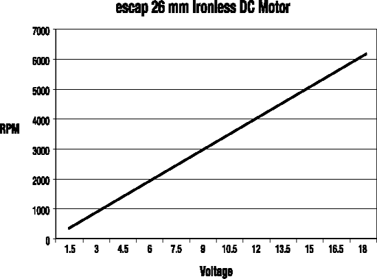
The escap motor was received second-hand, so I don't know the nominal voltage. Assuming 12 V, this high-quality motor exhibited operation from 12.5% voltage to 150%. I would have tried up to 200%, but my previously mentioned mounting putty starting flying all over the room at 6000 RPM.
Unfortunately, controlling speed with voltage only works well when you have the ability to swap in different batteries. Furthermore, the voltage to the escap motor would need to be around 0.39 V to provide the 137 RPM speed needed by Sandwich. There are better ways (gears and pulse-width modulation) to vary the speed of the motors than directly controlling the voltage provided to them.
As the robot wanders around, the batteries will drain. As the batteries drain, their voltage decreases. As you've just learned, as the voltage decreases, so does the motor speed.
For many robots, the loss of speed is inconsequential to viable operation. A line-following robot still works. In fact, the line-follower will be able to turn tighter corners and complete more difficult courses since the brains and sensors can more easily outpace the motors.
For other robots, the loss of speed can be disastrous. Robots that follow preset courses using timing no longer operate because the slower motor speed doesn't carry them the same distance in a same amount of time. If necessary, the declining speed can be counteracted, such as by receiving feedback as to the actual extent the wheel has turned.
Recall that the amount of current flowing through a circuit has a direct impact on how long the batteries last. Look out! Electric motors really suck up the juice.
You may spend hours tweaking resistor values on your LEDs and circuits. You're proud to save a few mA here and there. And then, you discover that even a single motor drains more than the entire rest of the robot combined.
Larger DC motors rate in the amp range, such as half an amp to hundreds of amps. Lunchbox-size robot motors consume a fraction of that amount, with a usual range from 4 mA to 250 mA for each motor.
The quality of the motor makes a big difference. Case in point: When connected to 3 V, a toy motor (see Figure 17-20) uses 125 mA but an escap motor uses only 4.5 mA. At 12 V, the escap motor has superior speed and torque, yet still only uses 7 mA.
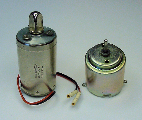
To be fair, the escap motor costs 10 times as much, weighs 2.5 times as much, has ¼ the RPM at 3 V, and is about 25% longer than the toy motor. But, that low current draw of 4 mA to 7 mA is enormously appealing.
The amount of current consumed by a motor changes a lot during operation. As you'll soon see, the amount of current flow during start-up and stall is very different than no-load or load current.
The exposed motor guts presented early in this chapter showed that an ordinary brush motor doesn't contain any resistors or other similar parts inside of it. If you connect your multimeter in Ω mode (like when you measure resistors) to the two leads of a motor at rest (not spinning), you'll see there is a resistance.
Note
It isn't always possible to accurately measure the resistance of assembled motor coils using a multimeter. If the brushes are dirty or aren't making full contact or if the motor is under mechanical stress, the resistance values vary wildly.
Although wire can usually be thought of as having practically no resistance, the lengths of wire in a motor are long enough to act like a resistor.
Big motors have a thick wire inside, so big motors usually have tiny resistances, below 1 Ω. However, small motors have an extremely skinny wire, which is more resistant. Small motors have resistances usually between 6 Ω and 150 Ω.
At the moment power is applied to a brush motor at rest, the only things resisting the flow of electricity are the coils of wire in the rotor. Here's a worst-case formula:
(V battery / Ω motor coils) × 1000 = mA maximum current
escap example: (12 V battery / 16.4 Ω motor coils) × 1000 = 732 mA
Luckily, it's not that bad. There's a property called inductance that doesn't like to see a sudden change in current. So, although there is a nasty blast of current (see Figure 17-21) in the interval of start-up, it isn't quite as bad as the simple formula indicates.
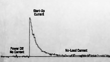
The surge of electricity from the battery can be a problem for any electronics attached to the same battery. It is possible for chips and LEDs to be temporarily starved while the battery feeds the engaging motors. There are simple techniques, like adding capacitors, which provide local energy storage during the energy crisis.
Depending on the motor, the start-up current diminishes to no-load current in about one-tenth of a second.
As the motor comes up to the appropriate RPM based on the voltage provided, the amount of current flowing through the motor declines. Why? Because it is easier to keep something spinning than it is to get the thing spinning in the first place.
Let's take the escap motor as an example. At first, a lot of power is applied to make the rotor change from 0 RPM to 4000 RPM. But, thereafter the rotor has some inertia and is going the desired speed. The only continued electrical investment needed at that point is to overcome a bit of friction, noise, vibration, and sparking.
Let's say the motor would drop down to 3900 RPM in a tenth of a second if power were disconnected. So, in that tenth of a second, a motor with power needs only change from 3900 RPM to 4000 RPM, rather than 0 RPM to 4000 RPM. It obviously takes less power to speed up 100 RPM as opposed to 4000 RPM, which is why a spinning motor uses less power than a motor starting up.
When a motor is up to speed and the motor shaft is not connected to anything, the amount of current flowing is called the "no-load" current. This is the least amount of current the motor uses.
No-load current is easy to measure. Simply connect your multimeter in amp mode (like when you measured current in the LED Circuit) between the battery and the motor. When the number settles down after a second or so, that's the no-load current.
At 12 V, the escap motor has a no-load current of a mere 7 mA. It's as though the coil resistance went from 16.4 Ω at power-off to 1714 Ω at no-load spinning. An almost magical property called back EMF or induced EMF (Electromotive Force) resists the flow of more electricity than is needed to keep the motor going.
The important thing to keep in mind is that an already-spinning motor takes less power than getting a motor to start spinning. That's no-load current.
As force is added to the shaft of the motor, by attaching wheels or driving a robot uphill, the amount of current increases. Even attaching an RPM measuring disc to a motor adds enough drag that the motor consumes a bit more current than it did by itself.
The increase in current stays at that level as long as the load is there. When the load is removed, the motor current decreases.
As more and more of the motor's maximum torque is required to rotate more and more massive or forceful loads, the motor's current increases until the motor doesn't have the twisting strength to turn anymore. When the motor stops turning but is still receiving power, that's called a stall.
Since power is fully applied but the motor's rotor can't turn, almost no inductance is generated. This is because there isn't a change in current like when the motor was starting to turn. Also, no back EMF is generated because the motor would choose to go faster if it could. It's physically stopped from turning; it's not settled into its natural speed-per-volt ratio.
A stall is the very worst state for a motor!
During a stall, the only thing resisting the current is the resistance of the coil windings. When the motor shaft is held in place, the current flow in the escap motor rockets from 7 mA to over 600 mA.
That's bad for battery life, but worse for the motor. None of the electricity is being converted to motion through magnetism. Almost all of the electricity flowing through the motor coils is producing heat. The motor could be destroyed by heat if allowed to stay in a stalled state for too long.
The dangers present in a stalled motor explain the phenomena of robot builders leaping to save their creations when the robot gets stuck against a chair leg or a wall. If the wheels aren't turning but the motors have power, those motors are stalling.
Robots can be designed to watch their wheels and to pulse, reverse, or cut power if the wheels aren't turning. Fuses or self-resetting circuit breakers can turn off power in the event of large current drain due to a prolonged stall. Adequate ventilation helps cool down the motors if they do stall briefly. By choosing strong enough motors, the safety margin should provide more than enough torque to avoid stalling during expected loads of operations.
Here are some thoughts on planning for the electrical-current consumption of motors:
The robot's chips must be able to continue working during the start-up current draw of the motors. This usually means adding some capacitors. However, Sandwich has only one comparator chip whose datasheet says capacitors aren't necessary.
If a robot's motors are turning on and off a lot, like they are in the line-follower, you can assume the batteries will deplete faster due to start-up current. No big deal. However, if the motors stay on for longer periods of time, you can almost ignore the start-up current's effect on battery life.
No-load current tells you the absolute minimum current that the motors consume. This is one of many criteria for comparing motors, but a "no-load" situation is unrealistic for calculating battery life.
Load current is a much more practical value to determine battery life and heat dissipation. Of course, the robot will almost be complete, with motors and wheels installed, before you can use the multimeter to get a load-current reading. You'll also look a little weird following a robot around your house, bent over with a multimeter.
Robust robots should be designed to be able to continuously provide more than the start current or stall current of all motors. This takes care of worst-case scenarios. The impact of the design is negligible in that the electronics and batteries need to be a little beefier and the motors must be properly ventilated. The robot you spend tens of hours making (if not hundreds of hours) will be safe and capable.
Regardless of how efficiently a robot utilizes a motor, the motor itself has an efficiency associated with its ability to convert electrical energy into mechanical energy. Well-designed motors can be as much as 90% efficient. That means almost all of the electricity is turned into useful motion, with only 10% wasted.
Wasted electricity can take many forms, such as noise, vibration, sparks (light, sound, heat, physical damage), and magnetic fields. However, the motor expends most wasted electricity as heat. Therefore, a more efficient motor not only permits the robot's batteries to run longer, but also permits the motor itself to run cooler.
Because motors usually guzzle the largest portion of the robot's power supply, more efficient motors may be worth the extra cost. This extends the robot's run time before needing a recharge.
Toy motors hover at around 30% efficiency or less. Precision motors, like escap or Maxon, are around 75% efficient or better. The motor's datasheet provides a specific number along with a curve representing the efficiency under various speeds and loads. Motors are usually most efficient when carrying a load about 1/7 their maximum torque.
A squeaky motor can be annoying. Perhaps it just needs some lubrication. Maybe the motor has a defect. Or, perhaps the motor is wearing out.
In any case, the unpleasant grinding or squealing of motors can be a detractor from your robot. Before ordering a large quantity of a particular motor, it is worth sampling a couple to make sure they don't have any unadvertised negatives such as noise.
Motors that squeal can often be quieted (with a bonus of increased performance) by applying a tiny dab of light oil to the places where the shaft rests on the motor body. This is normally at the front and back of the motor body, just where the shaft sticks out.
Don't apply oil or other lubrication if the motor is working correctly, as the existing lubrication may be a special formulation or it may be incompatible with your choice of lubrication.
Electrical noise is not the same as audible squealing and squeaking. Electrical noise appears as rapid, spiked fluctuations in voltage in attached circuitry or nearby components. The most common human experience of electrical noise is static on a television when someone is vacuuming.
Robots can have big problems with electrical noise. Noise can scramble information as it is being communicated throughout a circuit board. The chips can reset as though power had been turned off and on.
The affected board doesn't even need to be in close proximity to a noisy motor. Electronics and motors sharing the same power source (battery) can transmit the electrical noise throughout all attached circuit boards.
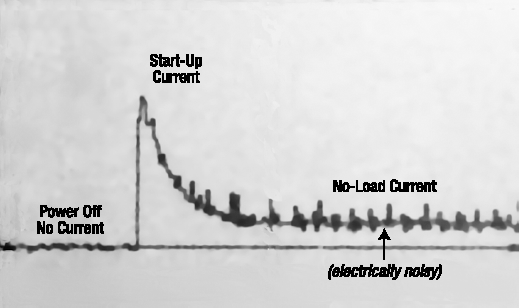
More efficient motors tend to produce less electrical noise. (Likewise with motors that have built-in capacitors.) Figure 17-22 shows lots of spikes generated by the brushes connecting and disconnecting from a toy motor's rotor commutator segments.
Little noise ripples do exist even in the power-off state, but contrast them with the no-load spikes. Look back at Figure 17-21 and notice how small the no-load spikes are on the escap motor—especially relative to the power-off-state spikes in that same figure.
The capacitors that protect chips during motor start-up can also dampen electrical noise generated during normal motor operation. Some robot designers go farther by providing separate batteries for the motors and electronics. The designers add special optical isolators to communicate commands to the motors without a common electrical connection.
Until recently, none of my robots had ever suffered a glitch due to motor noise. My circuit boards tend to have a lot of capacitors and I tend to choose nicer quality motors whenever possible. It could also be that my robots are fairly small, so the amount of wasted power going towards electrical noise is not enough to trip up modern chips.
I solved the one problematic experience that I encountered with motor noise by switching from an ultra-low power chip to a normal (not as efficient) chip. Despite my best efforts, I could not reduce the noise coming from the inexpensive motor, so I simply opted for more tolerant electronics.
Motors weigh a lot. It wouldn't be unexpected for motors to represent a third of a robot's mass. Sandwich's motors are 37% of the line-follower's mass.
When building a robot for a contest or some application where the robot's mass is restricted to a maximum, avoid selecting motors with a combined weight of more than 40% of the total. Otherwise, there won't be enough weight available for the batteries or a structurally decent robot body.
DC brush motors come in a variety of shapes and sizes. As long as the other characteristics of the motor aren't totally out of whack, the physical size of a motor is probably the most important characteristic.
Motor size usually dictates the robot's size, rather than the other way around. Many builders snap up decent motors whenever they appear in surplus sales. As such, builders have a private stash of motors that they select from at the beginning of a project. The motors available then dictate the minimum dimensions of the robot body. The maximum torque of the selected motors then dictates the maximum weight of the total robot.
When examining an advertisement or datasheet for a motor, here are the things to think about.
- Speed
Does the RPM at the given voltage (or scaled proportionally) meet the robot's needs?
- Torque
It is unlikely that you'll be sure of your robot's exact torque needs. Yet, torque is still useful in choosing between otherwise equal motors in a potential purchase. One way to get a feel for the torque of a motor you are considering is to compare it with a known motor that has either been adequate or inadequate for you in the past.
- Voltage
Is the motor's specified voltage within 50% to 125% of the voltage the robot's batteries are prepared to provide? Consider the voltage of the batteries when fresh and when declared exhausted.
- Current
Can the robot's electronics handle the maximum (start up/stall) current? How long will the battery last based on the minimum current (no-load) of the motors?
- Efficiency
If the speed and torque of the motor is a good match for the robot, then the highest efficiency motor has, by definition, the lowest current for a given voltage. High efficiency suggests high quality, which may be true for other characteristics of that same motor.
- Audible Noise
Although every motor can be expected to generate some audible noise, excessive noise can indicate a problem or, at the very least, be an irritant.
- Electrical Noise
Every brush motor generates some electrical noise, but it shouldn't be so bad as to interfere with the electronics. Motors that are high efficiency or have multiple windings/commutator segments are less likely to disturb circuitry. Liberal use of capacitors in the robot's circuitry helps immensely.
- Mass
Pick a motor whose weight can be supported by the body materials you're comfortable using. Where mass-limit rules apply, watch out for running out of weight due to motors, thus being forced to skimp elsewhere in the robot.
- Dimensions
The motors must fit into the selected robot body, or else select a body for the chosen motors. Unless gearing or a fancy drive train is included, motors are usually positioned end to end, thus dictating the minimum width of the robot.
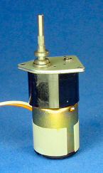
Gearhead motors are sometimes called gearmotors or geared motors. They usually consist of a DC brush motor (either iron core or coreless) with a gearbox attached to the shaft. You can immediately identify a motor as a gearhead by two distinct segments connected together (see Figure 17-23).
Gearhead motors almost always reduce the speed of the motor in exchange for increased twisting force (torque). Recall that at optimal voltage, a DC motor rotates way too fast to be useful to most robots. With a gearhead reduction, the robot can carry heavier loads while moving at the desired speed.
Because the DC motor still has the same two wires coming from it, a gearhead motor is just as easy to use as a plain motor.
A spur gearhead motor (see Figure 17-24) begins with an ordinary DC motor. A series of smaller gears touching larger gears is placed within a rigid frame called a box. The gears are usually greased and then protected with a cover to prevent dirt, grime, and stray wires from getting jammed in the works. Screws hold the gearbox tightly on top of the DC motor.
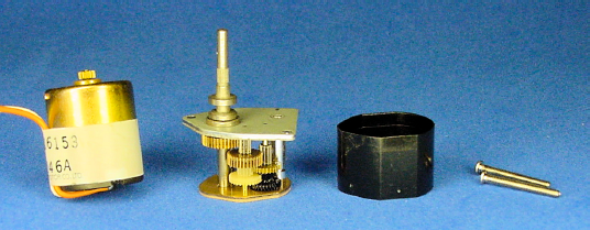
Figure 17.24. Spur gearhead motor consists of: (left to right) DC brush motor, spur gearbox, gearbox cover, and joining screws.
A spur gear is a circle with pointy teeth on the perimeter. The teeth push against the teeth of other gears to make them move (see Figure 17-25).
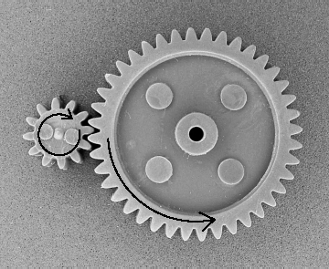
Figure 17.25. Smaller spur gear with 12 teeth rotates only 12 teeth of the larger spur gear, which has 40 teeth total
On a spur gearhead motor, the DC motor shaft turns the first smaller gear against the first larger gear. Because the smaller gear has fewer teeth, each time the smaller gear rotates once the larger gear only rotates partially around.
For example, if the smaller gear has 12 teeth but the larger gear has 40 teeth, then the smaller gear rotates around three and a third times (40/12) before the larger gear has been pushed around once. In this example, if the smaller gear were connected to a motor running at 6000 RPM, the larger gear would only be spinning at 1800 RPM.
smaller gear RPM × smaller gear teeth / larger gear teeth = larger gear RPM
6000 RPM × 12 teeth / 40 teeth = 1800 RPM
Three and a third teeth push the same "distance" that only a single tooth previously pushed. If each little twist comes from three and third teeth pushing, then the twisting force (torque) of the larger wheel has been increased by 3 1/3 times.
This seems fair. If the motor is being fed the same voltage and the same current but only producing 1800 RPM, the missing energy must be going somewhere. It goes into increased torque. By placing a series of smaller gears and larger gears together in the gearbox, the motor speed can be reduced more and more with torque increased more and more.
A shaft is connected to the last gear. The end of this new shaft appears out the top of the gearbox for wheels and things to be connected to it. This new shaft out of the gearbox replaces the old shaft coming out of the motor.
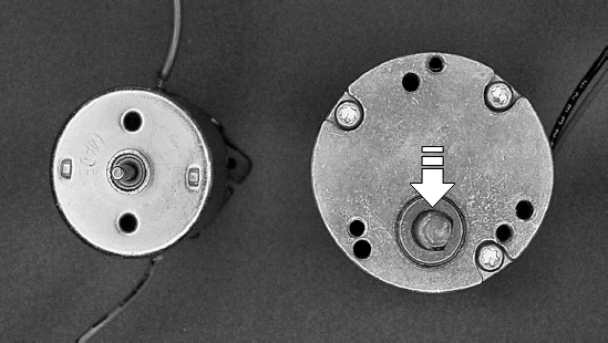
When examining a motor, if the shaft doesn't come out of the center, it's likely that the motor is a gearhead motor (see Figure 17-26). Standard motors naturally put the shaft in the center of magnets. But, many gearhead motors connect the new shaft wherever the last gear fits into the gearbox. Note, however, that the last gear could be in the center, so a centered shaft doesn't guarantee the motor isn't a gearhead.
When all of the teeth of the larger gears have been added up, and all of the teeth of the smaller gears have been added up, the comparison between them is called the gear ratio. Usually, there are a greater number of larger teeth than smaller teeth. In that case, the gear ratio can also be called the gear reduction, since the speed is being reduced.
Let's say a gearbox has 1535 larger gear teeth compared to 65 smaller gear teeth. This gearbox would have an absolute gear ratio of 1535/65. A motor spinning at 6000 RPM and connected to this gearbox would spin at 254 RPM with lots of additional torque.
6000 RPM × 65 teeth / 1535 teeth = about 254 RPM
Absolute gear ratios can get pretty bizarre. For example, an extremely reduced motor could have an absolute ratio of 63950067/21125.
To make the ratio easier to comprehend, the fraction is usually mathematically reduced. Like 4000/100 could be described as 40/1. This makes it easier to say to yourself, "The speed of this motor has been reduced by 40 times and the torque increased 40 times."
Simplified gear ratios are almost always reduced to the lowest term, even if the value isn't exactly accurate. So, 1535/65 would not be reduced to 307/13, but is usually stated as 24/1. That's not quite right, but it is more understandable.
Tip
You can be sure you're looking at a simplified ratio when one of the values is "1", because no spur gear is going to have only one tooth.
Gear ratios rarely reduce exactly to the lowest term. This isn't bad luck; it's by design.
A 40-tooth gear and a 10-tooth gear always have the same pairs of teeth rubbing against each other. If either gear has a slightly flawed tooth, the other gear's matching tooth is going to get rubbed down or damaged more quickly since it must mesh with the bad tooth every time.
On the other hand, a 40-tooth gear and an 11-tooth gear would rotate through all pairs of meshing teeth. The wear would be equally distributed across all teeth, causing the gearhead to last longer. Tooth #1 on the 11-tooth gear visits the following teeth on the 40-tooth gear: #1, #12, #23, #34, #5, #16, #27, #38, #9, #20, #31, #2, #13, #24, #35, #6, #17, #28, #39, #10, #21, #32, #3, #14, #25, #36, #7, #18, #29, #40, #11, #22, #33, #4, #15, #26, #37, #8, #19, #30, and then back to #1.
Simplified gear ratios are easier to read and comprehend, but absolute gear ratios reveal how many teeth it actually took to reach that value. This gives a sense of how much friction is involved, how heavy the gearhead may be, and how likely the gearhead is to break.
The more teeth involved in reducing the RPM, the more friction there is. However, each tooth is having to push less, and therefore may be able to endure more.
To make gear ratios easier to read, they're often written with a colon between the values. Instead of 40/1, the gear ratio is usually written as 40:1.
Earlier, I used an example of 1535/65. I suppose it is possible to have 1535 actual teeth and 65 actual teeth, but that's usually not the case. Let's look at the actual number of gears and teeth inside a real motor (see Figure 17-27).
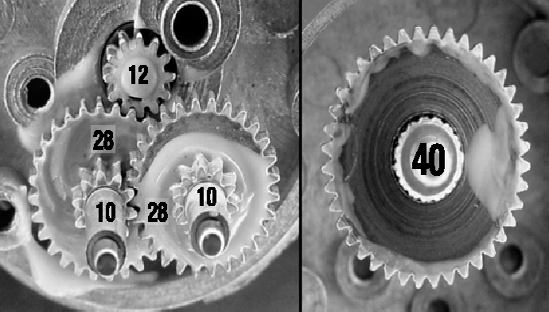
The gear attached to the motor shaft has 12 teeth and it meshes with a larger gear that has 28 teeth. That is attached to a gear that has 10 teeth, which meshes with a larger gear that has 28 teeth. That is attached to a gear that has 10 teeth, which meshes with the final output gear (right side of picture) that has 40 teeth.
The gear ratios of each stage are therefore:
The absolute gear ratio would be described as 31360:1200, even though there really aren't that many actual teeth. That fraction could be reduced to 392:15.
The simplified gear ratio is calculated as follows:
The simplified gear ratio would be described as 26:1. The datasheet claims the gearhead is 30:1, which (according to my calculations) is not really the case.
All of the gears meshing together and pushing on each other involves a lot of friction. As such, gearboxes are usually from 40% to 90% efficient.
The lack of complete efficiency means that gearboxes aren't able to convert all of the reduced speed into torque. You learned earlier that a gearbox with 2:1 gear ratio converts a 4000-RPM motor to 2000 RPM, with 2 times the torque. However, if the gearbox is only 90% efficient, the torque is closer to 1.8 times.
That being said, gearhead motors convert motor speed more effectively than lowering voltage, with the additional benefit of a lot of increased torque.
Some disadvantages of gearboxes are:
increased overall noise
increased overall mass
increased overall length
increased no-load current
None of those factors should dissuade you from the overriding advantages of gearhead motors.
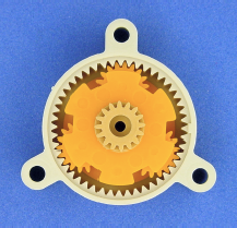
There are actually two major types of gearhead motors. Spur gearboxes are the most common, but planetary gearboxes are also available. Planetary gearboxes contain the same smaller spur gears, except now the smaller gears rotate within the insides of the larger gears (see Figure 17-28).
Stacking layers of planetary gears builds a full gearbox (see Figure 17-29). Just like a spur gearbox, the planetary gearbox is then attached to the top of a plain DC motor. A planetary gearhead motor remains as simple to control as a plain DC motor.
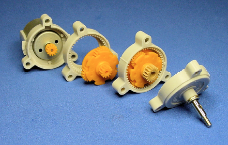
Because multiple smaller gears work in parallel for each larger gear, the planetary gearbox can operate at higher torque that would otherwise damage the solitary smaller gear in a spur gearbox. Alas, the increased maximum torque limit comes with reduced efficiency due to friction.
The output shaft comes out of the center of a planetary gearhead, rather than set off-center like most spur gearheads. Sometimes this is desirable, sometimes not, depending on where you want to place the wheels on your robot. A centered shaft on a gearhead motor usually indicates a planetary gearbox.
The same criteria that apply to selecting a plain DC motor also apply to selecting a gearhead DC motor. Check out the voltage, dimensions, weight, and final RPM.
For heavy-duty torque applications, look for planetary gearboxes with metal gears and metal gearbox frames. However, plastic gears are preferable for lower-torque, quick-action applications, with significantly lighter weight.
Examine the gearbox to see that the output shaft is located at the angle and placement desired. Some gearboxes have unusual shapes, such as rectangles, which add to the overall height of the motor.
Depending on your robot's needs, look for the word "reversible." Most gearheads are designed to allow the motor to continue to operate forward and reverse. However, some gearboxes only allow forward rotation. Non-reversing gearheads are acceptable if you want the robot's wheels to refuse to be pushed backwards.
Hopefully you've now been exposed to enough information about DC brush and gearhead motors to get a sense for their characteristics. There are other varieties of motors common to robotics, such as stepper and servo motors. Although useful in their own ways, they weren't covered in this text simply because they aren't necessary for the robot featured in this book.
In the next chapter, you'll complete your primary education on DC motors by actually attaching them to the line-following circuit.