
The components on Sandwich's circuit board are permanently soldered together. You'll learn about that later. But what do you do if you want to make a quick connection for a simple experiment? No, don't use electrical tape. It's too loose and sticky!
This chapter covers a simple method for making a few temporary connections. It also describes a multimeter test that you can perform to check if an electrical connection has been made.
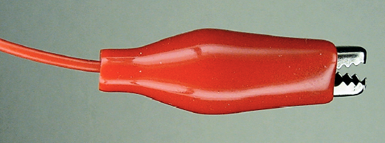
Alligator clips have spring-closing "mouths" that grip parts (see Figure 8-1). Squeezing the center of the clip causes the mouth to open and release whatever it's holding. When you let go of the clip, the mouth closes and can hold onto things.
Alligator clips are friendly. They have a lighthearted name and you can pinch their mouths open and shut like they are eating or saying hello.
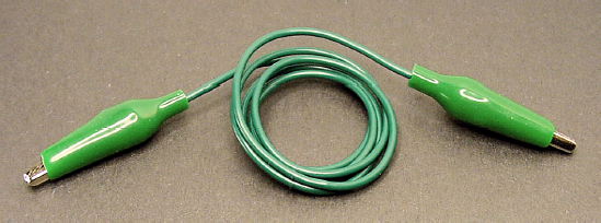
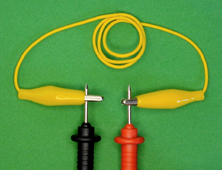
A pair of clips attached by a wire is called a jumper lead or clip test jumper (see Figure 8-2). The wire itself is usually flexible copper surrounded by an insulating colored plastic casing. Now you've got something that can grip a part on both ends and connect them with a wire.
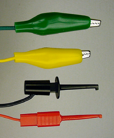
Clips are available in many sizes and colors (see Figure 8-3). Beyond the "alligator" style, there's the mini IC hook, which is smaller and tends to hold onto wires a little better (see Figure 8-4). For these reasons, you'll probably use hooks more often than alligator clips.
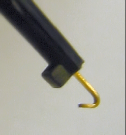
Sometimes the end of a hook bends flat during use. It becomes more like a letter 'L' than a letter 'J.' It's not supposed to be that way. Bend it back. When the hook retracts, it should fit into the hole in the end notch.
Purchase at least five medium alligator and five mini IC hook jumper leads (see Table 8-1). They are available in a variety of colors. Try to obtain red, black, and at least one other color.
Table 8.1. Alligator and Hook Jumper Leads
Supplier | Part Number | Price | Description |
|---|---|---|---|
All Electronics | MTC-5 | $6.50 | (5) Black, red, green, yellow, and white long IC hook |
All Electronics | MTL-10 | $2.95 | (10) Two sets of five colors alligator |
Jameco | 10444 | $4.49 | (10) Two sets of five colors alligator |
Jameco | 135299 | $10.95 | (5) Black, red, green, yellow, and blue mini IC hook |
Mouser | 548-285 | $6.06 | (10) Two sets of five colors alligator |
SparkFun | CAB-00501 | $8.95 | (5) Black, red, green, yellow, and blue mini IC hook |
You're now going to learn how your particular multimeter displays an electrical connection or lack of connection. Then, you'll make a test connection with an alligator jumper lead.
As always, connect the black test lead to the COM terminal of the multimeter.
Connect the red test lead to the Ω or ohm terminal of the multimeter. Most likely the test leads will be in the same places they were when you were testing the voltage of the 9 V battery.
If your multimeter has a continuity feature, turn the dial to that (see Figure 8-5). A continuity test checks to see if a continuous (unbroken) connection exists between the two probe tips. A continuity setting is nice because it usually beeps when a connection is complete, so you don't need to look at the display.
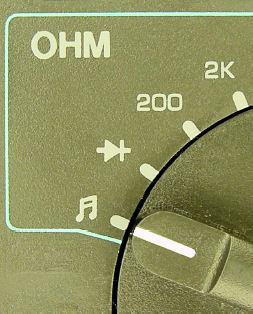
(alternate) If your multimeter doesn't have a continuity feature, turn the dial to the lowest ohm range (see Figure 8-6). This measures resistance. A short wire like the jumper lead should have almost no resistance to electricity flowing through it.

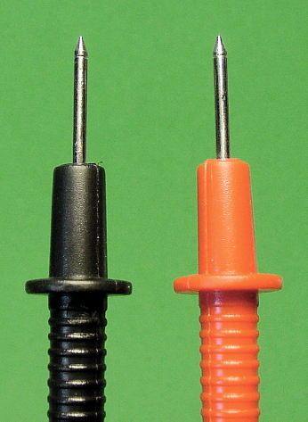
Do not touch the metal tips of the probes to anything at this point (see Figure 8-7). If the meter isn't already turned on, press the power-on button.
A meter with a continuity feature should now display open and should not be beeping. Some meters display "0L mV" instead of the word "open" (see Figure 8-8). Check your meter manual.
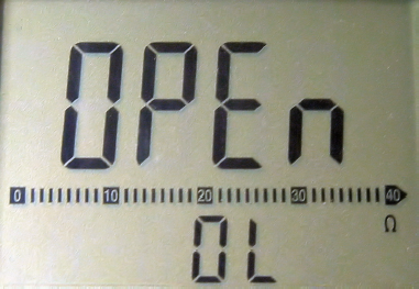
If you don't have a continuity feature, the meter should display 0L or ∞ (infinity) or some very large number in the megohm (M) range.
Since the probe tips aren't touching each other, this connection is "open."
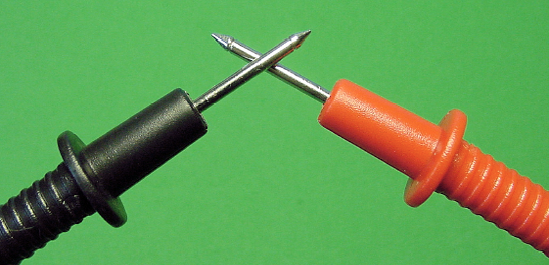
Touch the probe tips together (see Figure 8-9).
A meter with continuity should now display short (see Figure 8-10) and should beep annoyingly. Some meters display "0 mV" instead of the word "short." Check your meter manual.
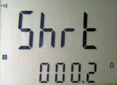
If you don't have a continuity feature, the meter should display zero Ω (ohms) or a very small number.
Ever heard of a "short-circuit?" Well, this one is pretty short. The electricity from the meter goes out of one probe and then directly into the other!
Experiment with the ohm ranges and the continuity setting of your meter. You want to get a good sense for what the meter displays when there is a connection and what it displays when there isn't a connection.
Instead of touching the multimeter probe tips together directly, connect them with an alligator jumper lead (see Figure 8-11). Using a single jumper, attach one alligator clip to the tip of the black probe and the other alligator clip to the tip of the red probe.
You should get the same value displayed on your meter whether you touch the probe tips together directly or whether you connect them with a jumper. The alligator clips and wire are just as good at allowing electricity to flow through them as touching the probes together directly.
During use, alligator clips may become loose or grimy and fail to make a solid connection. The wire between the clips may rip and detach. In those cases, if the jumper lead no longer conducts a continuous connection, you can test for it on your multimeter. A broken connection will read "open" or some ohm value greater than touching the probe tips together.
Think of the wire in the alligator jumper lead as electrical pipe. Electricity flows through the copper wire (or any metal) like water flowing through a pipe. Unlike water pipes, if you disconnect one end of the wire, the electricity doesn't spill all over.
The continuity mode (and also the ohm mode) of a multimeter has a very beneficial use in robotics. It can detect if an unintentional electrical connection exists between various robot body parts and circuits. Although you won't perform these steps now, here are some example steps you might take to test a robot.
Turn the robot's power off. Remove all of the batteries, if possible.
Connect the black test probe of the multimeter to one piece of the robot. If you prefer, you can use an alligator clip to connect the probe tip to the piece being tested. Doing so is a lot easier than holding the black test probe in place. Also, a hook clip may be able to reach spots that would be awkward for a test probe.
Touch the red test probe tip to each metal part throughout the robot, as thoroughly as desired.
If an electrical connection exists between the part connected to the black test probe and the part being touched by the red test probe, the meter will beep (or display "short" or a low ohm value or whatever). It doesn't matter how long or how complicated the connection is. If there's an electrical connection between the parts, the multimeter can detect it.
One of my line-following robots, Sweet, uses a metal candy container for a body. After drilling holes for the sensors and screws (see Figure 8-12), I didn't consider that cutting away the paint coating had exposed the metal in the container to the robot's circuits. When I proudly powered on the robot, the circuits went crazy. Fortunately, I only lost a $15 chip that day.
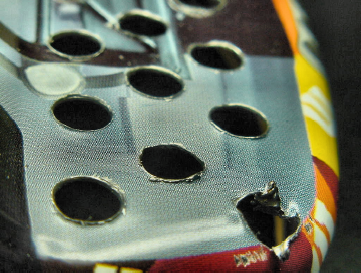
I should have probed the robot a bit with the continuity mode of my multimeter before powering up. By quickly checking the motors, each circuit board, major screws, battery connections, and body, I would have noticed that direct electrical connections had mistakenly occurred between metal parts of the circuit board and metal parts of the robot's container.