A coupler connects two things together. This chapter consists of step-by-step instructions for making a coupler that, in this case, connects the selected gearhead motor's shaft to a LEGO cross axle. The general nature of this coupler is applicable even if you choose a different motor or a different type of wheel.
A coupler is needed because the shaft of the chosen motor is neither the correct shape nor the correct size to accept a LEGO wheel. Even if glue or solder could adhere them together, the robot would probably need to be disassembled or experimentally modified at some point. This would rule out permanent adhesion of the wheels to the motors. The coupler presented in this chapter makes it easy to remove or change wheels at any time.
The line-following robot has two wheels. It needs one coupler for each wheel. Therefore, the robot needs two couplers in total.
These instructions require some light machining with a handheld rotary tool. Most beginners are uncomfortable with machining or metal-working tools. Initially, so was I!
Yet, one of the most fascinating and enjoyable aspects of robotics is creating your own custom body parts. I highly encourage you to at least attempt the relatively simple coupler project in this chapter. It may open your heart to the human-ingrained discipline of physically working with tools.
Buying ready-made parts instead of making a coupler, you can purchase a motor and wheel that are designed to fit together. For example, Chapter 18 suggests the Solarbotics "#GMPW Deal" motor and wheel combination.
If you prefer the Hsiang Neng motors, ServoCity.com sells several different types of ready-made mounting hubs and matching wheels (see Figure 20-1). The motor has a 4 mm shaft. Therefore, buy either a pair of the 4 mm Bore Set Screw Hubs (3470H for $4.95 each) or a pair of the 4 mm Bore Clamping Hubs (3120CH for $7.95 each). The clamping hub is a superior design that holds onto the motor shaft more securely and does not mar the shaft, but it is more expensive.
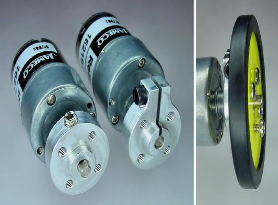
Figure 20.1. The set-screw hub (first motor) and clamping hub (second motor) connect the motor shaft to a ready-made wheel (right)
Matching wheels screw onto the hubs. The wheels are available in a variety of sizes and colors. The two-inch diameter acrylic wheels (#2.00ACR for $3.99) and two-inch diameter foam wheels (#2.00TMD for $16.95) are the correct size for Sandwich. The wheels come in pairs, so don't make the mistake that I did by buying two of them (because you'll end up receiving four wheels).
If you have access to a lathe or a milling machine, you may want to consider an alternative to the instructions in this chapter. In fact, a lathe is the perfect machine to produce the highest-precision LEGO couplers. Instructions are posted at http://www.robotroom.com/LatheCoupler.html.
For readers with a milling machine, Chapters 3 and 4 of Intermediate Robot Building by David Cook (Apress, 2010) provide complete instructions.
At this point, let's assume you've decided to make the LEGO couplers using the instructions in this chapter. The first step is to acquire the raw material.
The coupler consists of a metal tube. One end of the tube has the appropriate inner diameter to accept a standard LEGO cross axle. The other end of the tube has the appropriate inner diameter to accept the selected motor's shaft. The LEGO axle is permanently glued to the coupler, but the motor shaft is held in place by a screw to allow for disconnection.
You can make the couplers out of either brass or aluminum (see Figure 20-2). Brass is three times heavier, about 6 grams for each coupler. Brass is stronger than aluminum, and thus is more likely to retain its shape during metal-working. Most importantly, brass is the easiest to machine. For this reason, I recommend working with brass for your first attempt at making the couplers.
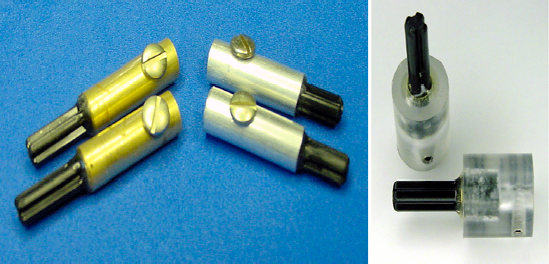
Figure 20.2. Two brass couplers (left) and two aluminum couplers (middle) made with tubing. Two plastic couplers (right) made on a lathe or milling machine out of solid rod.
Aluminum's light weight is a definite advantage for competition robots. Even though it is a softer metal, it is unlikely to break, as the forces exerted on it are trivial on small robot sizes.
Both brass and aluminum tubing are available in display cases at most hardware stores (see Figure 20-3). For this project, you'll need a total of four tubes; one each of diameters 3/16 inch, 7/32 inch, 1/4 inch, and 9/32 inch.
The tube walls must be 0.014-inch thick. "Wall size" is the thickness of the metal.
K&S Engineering manufactures the specific tubing on my couplers, stock numbers #129, #130, #131, and #132. The tubes average around $2.00 each. You can purchase similar tubing online at McMaster-Carr, Online Metals, or MSC Industrial Supply.
One pair of couplers requires only 5 cm of length, but the tubes come in lengths of 12 inches. Plenty remains left over for other robot projects or additional couplers.
If you don't have access to these diameters of tubing, you'll see how the sizes were determined in a moment. That way you can choose appropriate tubing based on what is available to you.
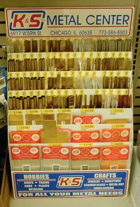
Figure 20.3. Hardware store display case of brass, aluminum, and copper in the shape of tubes, angles, channels, strips, and sheets
With the diameter and wall thickness specified, each tube fits neatly inside the next larger size (see Figure 20-4). This is called telescoping tubing. At the store, try sliding one tube into the other to make sure they fit snugly.
A LEGO cross axle must fit into one side of the coupler. By inserting a LEGO axle into various tubes, the closest match is found to be a 7/32-inch diameter tube (see Figure 20-5).
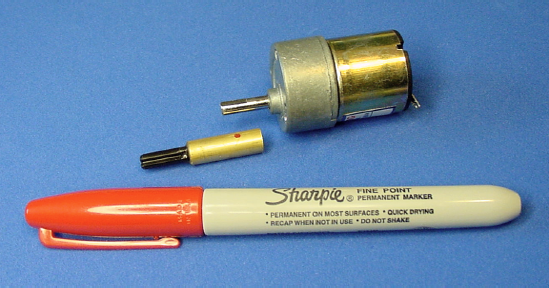
The shaft of the selected motor must fit into the other side of the coupler. By inserting the motor shaft into various tubes, the closest match is found to be a 3/16-inch diameter tube (see Figure 20-6).
Because the tube diameters differ on each end of the coupler, a single metal tube can't connect the axle and the shaft. Luckily, a 3/16-inch diameter tube with 0.014 inch walls fits snuggly within a 7/32-inch diameter tube with 0.014 inch walls. The 3/16-inch diameter tube is cut to half the total length of the coupler and inserted into the 7/32-inch diameter tube. This way, one half fits the motor shaft and the other half fits the LEGO axle.
This explains how the wall size and two of the four tube sizes were determined. The other two tubes have larger diameters. Those tubes slide over the smaller tubes for added strength and to provide enough thickness to add a screw hole.
The tubing comes in lengths longer than needed for the coupler. The desired length of the individual tubes needs to be determined and then cut accordingly.
The motor shaft sticks out 15 mm. The motor-shaft half of the coupler should be a bit shorter, say 13 mm, to avoid rubbing against the gearbox cover as the shaft rotates.
Measure two 14 mm lengths on the 3/16-inch diameter tubing. Mark the two locations to cut with a fine-point felt-tip permanent marker (see Figure 20-7). Why 14 mm? Didn't we just decide we wanted a 13 mm length? Yes, but about a millimeter is going to be lost during cutting and sanding, so a 14 mm mark results in a 13 mm cut and finished tube.
Measure two 23 mm lengths on the three larger-diameter tubes. These tubes will span the entire length of the coupler, about 22 mm, after cutting and finishing. Cut the tubes longer if desired, but a wider robot will result.
There are a number of tools that can cut tubes. A fine-toothed hacksaw works, although the thin walls of the tubes usually bend or deform. You can insert a suitably sized wooden dowel within the tubing during cutting to reduce warping, but there are tools that are superior to a hacksaw for cutting small tubes.
A tube cutter is a tool designed specifically for cutting tubes (see Figure 20-9). A tube is placed between a rotating blade and two rotating rollers. Twisting a knob pushes the two rollers against the tube, forcing the tube into the blade. By rolling the tube and twisting the knob over and over, the blade eventually cuts through the entire circumference of the tube.
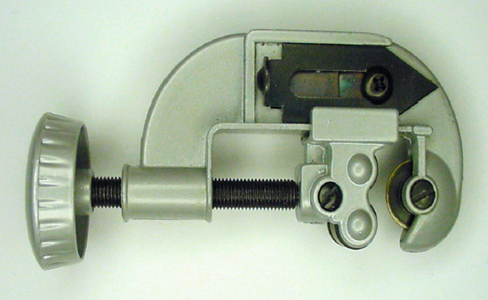
Although this tool cuts very straight, the ends of soft tubing curl in slightly after being cut. With this reduced diameter on the ends, the tubes no longer fit inside of each other. You can sand the curled ends down or core them out, but it isn't worth all the effort.
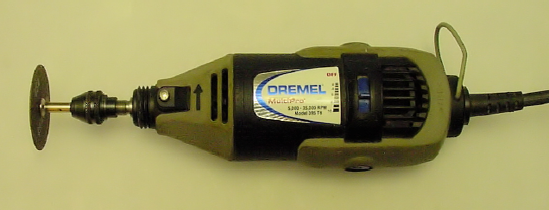
A variable-speed rotary tool is like an extremely fast power drill (see Figure 20-9). But instead of only making holes, you can add various discs and attachments to sand, carve, route, and cut.
Warning
Always wear a dust mask and safety glasses when operating a rotary tool.
Variable-speed rotary tools are available at most hardware stores. The tool runs from $35 up to $200 depending on the features and included accessories. Dremel manufactures the most popular brand. There's nothing wrong with starting with the least-expensive model, although a mid-price kit is a better investment.
In robotics, a variable-speed rotary tool is as irreplaceable for bodywork as a multimeter is for electronics. It is worth obtaining and practicing with this valuable tool.
A vise consists of a pair of heavy metal blocks, called jaws, connected via a screw (see Figure 20-10). Turning the screw handle causes the jaws to come together, clamping the material in between. This firmly holds the piece on which you're working.
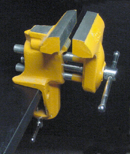
A small bench vise is fairly inexpensive and is a necessary tool in robotics.
To cut the tubing with a rotary tool, first place the tubing in a vise (see Figure 20-11). Gently tighten the vise, but make sure it's not too loose or the tubing will slip during cutting, and not too tight or the tubing will be crushed.
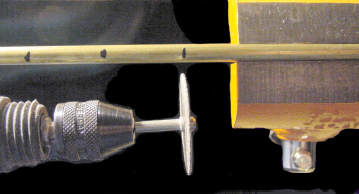
Figure 20.11. Rotary tool with cut-off wheel (lower left) about to cut through tubing at marked locations. The tubing is held firmly within a vise (right)
Insert a heavy-duty or fiberglass-reinforced cut-off wheel attachment into the rotary tool. Bring the rotary tool to the lower range of its speed and lightly maneuver the blade through the tubing at the marked location.
The picture in Figure 20-11 was taken for illustrative purposes. You actually want to start cutting at the first mark on the tube, with the remainder of the tube firmly in the vise. If the tube is hanging way out of the vise, it's going to vibrate a lot, marring the cut. If a middle mark is cut before the first mark, half of the tubing is going to fall on the floor.
The bulbous front of most rotary tools sometimes gets in the way of cutting straight across the tubing. To make things worse, the cut-off wheel shaves down over time, becoming smaller with use. A fresh cut-off wheel helps, as does a flexible shaft extension. However, don't be overly concerned with the angle of the cut, as it can be corrected with sanding and, in any case, it doesn't cause the coupler to wobble.
Depending on the method chosen for cutting, freshly cut tubing commonly contains hanging metal particles called burrs. Rubbing the cut face in a circular motion against sandpaper cleans the rough ends of the tubing (see Figure 20-12). You can use a fine single-cut or Swiss-pattern file, but sandpaper seems gentler.
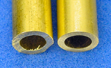
Figure 20.12. Freshly cut tubing showing scratches and burrs (left). Finished tubing sanded flat and clean (right).
Sandpaper is usually available in assorted packs of different grades of coarseness. Choose a variety pack labeled for use on metal, like aluminum-oxide sandpaper. It should contain sheets from medium (100 grit) through extra fine (225 grit). For a beautiful finish, also pick up some sheets of super fine (400 grit) silicon-carbide sandpaper, or even finer.
Warning
Always wear a dust mask and safety glasses when sanding.
Lower grit numbers remove more material more quickly, but scratch the workpiece. Start with coarser sandpaper (100 grit) to straighten out the cut or remove large chunks. Then, work the piece through finer and finer sandpaper (225 grit) until you achieve the desired smoothness. Other than aesthetics, there's no reason to put a mirror finish (even finer than 400 grit) on the tubing. But, at the very least, remove all burrs and sharp edges.
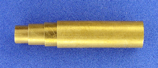
To make one coupler, you should now have three 22 mm long tubes of diameters 7/32 inch, 1/4 inch, and 9/32 inch. You should also have a 13 mm long tube of 3/16-inch diameter.
Combine the three 22 mm long tubes by pushing the tubes into each other to form one thicker 22 mm long tube (see far left of Figure 20-13). If any of the tubes don't slide in easily, carefully sand the blocked tube or replace any damaged tubes. Don't worry if the tube lengths vary a little bit, and are not completely even. You can either ignore it or sand the end down as a group.

Figure 20.13. Left: Three 22 mm tubes inserted together (left side of left panel) placed beside a 13 mm tube (right side of left panel). Right: 13 mm tube partially inserted to test the fit
Insert the 13 mm long tube into one end of the 22 mm long combined tube. Again, test for a smooth fit. When satisfied, separate the tubes again (the end of a small screwdriver or the remaining stock of tubing helps push the inner tubes back out).
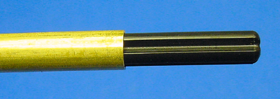
A LEGO cross axle is long thin black beam that looks like a plus sign (+) or the letter "X" when viewed from the end. LEGO axles are designed to insert into the hubs of wheels, gears, and other LEGO parts. Although the connection is achieved only by friction, the fit is firm and usually doesn't shift or separate during use.
LEGO pieces are commonly measured in comparison to the number of studs on top of a standard LEGO brick. For example, the cross axles in Figure 20-14 are 4, 5, and 6 LEGO units in length. (That translates to 31.8 mm, 39.7 mm, 47.6 mm.) LEGO cross axles are available in LEGO unit lengths of 2, 3, 4, 5, 6, 8, 10, and 12.
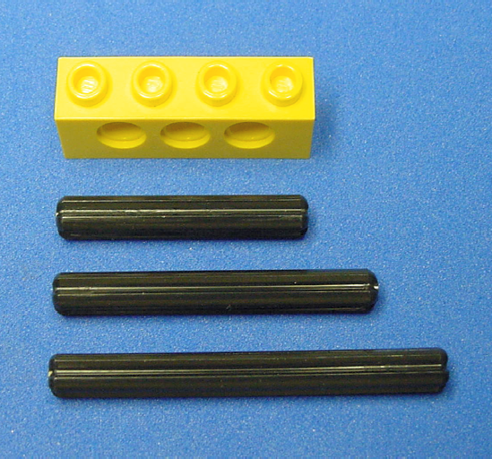
Figure 20.14. Three example lengths of LEGO cross axles beside a 4 LEGO unit brick (top) for comparison purposes
The minimum length of axle that should be installed in a coupler is about 2.5 LEGO units long (a 5 LEGO unit axle cut in half). Anything less than that either isn't long enough to connect to a LEGO piece or has too little of the axle supported within the coupler's metal tubing. Properly supported, even a 12 LEGO unit axle can be attached to a coupler.
Sandwich's coupler has a 3 LEGO unit cross axle. Actually, the coupler was made from a 6 LEGO unit cross axle cut in half because that size of axle is a more common part. If you decide to cut an axle in half (use the rotary tool cut-off wheel accessory), be sure to place the cut end into the coupler and leave the official tapered end sticking out. The taper makes it easier to slide on a wheel.
Axles longer than 3 or 4 LEGO units tend to stick out farther than necessary for a wheel. That length is usually reserved for axles intended to reach wheels or gears in a frame (see Figure 20-15). Placing a wheel at the end of a long unsupported axle runs the risk of bowing or snapping the plastic axle.

Glue adheres best to parts that are free of dust and oil. Be sure to clean the individual tubes and the LEGO cross axle before gluing. An ultrasonic cleaner works well, but hand cleaning in soap and water is perfectly acceptable. Let the parts dry completely before gluing.
Until recently, I always skipped the step in directions that said, "Clean and dry parts completely." Then, I ran across a LEGO cross axle that would not glue.
LEGO axles are made of polypropylene thermoplastic (the same as Sandwich's body container). Both polypropylene and polyethylene are beloved for consumer containers due to their incredible resistance to chemicals. That same property makes those plastics almost impossible to glue. After all, what substance do they make glue containers out of?
Polypropylene has an inherently low surface energy. With oil, grime, and dirt coating the surface, there are even fewer available binding locations for the glue. By thoroughly cleaning the axle of all contaminants, the glue has additional opportunities to grab hold. For best results, immerse the axle in isopropyl alcohol and wipe with a cotton ball.
Some special glue kits on the market contain a separate bottle of hexane, which acts as an accelerant. Cyanoacrylate adhesive (super glue) dries extremely quickly on hexane-treated surfaces, thus locking the glue in sharp shapes that grab at the surface, rather than allowing the glue time to pull away like water beads on a freshly waxed car. Hexane is a last resort—a clean surface usually does the trick.
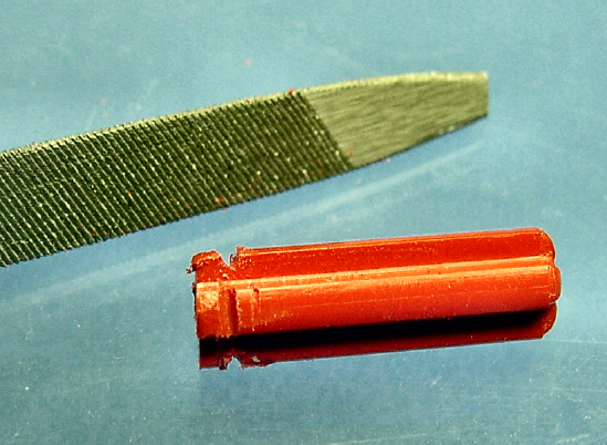
Before cleaning the axle, consider using a file to cut notches into the end of the axle (see Figure 20-16). The glue will fill these voids. When hardened, the glue in the notches will prevent the axle from being pulled out, even if the glue didn't adhere to the axle surface.
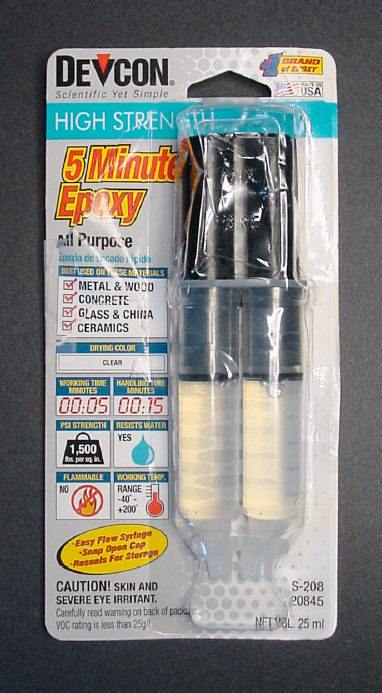
Two-part epoxy resin works well for gluing together the entire coupler. Epoxies are thick, strong, and appropriate for filling voids. There are a variety of epoxies available from hardware stores. Try to find one that dries clear (see Figure 20-17).
Warning
During gluing, wear vinyl or nitrile (not latex) gloves. Enough skin exposure to epoxy resin leads to an allergic reaction.
Follow the directions on the package. Mix the epoxy on a scrap piece of paper. Spread a thin coat on the outside of a cut tube and insert it into a larger tube. As each tube is inserted, twist the tube to spread the epoxy evenly throughout.
When the coupler tubing is completely assembled, twirl the end of the LEGO axle in the epoxy on the scrap piece of paper. Get a big glob of epoxy on the end and make sure it fills the notches in the axle. As the axle is inserted into the tubing, twist and pump the axle to distribute the epoxy throughout the inside of the tubing. The idea here is to have the epoxy fill all the space between the "X" shape of the axle and the "O" shape of the tubing.
Give the epoxy plenty of time to dry. The package on the epoxy I use reads, "full strength in 1 hour."
After drying, sand or chip off extra epoxy as desired. Notice how easily the epoxy chips off the plastic LEGO axle? Don't worry! If the axle was very clean and you made notches with a file, the axle should hold quite strongly in the coupler. If the axle falls out for some reason, a nice reverse "X" of epoxy remains in the coupler. Try some hexane and cyanoacrylate adhesive to adhere the axle back in place within the epoxy reverse "X".
Fortunately, the axle doesn't get tugged on very much as it gets rotated. Most of the motor force transmits to the axle through the reversed epoxy "X". As such, the epoxy's shape and adherence to the tubing are more important than adherence to the axle.
If you applied plenty of epoxy, it's likely that some got forced down into the motor shaft's side of the coupler. Drill out the invading fragments with a rotary tool and a 1/8-inch drill bit. As long as the chips come out white, you haven't hit the black plastic LEGO axle yet. The axle is much harder and resists drilling. If the drill feels like it has bottomed out or black chips start coming out, you've drilled deeply enough. Some epoxy sticking to some of the sides of the tube may still need attention from the drill.
The coupler is almost complete. Something needs to be added to hold the coupler on the motor shaft, yet still allow removal.
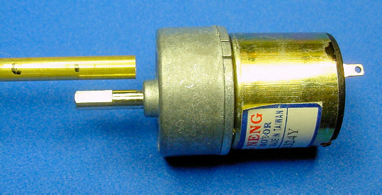
A setscrew is a small screw that applies pressure against the flat portion of the motor shaft. Not only does the screw prevent the shaft from sliding out of the coupler, but it also forms a "D" shape within the coupler. The flat side of the "D" shape gives the flat portion of the motor shaft something to push against, so that the shaft spins the coupler rather than the shaft just spinning within the coupler.
Hold the coupler beside the motor shaft to determine a good location for the hole in the coupler. Aim for the end of the flat portion of the shaft that's nearest the motor. That tends to be around 6 mm or so from the end of the coupler. Mark the spot with a fine-point felt-tip permanent marker (see Figure 20-18).
A drill press is a device that holds a drill firmly and completely perpendicular to the work piece (see Figure 20-19). A lever on the side of the press lowers the drill straight down. Notches on the lever indicate the depth drilled, for precise control.
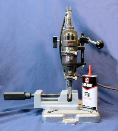
Figure 20.19. Dremel rotary tool installed on a Dremel drill press. Optional oil and drill-press vise also pictured.
With the drill turned off, you can position the workpiece and lower the lever to show exactly where the hole would be drilled. Thus, a drill press insures that a hole will be drilled straight, in the exact location, and to the exact depth intended.
Maybe I'm sounding like a broken record, but this is a third tool (rotary tool and vise being the other tools) that I couldn't build decent robots without. The Dremel drill press or Dremel Rotary Tool Work Station is available at hardware stores and Amazon.com.
The Dremel drill press comes with instructions for making clamps to hold the piece being worked on. A drill-press vise is a superior solution for small items. The Wolfcraft vise has a V groove in the jaw to hold round items, which is perfect for the coupler (see Figure 20-20). The vise is available from Micro-Mark, item #82546, for $26.50.

Simply drill in the location marked earlier. Use a #43 drill bit. If you don't have that size, you can substitute a 5/64-inch diameter drill bit for shallow holes. But, for deeper holes or stronger materials (like steel), you really must use a #43.
Drill all the way through the tube wall, but not through the tube wall on the other side.
Aluminum drills easily with a Dremel. Brass is slightly more difficult and may require a drop of oil to aid cutting and chip removal. In fact, after drilling the start of a straight hole in brass using the rotary tool, I switch to a power drill to finish the job.
A T-handle tap wrench is the tool that makes the internal threads in a hole for a screw or a bolt. A 4-40 taper tap (size 4, with 40 threads per inch) is required to finish the setscrew hole in the coupler. Tap and die sets are available at most hardware stores. Make sure the set includes the standard 4-40 taper thread tap or, if necessary, purchase it separately.
Carefully insert the taper tap into the start of the hole that was already drilled (see Figure 20-21). Try to keep the tap as straight and square as possible to the hole. By slowly turning, the taper tap begins to dig into the metal on the sides of the drilled hole. Be firm, but don't force it. It twists in, not pushes.

Figure 20.21. By turning a T-handle tap wrench, the taper tap starts cutting internal threads in the sides of the hole in the coupler
Every turn and a half, turn backwards a half turn or so to work excess metal out of the hole. If turning becomes a struggle, rotate the tap completely out and remove the chips from the tap and hole with a piece of cloth (not your fingers). A little oil or cutting fluid helps, too.
From a hardware store, purchase some #4–40, 1/8-inch long panhead machine screws (see Figure 20-22). Panhead refers to the shape at the top of the screw. Panhead screws are flat and wide, keeping them near the shaft while being easy to grasp by hand. Choose either slotted or Philips screw head styles.
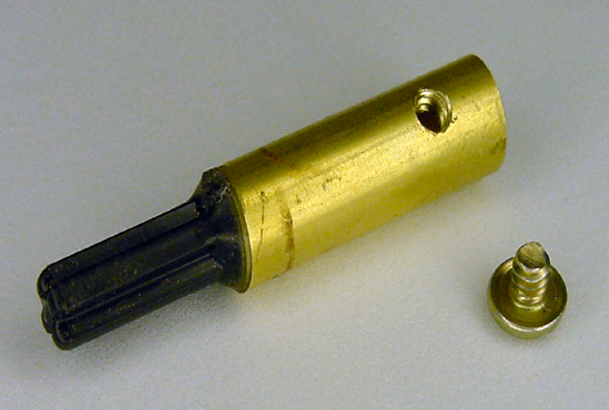
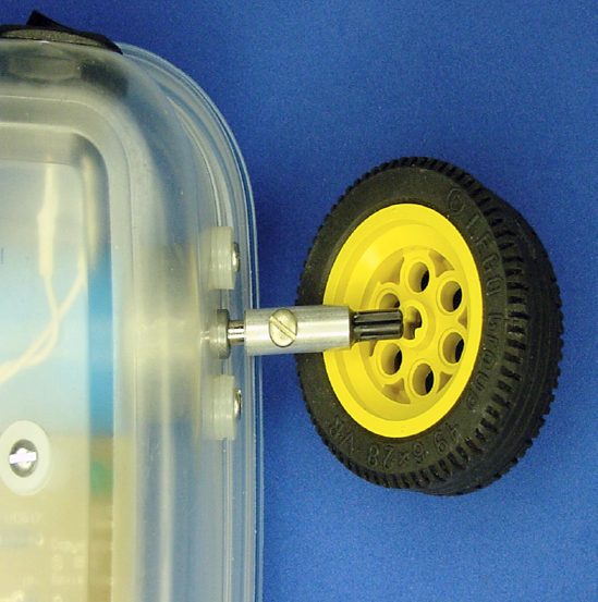
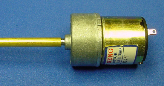
The setscrew makes it simple and quick to install and remove the coupler from the robot. Equally beneficial, the LEGO cross axle allows for a variety of LEGO wheels to be slid on (see Figure 20-23). The LEGO axle accepts LEGO gears and other parts as well, so you can use the coupler to motorize more than just wheels.
You can modify this coupler design for other types of wheels and different-sized motor shafts. Using telescoping tubing ensures that the wheel hub and motor shaft are perfectly centered, eliminating any up and down play or wobble during operation.
Because of all the tools and components required to make the couplers, I usually build more than I need at a time. With half a dozen extra couplers floating around the home laboratory, you can build robots quickly when inspiration strikes.