You've gained an understanding of the items and methods needed to get a good start at robot building. You've read schematics and hopefully experienced prototyping, soldering, and tweaking. Maybe you've even built your first robot.
Where do you go from here?
It seems that there's a never-ending stream of new parts, tricks, and technologies in the world of robotics. That's half the allure. Besides the everyday challenges that remain to be solved by robots, there are also plenty of organized contests. This chapter highlights some of the components, challenges, and contests that may interest you as next steps.
The line-following robot contains the primary electrical components encountered in almost all robot designs: batteries, resistors, diodes, transistors, IC chips, LEDs, potentiometers, and switches. In fact, you'd be hard pressed to build a decent robot without these pieces.
As this book is aimed at novice backyard scientists, a few noteworthy parts were excluded to reduce the complexity of the robot presented. Before closing, I decided to examine all of my robots (both real and imagined) to make a list of useful components that otherwise would have gone unmentioned.
At one time, logic chips ruled the circuit board. Like the comparator used in the line-following robot, each logic chip performs a very specific function. For example, an AND logic chip turns on the third pin when the first pin is on and the second pin is on. An OR logic chip turns on the third pin when the first pin is on or the second pin is on.
A portion of the numbers printed on the chip indicates the industry-standardized function. For example, a 7404 chip (see Figure 26-1) is an inverter. When the input pin is on, the output pin turns off. When the input pin is off, the output pin turns on. This chip is useful if you need an "off" condition to turn something on.
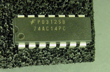
Like a six-pack of beer, simpler logic chips contain multiple copies of the same function in a single package. For the 7404 inverter chip, it has a six-pack of inverters: 6 inputs + 6 outputs + 2 power pins = 14 pins.
As microcontrollers and programmable logic array chips became less expensive and more powerful, most of the more complex functions (counter chips, math chips, single bits of memory, and so on) became obsolete. Besides the obvious economic incentive, you can program complex relationships inside of a single microcontroller chip instead of wiring together a board full of logic chips.
Some logic chips still have their place in modern electronics. Inverters, AND, OR, latches, transceivers, de/multiplexers, de/coders, parallel to serial, and serial to parallel chips can do a lot in robots. They're cheap, wonderful for experiments, great for learning digital electronics, and helpful companions to microcontrollers.
Without a doubt, the biggest advancement in robotics is the microcontroller. Microcontrollers contain memory and storage space, just like tiny computers. Programs are written on a PC and then downloaded to the robot usually via a USB cable to a programmer board.
If you're dreaming of building a smart robot one day, the microcontroller is a necessity.
Although there are sets of special-purpose pins on the microcontroller chip, the remaining pins can provide whatever functions you desire. Blinking an LED is as simple as writing a program that says, "turn on pin 4, wait, turn off pin 4, wait, and repeat."
The line-following robot could be greatly improved by replacing the comparator with a microcontroller. For example, each photoresistor could be evaluated individually to perform smooth turns (when the line is slightly off center), hard turns (when the line is under a far sensor), or to go straight ahead (when all sensors have approximately the same value).
With a microcontroller, motors can be enabled individually or at the same time. With sensors watching the wheels, the microcontroller could insert brief pauses in motor power to slow down when the battery is fresh or a turn is sharp.
With a set of switches in the front and sides of the robot, the microcontroller could stop and back up when a switch is pressed by a collision. The capabilities and creative options provided by a microcontroller make it a must-have part in modern robotics.
Microcontrollers are relatively inexpensive, most cost between $1 and $15 each. However, the programming boards are expensive, costing between $99 and $400. But, that's a one-time expense for a particular chip. To further reduce costs, some hobbyists sell simplified programming boards, often built into a cable, for as little as $20.
Another expense is the programming language. Some microcontrollers include a BASIC language, but most ship with assembly language, which is a more powerful but more complicated language. If you come from a computer science background, you'll be pleased to discover C, C++, and some Java compilers are generally available for most microcontrollers for an additional price.
The microcontroller market is very competitive, so most manufacturers provide equally capable products. Usually, the reason someone supports a particular microcontroller is because that's the chip family the person learned first. Once invested, it's very difficult to get a designer to discard their tools and knowledge for a different manufacturer's product line, especially for one that only proves equivalent.
I prefer Atmel 8-bit AVR microcontrollers (see Figure 26-2). My newest robots are based on them. Almost all of the ATmega and ATtiny series are available in hobbyist-friendly DIP packages.
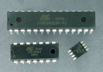
Figure 26.2. Atmel microcontrollers: ATmega328 (top), ATtiny84 (bottom left), and ATtiny85V (bottom right)
Other designers prefer Parallax Propeller (multi-core), and Microchip PIC. Another choice is Arduino, which is an open-source microcontroller platform that is compatible with a wide variety of ready-made and enthusiast-created boards.
The major issue that complicates establishing the brightness of an LED, and other calculations of current, is that the battery voltage declines with use. That factor also makes it difficult to document test point voltages for comparison with acceptable values. Is 6 V okay at test point 1? I don't know, maybe. It depends on the voltage of the battery.
Steady voltage makes for consistent brightness, consistent motor speed, and a single set of calculations. More significantly, steady voltage provides an environment suitable, if not strictly required, for fussier chips or sensitive components.
Like other parts, voltage regulators come in a variety of packages (see Figure 26-3). The most basic regulators take positive power on one pin, negative power on another pin, and output a steady voltage on a third pin. Fancier regulators have additional pins that indicate a low battery or provide a power-suspend feature.
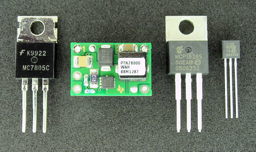
Figure 26.3. Robot-friendly voltage regulators: (left to right) classic 7805, high-efficiency PTN78000 switching-regulator, low-dropout MCP1826, and low-dropout MCP1702 in a compact package.
Many regulated voltage values are available, such as 1.8 V, 2.8 V, 3.3 V, 5 V, 8 V, and 12 V. 5 volts is the most common among hobbyists, as many chips operate at that voltage. To save power, lower voltages are more common with modern commercial products, such as cell phones and handheld devices. Some regulators allow you to specify any voltage within a reasonable range by attaching a pair of resistors.
There are two major types of voltage regulators:
Linear regulators require a battery voltage above the final desired voltage, with the regulator discarding the extra. That's a waste of power, but it works. So, a 9 V battery could be regulated at 5 V for its entire useful life. The voltage regulator wouldn't output 4 V when the battery was at 8 V, it would always output 5 V. The discarded extra voltage is turned into heat.
Switching regulators conserve power by converting voltage using capacitors or inductors. Excess voltage is almost always converted into additional current. Some switching regulators are designed to step-down higher voltages, some step-up lower voltages, and others buck-or-boost (raise or lower) depending on the battery's output. Although not 100% efficient, the best switching regulators approach 90% under ideal conditions. Besides saving power (thus extending battery life), switching regulators don't get as hot as linear regulators.
When selecting a voltage regulator, look for your desired final output voltage, the minimum input voltage, the maximum input voltage, the maximum current allowed, and the typical quiescent current (how much current the regulator uses for itself).
Other beneficial features to look for in a voltage regulator include reversed battery protection, thermal shutdown if overheating, and damage protection if the attached board has a short circuit.
As described earlier, capacitors are power storage devices. Unlike batteries, capacitors don't hold a lot of energy, but they can charge and discharge an almost unlimited number of times. Most capacitors are small, lightweight, and inexpensive.
Almost every robot circuit requires capacitors. The line-following circuit is fairly rudimentary, but probably would require a couple of capacitors if additional chips were added.
Capacitors have a number of vital uses:
Absorbing small power spikes and power dips (reducing electrical noise);.often called a "decoupling" capacitor in this role
Providing large bursts of power on demand, such as when a motor starts up
Maintaining circuit power to a memory module or real-time clock for a short time while a battery is being replaced
Storing regulated voltage
Acting as buckets to increase voltage in a voltage multiplier circuit
Creating an inexpensive oscillator or timer by charging and discharging slowly across a resistor; often called a "timing" capacitor in this role
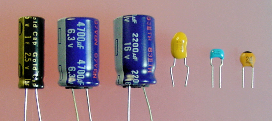
The two most important characteristics of a capacitor are the maximum amount of charge it can hold (expressed in farads, abbreviated F), and the maximum voltage it can handle (expressed in volts, abbreviated V). The maximum voltage is easy to understand; don't use a 6.3 V capacitor to store 9 V.
The amount of charge, F, is a little more difficult to comprehend, but it will be clearer once you see how it is commonly used and its capacitor ratings:
Greater than 10000 μF: used for industrial and military machinery, and solar panel collection. Smaller voltages are used to retain memory or system clocks.
100 μF to 10000 μF: used to provide large bursts of power for motors or other current-hungry components. Upper values used on solar robots.
1 μF to 100 μF: retains a short-term supply of power from a voltage regulator or power supply.
0.1 μF: used to connect to the positive and negative pins of chips to reduce electrical noise.
1 pF to 1 μF: used in moderately accurate timing circuits.
1 pF to 40 pF: vital for high-accuracy crystal-based oscillator circuits, especially those for microcontrollers and microprocessors.
As would be expected, the greater the maximum voltage and the greater the capacity, the larger the physical size of the capacitor. In Figure 26-4, the second and third capacitors are the same physical size. The one on the left has a smaller maximum voltage but greater capacity; the one of the right has a larger maximum voltage but smaller capacity.
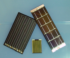
A robot that continues to operate autonomously without regular human intervention seems more alive than a robot that dies when its battery runs down. The ability to independently recharge, either by returning to a power station or via solar panels, is a real milestone in robot design.
A big problem with small solar panels (see Figure 26-5) is that they don't provide nearly enough continuous power for a motorized robot. You can overcome this byhaving the solar panels recharge a battery or capacitor, and also by limiting motor activity to short, daylight trips.
There's a whole class of tiny, simple robots that utilize solar panels instead of batteries. These are called BEAM robots. Because of their limited intelligence and size, they're easy to make. BEAM robots seem to attract artisans as builders, as some BEAM robots are absolutely stunning to behold.
The lack of a battery requires the robot to stand motionless for long periods at a time, charging a capacitor from its solar panel (see Figure 26-6). Then, in a rapid burst, the robot releases the power through its brains and motors, and begins the cycle again.
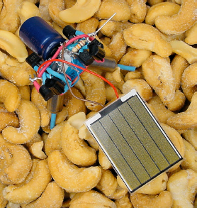
Because they don't have a battery, BEAM robots often lack a power switch. Instead they wander around all day, and sleep at night.
If you're interested in learning more, check out the Solarbotics company web site, http://www.solarbotics.com/.
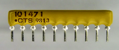
If a robot circuit contains a lot of resistors of the same value, purchasing a part that contains multiple resistors in the same package can save space.
A resistor network, also called a resistor array, consists of many resistors in a single part (see Figure 26-7). Depending on the package, the resistors may be electrically independent of each other, they may be wired so that one end of all of the resistors connects to a single pin, or they may have bizarre arrangements employed for bus termination. Before ordering, be sure to examine the manufacturer's schematic to determine the layout you desire.
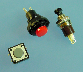
Most pushbuttons are spring-loaded switches. Push down and the switch connects, let go and the switch disconnects. Other than that physical difference, the robot sees switches and pushbuttons identically at an electrical level.
Pushbuttons (see Figure 26-8) find their place on keyboards as well as mode selectors, reset buttons, start buttons (stop! buttons), and control pads.
Pushbuttons can also be used as "soft" power switches on smart devices. Most VCRs, TVs, and stereo equipment work this way. Unlike a real power switch that totally disconnects power, soft-powered devices often contain an internal chip constantly receiving power that watches the pushbutton. When the user pushes the button, the brief continuity causes the chip to enable power (via a relay, transistor, or voltage regulator) to the rest of the circuits. When the user pushes the button again, the chip disconnects power to all of the circuits but its own.
The soft-power button approach is especially valuable to circuits that can be powered remotely, can turn themselves off after a period of disuse, or can turn themselves on at a certain time (like a VCR, handheld PDA, or fancy coffee machine). A soft-power button would be very appropriate for an autonomous robot, so long as the batteries were physically removed for servicing.
Personally, I select pushbuttons on the basis of how good they look or feel to the finger.
A word of warning with pushbuttons and switches: there's a moment during the physical transition between on and off when the switch fluctuates, turning on and off very quickly before settling. If a chip is watching a switch, it's a good idea to use capacitors or some sort of a delay to hide the indeterminate phase, otherwise the robot or device may think the user pressed the button a bunch of times. Switch filtering techniques are called "debouncing" the switch.
You may recall from the comparator chip that DIP stands for dual inline package. Although not guaranteed, DIP usually implies a standard width and pin spacing.
There are groups of tiny switches available in the standard DIP size (see Figure 26-9), making them perfect for breadboards. DIP switches act like normal switches, connecting and disconnecting wires.

Because of their small size, DIP switches are difficult to toggle without a tiny screwdriver. Also, the internal switch wiring is a bit delicate. So, they can't handle really large currents or voltages and they may break if switched too often or too aggressively.
DIP switches are excellent for making your robot configurable. I try to load as much intelligence as possible into the programming of my robots, but sometimes, especially on the day of a competition, a robot likes to play dumb. With configurable DIP switches, you can manually select certain settings or patterns to coach the robot to victory.
Think of DIP switches as the on/off equivalent of trimpots: Sometimes you need to perform a tweak or two on the track under ambient conditions.
To save money, jumpers and shorting blocks often replace DIP switches for the purpose of configuration on mass-produced circuit boards.
A plastic piece, called a "shorting block" (see Figure 26-10), containing a thin strip of metal is placed over a pair of pins on the male header on the circuit board. Thus, the metal strip connects the pins as a switch would.
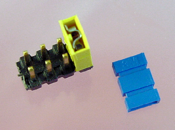
Jumpers and shorting blocks are less expensive than DIP switches, take up less space, can handle a bit more current, and can be cut down to a single pair of pins if desired. In most cases, I prefer DIP switches for configuration, since they don't have parts that can come loose and become lost. However, shorting blocks provide multimeter access to the male header's metal pins, so current flow can be tested.
You can imagine the futility of an upside-down robot spinning its wheels. The first step toward a robot righting itself would be to know it has tipped over (sort of a 12-step program for robots).
Figure 26-11 is a part that I've always been meaning to try out. A metal ball rolls around a bunch of metal pins. Whenever the ball touches two or more pins, they're connected together electrically. That way, a circuit could detect if the robot was upside down or tipping in some direction by checking to see which pins were "switched" together.
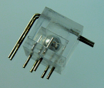
I can't imagine the part will work while the robot is moving, since the ball probably bounces around a lot. But, it might be functional when the robot pauses.
A thermistor is a variable resistor, just like a potentiometer, but one that changes resistance with changes in temperature. For example, a negative temperature coefficient thermistor decreases in resistance when you hold it in your hand or against a light bulb. It increases in resistance when dipped in ice water.
Thermistors are very small and fairly inexpensive (see Figure 26-12). They often sit inconspicuously on circuit boards, within battery packs, or in probes.
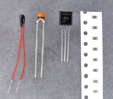
Figure 26.12. Various thermistors for measuring temperature. The first two are plain, the LM34 includes built-in electronics (center right), and the far right side shows a strip of tiny surface-mount thermistors.
A thermistor is as easy to use as a cadmium-sulfide photoresistor. Hook the thermistor up in a series with a standard resistor and test the voltage at the point where they connect. A comparator would work well with a thermistor. In fact, you could replace the photoresistors in the line-following robot with thermistors, and you'd end up with a really lame heat-seeking robot (thermistors change values too slowly and they'd all be measuring nearly the same local air temperature.)
For the best results, a thermistor should be read by a smart part, like a microcontroller. The microcontroller could contain a table of resistances with associated actions (shut down the battery charger at a certain temperature) or the numeric temperature values to display (like degrees Celsius).
Sandwich has no method of detecting a wall, and thus smacks into it. But there are some basic sensors that can provide robots with a crude sense of touch.
The simplest sense of touch is a pushbutton of some form. Appropriate pushbuttons for touch sensing have long lever arms that activate with little force (see top right of Figure 26-13). The pushbutton can electrically disconnect a motor, connect it in reverse, or signal the event to the brains.
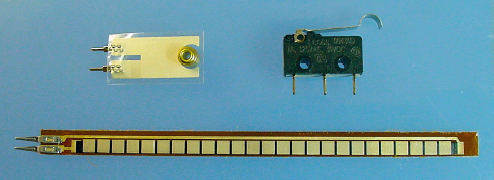
Figure 26.13. Touch sensors: vibration sensor (top left), snap-action level switch (top right), and Jameco #150551 $12.95 flex sensor (bottom)
Flex sensors are variable resistors (see bottom of Figure 26-13). As they bend, they change resistance. You can see this in action on a multimeter in Ω mode. Flex sensors work well with comparators or microcontrollers. Surrounding the robot with a ring made of flex sensors would inform the robot of the slightest warping from any side.
One form of a vibration sensor is a stubby flex sensor with a weight attached (see top left of Figure 26-13). You could put a couple of these inside a robot at different angles and determine the gross direction in which the robot is oriented. Or, knocking the robot on the head could make it say "ouch" or start moving.
A popular technique for detecting the presence of an object is to use an infrared LED to blink a signal and simultaneously check an infrared detector to see if the signal bounces back. If the signal doesn't bounce back, the area in front of the infrared LED is clear of obstacles.
There are a couple of commercially manufactured parts that perform the most difficult part of detecting a signal (see Figure 26-14). These parts usually have only three pins: one pin for positive power, one pin for negative power, and the last pin, which turns on or off depending on the presence of the signal.
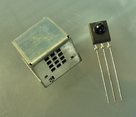
Figure 26.14. Metal-encased infrared photodetector to suppress false signals due to electrical noise (left) and standard Panasonic PNA4602M infrared photodetectors (right)
By observing the time between the appearances of a signal, an appliance can decode commands, which is the basis for remote control. In fact, the target market for these parts is actually the remote control industry (VCRs, TVs, and stereos). That large audience has caused the standardization of the signal frequency and dramatically decreased price of the parts.
Some robots surround themselves with photodetectors. By turning on different infrared LEDs at different times, and then reading each of the photodetector's outputs, the robot can get a rough idea of the locations of nearby objects. Other robots use the photodetectors in a classic way, as a remote control, or in a fancy way, as a method of data communication.
Standard and remote control photodetectors can tell a robot whether an object is nearby, but can't tell the robot exactly how far away the object resides.
Sharp makes a variety of fantastic distance sensors (see Figure 26-15) with which the robot can determine not only if an object exists, but also how far away the object is. The sensor emits an infrared beam and detects the angle of return in a lens. It can detect objects and walls at distances between 10 cm and 80 cm.

The distance sensor is available with either a digital-numeric output or a variable-voltage output. You could mount a pair with variable-voltage outputs slightly forward on the sides of the robot, replacing test point 1 and test point 2 of the line-following robot's brightness sensor. In that case, Sandwich might be able to drive down a corridor, centering itself.
You can learn more about Sharp distance sensors by visiting http://www.robotroom.com/DistanceSensor.html
Oscillators provide accurate timing to microcontrollers, power converters, motor controllers, or any time-sensitive circuit. The timing signal, often called "the clock," provides the drumbeat that keeps all the chips and components working together at the same pace, like clockwork.
Crystals are a portion of an oscillator circuit. The crystal itself has a natural vibration that can be converted to an electrical signal, and then amplified by other components in an oscillator circuit. A canned oscillator is a component that consists of the crystal plus the rest of the oscillator circuit inside a single piece.
For breadboard applications, oscillators are available in the space-saving half-can size (see Figure 26-16) and the full-can size. Or, you can purchase crystals separately, which is better for microcontrollers that have the ability to multiply the base crystal frequency to speed up or slow down for power savings.
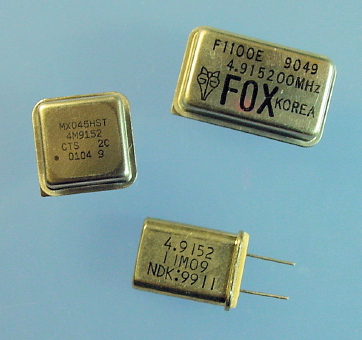
Figure 26.16. Half-can oscillator (middle left), full-can oscillator (top right), and crystal (bottom)
When someone asks, "How fast is your computer?" and you answer 2.6 GHz, you're actually giving a number related to frequency of the crystal or oscillator. If your robot has a microcontroller, it must have an oscillator. To make things simpler, the newer microcontrollers often have a fairly well-timed oscillator built-in.
You can add sound to a robot to enhance the theatrical effect (with music or funny noises), to provide a friendly interface (with speaking or button feedback), or to aid in debugging (by playing a certain noise when sensor readings are in a specific range or when you need to take actions).
Buzzers are the easiest to control (see Figure 26-17). Connect them to power, like you would a motor, and they make a predetermined noise, like an alarm. Speakers are much more versatile and provide a much higher-quality sound. Although tones and basic tunes can be played on a speaker without much effort, specialized chips are usually required to reproduce digitized sounds or music.
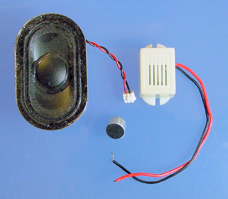
Voice recognition is difficult enough for high-powered computers, much less a robot. However, recording and playing back brief messages can be achieved with commercially available modules. For recognition of simple tones, a microphone and inexpensive chip will do.
One concern with transistors is the limited amount of power they can switch. Relays provide a switching function similar to transistors, but allow much higher voltages, greater current, and even different voltage types (such as DC controlling AC). Most importantly, mechanical relays allow one circuit to control an adjacent circuit that has a completely separate power source.
A typical mechanical relay (see Figure 26-18) has an electromagnet that physically moves metal plates together to connect. This physical switching explains why some relays make a distinctive clicking sound during operation. When power is disconnected, a spring, or the bent metal plates themselves, forces the metal plates back into their original position.
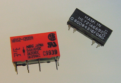
Because a bit of current (10 mA and up) is needed for the relay itself, a transistor often switches the power to the relay. So relays supplement switching—they don't replace transistors. In fact, because relays can be large, noisy, heavy, and relatively slow, they're usually employed only for heavy-duty jobs.
Some robots use relays for controlling large motors. That's understandable. But, for mid-sized and lunchbox-size robots, current-efficient transistors (called MOSFETs) are superior choices under most circumstances.
Gearhead motors contain tiny, precisely manufactured, precisely placed gears for optimal motor performance. However, that doesn't prevent you from adding additional gears (see Figure 26-19) to the motor shaft in order to alter the final output speed or deliver the rotation to a different location.
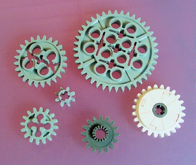
A robot tends to become fairly wide when you add wheels and couplers directly to a motor shaft with the motors placed end-to-end in the robot's body. Even if you are not trying to change the speed, you can still rearrange the shape of the robot by placing the motors side by side with pairs of gears transferring the motor power to a different location (see Figure 26-20).

There are four major types of DC motors usually found in robots. Plain DC motors and gearhead motors were covered in this book. Stepper motors are more precise but require complicated electronics to implement well. The last major type of motor is the servo.
Servos contain built-in electronics and gearing (see the right side of Figure 26-21) that position the motor shaft at a specified angle rather than continuously rotating. Servos are often found on model airplanes and model sailboats to control the angle of the wing flaps or sail.
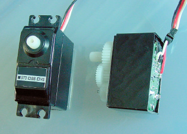
Out of the box, servos are wonderful for positioning arms and legs or for aiming sensors. By opening the cover and cutting away a couple of plastic notches, you can make a servo to rotate continuously, much like a gearhead motor.
A servo's built-in electronics handle motor power, eliminating the need for motor-driver transistors on the robot's main circuit board. Unfortunately, the command signals to a servo are timed pulses. Thus, a special module or microcontroller is required to control a servo.
Many robots could benefit from knowing the speed at which that their wheels are rotating. For example, Sandwich could improve turning by sensing when the "off" wheel slips forward, to which it would correct the pivot point by rolling the wheel back by the same amount. Another use of rotation information is that when a wheel spins faster than the loaded robot's mass should allow, the wheel is probably slipping or perhaps even off the ground.
By multiplying the number of rotations by the wheel size, a robot could determine the distance traveled. In fact, a line-following robot could store the course distances and turns made on the first lap, and then speed up in the straight-aways on subsequent laps. Or, a roving robot could find its way home by backtracking along the turns and distances it had traveled.
An encoder disc (see Figure 26-22) is placed on a shaft or wheel. By aiming photoresistors or phototransistors at the disc, the robot can tell how much the wheels or shaft are turning. All the robot needs to do is watch and count the number of transitions from black (high resistance) to white (low resistance). The greater the number of transitions per second, the faster the wheel is turning.
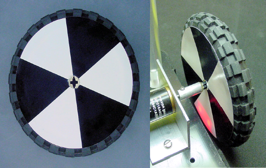
There are more complicated disc patterns, like Gray coding, from which the robot can tell the exact position of the wheel and in which direction it is rotating. There are adapters for motors, called encoders, which include a sensing technology and a circuit in a single enclosed piece.
Indicator LEDs are inexpensive, lightweight, and easy to add to a circuit. But, they only convey a limited amount of information. On the other hand, multi-segment alphanumeric LEDs, character-based LCDs (liquid crystal displays), and graphic displays are much friendlier and informative.
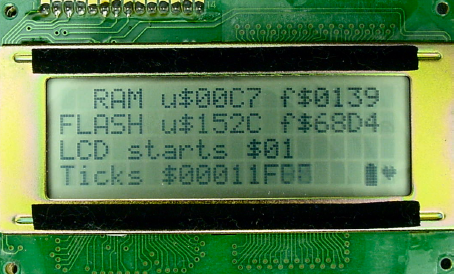
Character-based LCDs (see Figure 26-23) are available in a number of sizes, ranging from a small display of 8 characters by 2 lines up to a display of 20 characters by 4 lines. Most character-based LCDs communicate through an industry-standard 14-pin interface. Once you've learned how to control one, there's almost nothing more to learn to control the other sizes and styles.
Tip
LCDs consume much, much less power than LEDs. That's why solar-powered calculators use LCDs.
Other than the most basic LED displays showing simple numbers and a few characters, a decent display requires a microcontroller. I highly recommend attaching some sort of alphanumeric (numbers and letters) display to your robot's microcontroller, as it makes debugging so much easier.
Look no further than the common garage door opener or radio controlled (RC) toys for radio frequency (RF) controllers. There are lots of good robot-ready controller boards that are sold for model airplanes, boats, trucks, and cars. As robot combat television shows made obvious, model radio controllers are easily adapted for robots.
Some modules have features that can even provide data transfer rather than just control (see Figure 26-24). With data RF modules, the robot can remotely log sensor information to a laptop or desktop machine. Or you can reprogram the robot remotely rather than with a serial cable. Or the robot can receive status information about the environment (doorbell ringing, heat source detected on the couch in front of the TV) and communicate that information to a primary location, such as a home computer.
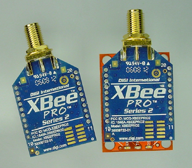
Perhaps the coolest potential opportunity for wireless data technology is the ability for multiple robots to work together on a task. RF modules are like miniature robot walkie-talkies.
I compiled a list of tasks that I think would be fun or helpful for a robot to perform. I constantly annoy my friends, family, and coworkers with statements like "Oh! That would be a great task for a robot." I notice that fewer and fewer people are eating lunch with me lately.
The robot normally sits on a charging base. Every once in a while, it would drive over to the sink and extend a telescoping tube to obtain some water (perhaps a floor-level copper outlet would be easier).
The robot would then wander through the house, stopping at predetermined spots that are perhaps marked on the floor to improve positioning. The robot would extend a telescoping probe up to reach the houseplants. With the probe, the robot measures the resistance of the dirt, thus determining the approximate moisture level.
If needed, the robot dispenses water into the pot. It proceeds on, visiting each plant, returning for water and power as necessary.
To weed a garden, a person normally plucks weeds and carries them along until their hands are full. The noxious weeds with seeds are disposed of as yard waste, but the majority of the plant matter is eventually deposited in a compost pile.
It would be very useful to have a robot that followed you throughout the garden. The robot would have a pair of small buckets for depositing weeds and vegetable matter. When the gardener tapped a large button (or whenever the mass exceeded a certain amount), the robot would speed away. The robot drops the first load at a predetermined location for yard waste and deposits the other load in the compost pile.
The robot would then return to the last known location of the gardener, using a heat-sensor to catch up or locate the person.
Someone with a remote control would drive the robot around the house to show the robot each of the wastebaskets. At daily intervals (or perhaps at night), the robot would repeat the pattern, either unloading the wastebaskets into a larger container located on the robot, or carrying the wastebaskets to a fixed container in a central location.
For the ultimate helper, the robot could even be given a doggy door to take the waste directly outside to the trash cans. Like in a bad sitcom, your family members would thank you for your neatness and thoughtfulness at empting the trash so regularly, and you'd just smile and wink.
Here's one that everybody laughed at.
You could attach a miniature robot with suction cup legs to any flat windowpane in the house while you perform other activities. The robot would be equipped with a tiny squeegee and cleaning solution. It would meander over the surface of the glass, cleaning as it went. After a while, you'd pass by and pop the robot off and put it onto a new window.
You could toss a weatherproof, drop-proof robot with an integrated solar panel onto the roof of a garage or a house. It would seek the gutters and discard leaves on a regular basis. During the winter, it would scrape off snow to prevent ice dams and to expose the dark shingles for absorbing more heat from the sun.
I guess after a hard rain you'd need to go and find the roof rat on the ground and chuck it back onto the roof.
You'd place a robot similar to the roof rat outside on the driveway when it started to snow. The robot would carry small loads of snow and deposit them in a specific location (a beacon of some kind would probably be necessary). Although the robot would relocate only small quantities at a time, usually snow doesn't fall that fast.
When I dared speak about this idea, people howled: "After a few hours, you'd walk outside to find your robot frozen into an ice block against a snow bank," and "No, no. You'd find that the robot was still working diligently, yet it's only accomplishment would be a network of snow caves and tunnels beneath a 4-foot drift."
This one isn't for the weak of heart, but it is for line-following robots.
In some areas, slugs and snails devastate home-garden vegetables. Organic gardeners are opposed to poison bait, and beer traps are only effective against lush slugs or really desperate neighbors.
You could take advantage of the slug's obvious weaknesses, its slow speed and fragile body. Place a line course across major slug trails around your grounds. The robot would sleep when it was hot or dry, like slugs. However, at night or when it was damp, the robot would speed along the line course, slicing up or smushing any slimy critters in its path.
You'd need to calculate the maximum course length based on the best-case slug speed and the robot's width.
This one is actually a pretty good idea. In rural areas or certain housing developments, the mail is delivered to a mailbox that is detached from the house, usually quite a distance away.
In this scenario, the robot would look like an ordinary mailbox. After anything is loaded into the mailbox (detectable by a photointerrupter beam), the robot would wait a short period of time to avoid scaring the postal worker. Then, the robot would drive the mail into the house via a doggy door and dump the mail at a predetermined location before heading back to its post. For security reasons, the doggy door could be locked with an infrared security signal to open it.
There are a couple of United States autonomous-robot contests worth mentioning. By autonomous, I mean no human beings with remote controls. There are also some contests aimed at professional electrical engineers or graduate students, but they're not appropriate to mention here.
If you don't find any of these contests appealing, or if you are located too far away, consider establishing a contest in your own area. You'd be surprised at the positive response of local libraries or museums to the idea of hosting or providing facilities.
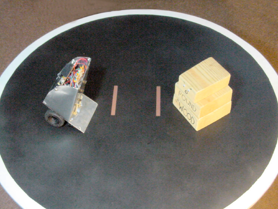
Robot Sumo is a non-violent pushing contest between two robots. The robots dual in a flat black ring with a white border (see Figure 26-25). The robots can detect the white border using the same technology that detects the white line in a line-following robot. The first robot to be pushed out of the ring, or to fall out, loses.
An illustrated guide with complete details for Robot Sumo appears at http://www.robotsumo.com/.
Robot Sumo contests are held throughout Japan, Canada, the United States, and many parts of the world. In the United States, significant tournaments are held in Seattle, Washington; Peoria, Illinois; Portland, Oregon; San Francisco, California; Atlanta, Georgia; and in many other places. A few contests feature cash prizes, but most award wonderful parts and kits donated by commercial sponsors.
Probably the most attended and lucrative amateur contest in the United States is Trinity College Fire-Fighting in Hartford, Connecticut. Total cash to be awarded is over $10,000. The prize money is distributed among multiple divisions, so, there's a fairly good chance of obtaining an award. T-shirts and other goodies are provided to all who enter.
The goal of the contest is to extinguish a candle flame in the shortest possible time. The candle may be located in one of four rooms. The specifications for the course layout are published so that your robot may take advantage of wall mapping technology. There are optional complications that may be voluntarily selected by the robot builder to produce a better score.
You can find complete details at http://www.trincoll.edu/events/robot/.
The Atlanta Robot Vacuuming contest may provide the excuse you've been looking for to purchase as many robot parts as your heart desires, with the full support of your spouse, mother, or roommate.
The purpose of the contest is to vacuum as much rice as possible in four minutes or less. There are bonuses awarded for returning to the start, using less than the four minutes allotted, and for lighter-weight robots. Penalties occur for pushing or knocking over furniture. It is perfectly acceptable to add some beacons to help guide the robot, which isn't the case in most other events.
You can view photographs, see past years' scores, and obtain additional information from the Atlanta Hobby Robot Club's web site (http://www.botlanta.org/). They don't hold the robot vacuuming contest every year (it depends on interest levels), but that doesn't prevent you from hosting a contest in your local area.
Every year, the Seattle Robotics Society holds Robothon, an open house gathering of robots, robot enthusiasts, resellers, and members of the public. At that event, not only do they hold Robot Sumo and Fire-Fighting contests, but they also hold other contests such as line following and maze solving.
It's worth attending Robothon even if you don't have a robot to enter in the contest. For more information, including their newsletter, meeting minutes, and photographs, visit http://www.seattlerobotics.org/ or http://www.robothon.org/.
The Dallas Personal Robotics Group (DPRG) features some of the more practical contests, which are very inviting to people just getting started. Using a specified arena, four different tasks are presented, one at a time.
Quick Trip – The robot drives straight from one end of the arena to the other, and then back again.
Line Following – An easy course shaped a little like the outline of a letter "T" on its side.
T-Time – The same T-shaped course without the line. The dimensions are published in advance, walls surround the arena, and solid lines appear before each corner of the T. So, there are a number of simple ways to effectively tackle the course.
Can-Can – The most challenging, but the most interesting as well. The robot has up to ten minutes to fetch up to six empty soda cans placed upright throughout the arena.
From year to year, DPRG Roborama features additional contests. For details, visit http://www.dprg.org/competitions/index.html.
In the Midwest, the Central Illinois Robotics Club holds an annual robot contest. They have a great turnout from many surrounding states, in a family-friendly, kid-friendly atmosphere.
Although emphasis is placed on several different-size classes of Robot Sumo (including a LEGO division), they also dabble in line following. I've attended the event in the past and plan to again in the future. Maybe I'll see you there?
To learn more, visit http://circ.mtco.com/.
Last, but not least, is my hometown robotics club. Chibots holds regular meetings in the northwest suburbs of Chicago. They also hold a bi-annual event at the Chicago Museum of Science and Industry and the iHobby Expo. Chibots has defined rules for over a dozen different robot contests, which are held based on registration.
Their web site is http://www.chibots.org/.
I hope this book has given you the confidence, knowledge, and enthusiasm to send you headfirst into robotics. There's plenty to do and lots of interesting projects to start. You couldn't have picked a better time to begin this fascinating and rewarding hobby.
Thank you for reading this book. It was a real joy to write.