
This chapter begins with last-minute checks followed by a qualifying run of your line-following robot. I provide you with simple tests for diagnosing and solving likely problems, and data to compare your robot to mine. The chapter concludes with line course ideas and potential robot enhancements.
Don't expect your robot to run perfectly on the first try. There will be bad connections, loose screws, burrs, and things rubbing. Because of an early collision, Wavy stalled every few feet. After days of wasted effort concentrating on the electronics, it turned out that a cross axle hadn't been glued properly in a coupler and was slipping. These things should be expected.
Be prepared to spend as much time tweaking the "finished" robot as you did in other phases of the project. Logically, a properly adjusted robot performs better than an unadjusted robot. Minor alterations are often the difference between success and failure.
Before setting the robot onto a track, there are some important basic tests and calibrations to perform. This ensures the robot is road-worthy.
Test the circuit board with a multimeter before applying power. For a list of tests to perform, see the end of Chapter 23.
Toggle the line-following switch to the center (off) position.
Turn on the power switch.
If neither the headlights, brightness indicator LEDs, nor tube LEDs turn on, then something is wrong with the power supply module. Check the voltage of the battery, battery connector, power switch, and power switch connector. Measure the voltage at different points in the circuit to see where it may be dropping off.
The board has four deliberately-added test points (TP+, TP-, TP1, TP2) for testing battery and sensor voltage. However, every exposed solder point, component lead, and connector pin can be considered a test point. It is often helpful to probe the voltages of each point with a multimeter. Is pin 4 of IC1 (the comparator) around 0 V and pin 8 around 9 V?
If only the headlights or tube LEDs don't light, it could be that one or more of the LEDs are backwards. The tube LED connector may be loose or have its wires reversed. The trimpot for the headlights might be set at too high of a resistance.
In a modular robot or in a robot that uses a lot of connectors, a great diagnostic trick is to disconnect everything that is unnecessary. You can test each part on its own. And, you can reinstall one part at a time until the robot stops working again. For example, the motors and tube LED can be disconnected while diagnosing a headlight issue.
Parts can also be swapped. If the motor on the left side doesn't work, try swapping it with the motor on the right side. If the motor suddenly starts working on the left side, then you know the issue is with the motor that you exchanged. If neither motor works on the left side, but both motors work on the right side, then you know the issue is with the left side of the circuit.
At no time should any of the parts become hot. If the transistors, comparator chip, or any other component seem to be heating up, disconnect power immediately. Make sure errant solder blobs or metal leads aren't resulting in unintentional connections.
Place the robot on a solid, evenly lit, non-patterned surface, such as a large white piece of paper. The goal is to make sure the sensors are seeing the same amount of light.
Slide a thin dark piece of paper back and forth under the sensors. The brightness-indicator LEDs on the left and right sides of the robot should light up alternately.
If neither sets of brightness-indicator LEDs light, compare the wiring of the soldered circuit board to the solderless breadboard. Is the comparator chip or any of the LEDs in backwards? Is the comparator damaged? Since the comparator is socketed, it's easy to pull it out and put it into the solderless breadboard version of the line-following circuit for testing.
If both sets of LEDs turn on and turn off at the same time (rather than alternating), then check the wiring between the sensor test points and the comparator. Perfectly balanced sensors may appear to light both LEDs at the same time, but putting your hand under one set of LEDs should be enough to break the tie.
If one set of LEDs turns on and off, but the other set always stays off, there's likely a broken connection or reversed LED in the set that stays off.
If one set of LEDs always stays on and the other set always stays off, then maybe the trimpot (R2) for balancing the sensors is not near the center. At the extremes of its range, the trimpot will imbalance one set of sensors so much it always seems to be brighter or darker.
Remove the dark piece of paper. With only the evenly lit piece of white paper beneath the sensors, dial the trimpot so that the left and right brightness indicators light up at the same time.
Sometimes it isn't possible to get both sets of LEDs lit at the same time. A tiny nudge of the screwdriver causes one side to light, and a tiny nudge the other way causes the other side to light. But, that's close enough, and it indicates the sensors are evenly balanced.
Place a dark piece of paper under the right-side set of sensors. The left set of brightness-indicator LEDs should light.
Move the dark piece of paper to be under the left-side set of sensors. The right-side set of brightness-indicator LEDs should light.
If the indicator LEDs are lighting up the opposite way, you can either start calling them "darkness" indicators (no, don't do that) or swap the comparator outputs to the transistors.
If neither motor turns, check the motor connectors, motor wiring, and line-following switch. If both motors always turn and stop at the same time (rather than alternating), check the connections to the line-following switch. If one motor turns and stops, but the other motor doesn't turn at all, check the failed motor's connector and wiring.
Another possibility is that the battery is weak or that the custom motors you picked require more power than a 9 V battery can supply. As a test, you can wire an LED and 1 kΩ resistor to a Molex connector to temporarily replace each motor. If the LEDs light, then the battery or motor are most likely to blame.
Due to the variety of battery chemistries, it is difficult to specify an exact voltage at which a 9 V battery would be considered "dead." Instead, it is easiest to swap in a fresh battery for test purposes.
Put a short piece of tape on the sides of each wheel. This will help you to be able to see in which direction the motors are turning.
Place your hand under the left or right sensors to make the left motor spin. The left motor should spin counter-clockwise (see Figure 25-1).
Place your hand under the opposite set of sensors so that the right motor spins. The right motor should spin clockwise (see Figure 25-2).
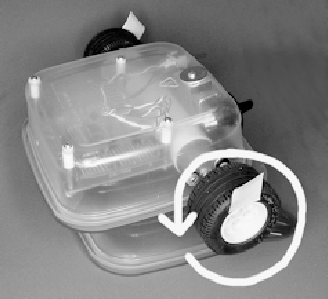

Having a motor spin backwards is the most common mistake in building this robot. It's confusing since one motor has to spin in the opposite direction than the other motor. Think about it this way: the tops of both motors must spin toward the front of the robot to move forward.
If both motors spin in the wrong direction, try swapping them to the opposite Molex connector headers on the board (so the left motor housing is attached to the right header connector on the board, and vice versa). Depending on how you wired the circuit, this may fix the problem. If that doesn't work, use a tiny screwdriver to pop both terminals out of each motor connector housing and re-insert the wires in the opposite order.
If only one motor spins in the wrong direction, you've got two possibilities. If the order of the terminals in the Molex connector housing of the "bad" motor are the opposite of the "good" motor, then pop and flip the terminals of the "bad" motor. However, if both motors are wired the same way, then the Molex header on the circuit board that connects to the "bad" motor should have its wires desoldered and flipped around.
If the left motor spins, then the line-following switch is in the position to follow dark lines. If the right motor spins, then the line-following switch is in the position to follow light lines.
Toggle the line-following switch to the right. The opposite motor should spin.
If the same motor spins as when the switch was toggled in the opposite direction, then the line-following switch is miswired. Most likely the motor wires don't diagonally cross over the center of the switch.
Label which position of the line-following switch is for light lines and which for dark lines.
To label the switch, I printed and cut out a 2 cm square piece of paper (see Figure 25-3).
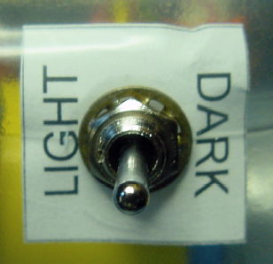
Figure 25.3. A printed piece of paper inserted inside the container for labeling the line-following switch
I cut a hole in the center of the paper with an ordinary paper punch. The switch bushing goes through the center of the paper so the paper is sandwiched between the switch's locking washer and the inside of the plastic container. If the paper had been mounted on the outside of the container, the paper would have become torn and soiled over time.
Tip
You can add decorations or a nameplate to your robot in the same manner as the line-following switch label. Simply put the piece of paper on the inside of the container, sandwiched between the washers of the standoffs that hold the circuit board.
The first test track for the robot should be a straight line.
On an indoor, flat, non-patterned, evenly lit, light-colored floor, place more than 4 meters length of 2.5 cm wide dark tape in a straight line.
A line-following robot couldn't ask for better racing conditions. The course may seem rigged for success, which is exactly the point.
It's like the high jump. Competitors start with the bar at lower levels, which they rightfully expect that they can clear. After you're assured that the robot is fully operational, then start increasing the difficulty of the course and conditions.
Note
As appealing as a sidewalk may look in daytime, the bright sun overwhelms the sensors, resulting in very small voltage differences to compare. Covering the container in thick, opaque tape helps. But, it is still a tough challenge for a robot designed for indoor lighting. So, avoid outside courses.
With the line-following switch in the center (off) position, place the powered-on (yet motionless) robot on the floor, centered on the dark line.
You can tell when the robot is truly centered by observing the left and right brightness indicator LEDs. Either they'll both light up or they'll alternate with the slightest nudge in either direction.
Toggle the line-following switch to the dark-line position and watch the robot go!
Sandwich takes between 12 and 15 seconds to complete a straight 4-meter course. The time varies based on battery voltage. The speed decreases about a quarter of a percent per trial due to battery-voltage decline.
There are a couple of common problems that you might encounter during trial runs of the robot on a straight course.
If the robot doesn't center on the line, but sort of hugs the outside or inside of it, the line-following switch is probably toggled in the wrong direction. It's an odd effect (and worth trying purposely for fun).
If the line-following switch is set to follow a light line but the robot is actually placed on a light surface with a dark line, then the robot sees the light surface as a massively wide light line. The robot moves into the light area until the light is balanced under both sensors. The robot believes it is now centered over the white "line."
But, no matter how balanced the trimpot adjustment may seem, at some point one set of sensors is still a little less resistive than the other set and one motor has a bit more spunk than the other. So, the robot drifts until it hits the side of the dark line. Because it wants to center over the nonexistent white "line," it turns away from the dark line because the white "line" is no longer centered under the robot.
As long as the robot's default drifting side turns toward the dark line, the robot will hug the outside of the dark line, basically following it. Then again, if the robot's default drifting side turns away from the dark line, the robot will either wander away aimlessly, centering over this massive light "line," or the robot will spin in a circle because it has nothing to follow.
The correction is simple; just toggle the line-following switch the other way.
The headlights must be high enough off the floor to have enough distance for the emitted light to illuminate the floor and bounce into the sensors (see Figure 25-4).
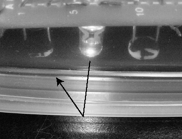
If the headlights and sensors are too near the floor, only fringe amounts of light (if any) can bounce off the floor and into the sensors. The sensors will be unable to tell the difference between a light-colored surface and a dark-colored surface; everything will look dark due to lack of light.
If the headlights and sensors are too far from the floor, stray ambient light from the room will bounce off the floor and affect the sensors more than the light from the headlights does. As such, the robot may begin following bright spots and room shadows, which is admittedly amusing. Placing some opaque tape across the front of the robot helps a lot, but doesn't look as stylish.
If you determine that the headlights and sensors are too high or too low, you can adjust the circuit board's mounting hardware. You can add additional washers above the circuit board to bring the sensors nearer the floor. To move the sensors away from the floor, remove the inside upper washer or either cut the spacers/standoffs shorter or substitute them with shorter pieces.
Take a closer look at the bottom of the photograph in Figure 25-4. Notice that the surface beneath the robot is black. But, directly beneath the headlight, the glossy black surface appears mottled white. If the headlights are too bright, the sensors will be unable to tell the difference between a light-colored surface and a glossy dark surface reflecting too much light; everything will look light.
On the other hand, if the headlights are too dim, they won't be contributing a reliable and predominant light source to the sensors. The room's ambient lighting and shadows will negatively affect the robot's line-following ability.
Fortunately, it's easy to adjust the brightness of the headlights with the associated trimpot (R10). After adjusting the headlight brightness, it may be necessary to rebalance the sensors using trimpot R2. This is because each headlight LED likely produces a different amount of light than the other LED. Adjusting the amount of current flowing through the headlight LEDs may alter the total difference in brightness between them.
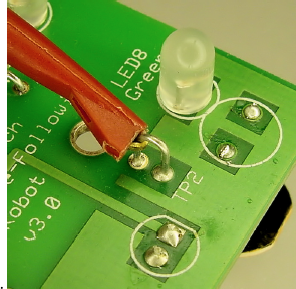
Adjusting trimpots and circuit board position by intuition may seem a little unscientific. For measurable results, you need to be able to test the voltage at the sensor's test points, TP1 and TP2. After all, that's what the comparator is looking at.
Grind a hole of approximately 1 cm in the side of the robot's body. Or, you could put the hole in the rear. Thread three IC hook jumper leads through the hole (see Figure 25-5). One jumper lead should be connected to the negative power bus (or negative power test point).
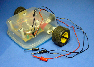
Figure 25.5. Hole in the side of the robot's body with IC hook jumper leads inserted for measuring the voltages on the board during operation
The other two jumper leads should be hooked to TP1 and TP2, respectively. If you didn't specifically make a loop of wire for each test point (see Figure 25-6), simply connect the hooks to the first and third leads of trimpot R2.
With the robot powered up but with the line-following switch in the center position (motors off), manually place the robot over various points in the course. With a multimeter, measure the voltage at the test points to determine how easy it would be for the comparator chip to compare them.
To measure the voltage of the test points, the black test lead of the multimeter must be connected to the IC hook jumper lead of the robot's negative power bus. The red test lead of the multimeter can be hooked up to the IC hook jumper lead for either TP1 or TP2, but not both at the same time.
Adjust the brightness-balancing trimpot (R2) and the headlight-brightness trimpot (R10) and observe the effect on the measured voltage of each sensor test point. With an external light, such as a flashlight, light up the floor and cast shadows under the sensors to determine if the ambient contamination significantly affects the outcome.
The results of these experiments are not applicable if you lift up the robot from standard course position. You want to test what the robot is experiencing under racing conditions.
After balancing the sensors and adjusting headlights, what follows are the voltages I measured on Sandwich. Compare your voltages to mine. Recognize that depending on how fresh or drained your battery is, your robot is unlikely to have the same voltages that Sandwich did. Simply scale the numbers to determine if your robot is roughly similar.
Note
I covered Sandwich with a cardboard box during testing to avoid deviations due to ambient lighting and shadows. During these tests, Sandwich is actually supplied power from a wall transformer, because a dropping battery voltage would skew the values of the last tests performed.
Positive power bus: 9.07 V
Be sure to measure the voltage at the power bus, not at the battery. A battery disconnected from a circuit produces higher voltages than it does under load. Also, if a diode is added to the line-following circuit to protect from reverse installation of the battery, then a bit more voltage is dropped before reaching the rest of the circuits.
TP1 and TP2 on white paper:     2.036 V and 2.034 V
TP1 and TP2 on black paper:     7.54 V and 7.40 V
Sandwich's brightness-balancing trimpot (R2) was adjusted on white paper. Notice how the static value fails to balance the sensors at darker levels. The white-paper test-point voltages are similar to each other, but the black-paper test-point voltages are not as similar to each other. No big deal. Just remember to rebalance the sensors on the course at race day under local lighting and surface conditions.
1-inch wide blue masking tape beneath right sensors on black paper,
TP1 and TP2:    4.43 V and 7.13 V
1-inch wide ordinary masking tape beneath right sensors on black paper,
TP1 and TP2:    3.098 and 7.02 V
1-inch wide strip of shiny aluminum foil beneath right sensors on black paper,
TP1 and TP2:    2.374 and 7.21 V
1-inch wide strip of white paper beneath right sensors on black paper,
TP1 and TP2:    2.134 and 6.88 V
A couple of interesting results:
The robot can see the difference between blue tape and black flooring. The blue tape is a little above the middle of the robot's brightness range.
Ordinary masking tape (slightly tan) is less bright than white paper.
Aluminum foil doesn't diffuse as much light as white paper.
The lower resistance of the photoresistors on the right side has a voltage-reducing effect on TP2. However, light reflecting off the surface in front of the right headlight also seems to be reaching the left sensors depending on the surface material. Note the fairly low TP1 voltage, but fairly high TP2 voltage, for aluminum. Perhaps a physical barrier between the two sets of sensors might improve performance?
1-inch wide blue masking tape beneath right sensors on white paper,
TP1 and TP2:    3.604 V and 2.065 V
1-inch wide strip of black paper beneath right sensors on white paper,
TP1 and TP2:    4.93 and 2.075 V
The comparator will not switch correctly if both test-point voltages exceed the positive power bus's voltage minus 1.5 V. For example, a 9.07 V bus permits comparisons up to 7.57 V (9.07 V – 1.5 V). The sensors are not getting enough light if a line exists but both test-point voltages are that high.
In Chapter 23, the section "Tweaking for Better Performance" includes instructions for optimizing R9 and R1 for your robot's white LEDs and sensors. If you previously chose to stay with the default 150 Ω values, but your sensor test points routinely exceed the upper 1.5 V limit, then you probably need to remove those resistors. Replace R9 with 100 Ω for increased brightness and replace R1 with 22 kΩ for a larger voltage drop.
The comparator won't differentiate precisely if both test-point voltages are too similar to each other. That's desirable if the surface has the same brightness (a blank piece of paper) and the sensors are properly balanced. But, that's a big problem if the line to follow is beneath one set of the sensors! Look for a difference of at least ±1 V between the set of sensors with the line and the set of sensors without the line.
If both sensors are below 1 V most of the time, the sensors are getting too much light.
After fine-tuning the trimpots and the circuit board's position, be sure to move the robot into the brightest, darkest, most shadowy, most contrasting, and least contrasting situations to ensure the voltages meet the comparator's requirements under all conditions.
Now is a good opportunity to observe and explain that the robot doesn't quite drive straight.
Except for brief moments when both sets of sensors are receiving exactly the same amount of light, both motors are not turned on at the same time. This means the robot rarely drives straight forward. Instead, the robot shuffles left and shuffles right so the overall direction averages out to be straight.
Figure 25-7 consists of three frames showing the motion of the robot following a dark line. The robot's angles in these pictures are exaggerated for illustrative purposes.
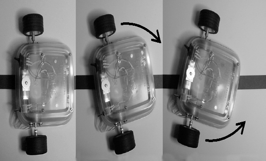
The first frame shows the robot perfectly centered over the black line. Both sets of sensors see white floor with a bit of black at the inner edge. The overall brightness is balanced, so both sets of LEDs and motors are enabled.
But floors, tires, and motors are naturally uneven. Eventually the robot drifts off course.
The second frame shows that the robot has drifted and that the black line is beneath the right-side set of sensors. That means the left side is brighter, so the left LEDs and motor kick in and the right LEDs and motor are disabled. With only the left motor spinning, the robot's left side will rotate toward the line.
At some point the sensors become balanced again, but because the left side is already in motion, the robot overshoots the line a little before the right motor can come up to speed.
The third frame shows that the robot has overshot and that the black line is now beneath the left set of sensors. That means the right side is brighter, so the right LEDs and motor kick in and the left LEDs and motor are disabled. With only the right motor spinning, the robot's right side will rotate toward the line.
This pattern repeats over and over very quickly but without such radical overshoots in reality. That's how the robot keeps centered over the line!
Figure 25-8 consists of three frames showing the motion of the robot following a light line. The robot's angles in these pictures are exaggerated for illustrative purposes.
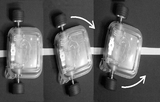
The robot proceeds in the same manner as it did for following a dark line. The vital difference is that the line-following switch has swapped the motor wires.
The first frame shows the robot centered, with the sensors balanced. Both sets of LEDs and motors are enabled.
The second frame shows the robot has drifted and that the white line is beneath the right-side set of sensors. That means the right side is brighter, so the right set of LEDs are enabled, but the line-following-switch swap causes the left-side motor to engage. The left side of the robot will rotate toward the line. If the right motor had been engaged instead, the robot would have continued moving off course.
The third frame shows the robot has overshot and that the white line is beneath the left set of sensors. That means the left side is brighter, so the left set of LEDs are enabled, but the line-following-switch swap causes the right-side motor to engage. The right side of the robot will rotate toward the line.
Very sneaky!
After you have checked the robot over and calibrated, it's time for the maiden voyage.
Laying out a track with masking tape is fun, because you can rapidly extend the course or quickly make changes to turns or intersections. Oval or "8" shaped courses allow you to sit back and admire your work, rather than having to pick up the robot and return it to the starting line.
Forks and splits in the road are interesting. Obviously the robot isn't making an intelligent decision about which road to take, but it's entertaining to alter the split until the robot starts taking different branches at random.
Don't forget to add tunnels to drive through or block walls to knock down. Hang bells on strings for the robot to ring as it drives by. Maybe a finish line?
If the robot is struggling to complete certain turns, there are three simple changes that you can make to significantly improve performance.
A fresh alkaline battery produces around 9.5 V. In comparison, after a couple of runs around the track, a low-end NiMH battery produces a nominal voltage of around 7.2 V. The fresh alkaline battery causes the robot to drive 32% faster.
As the battery voltage drops, so does the robot's speed. This gives the sensors more time to adjust to the changing surface brightness and prevents overshoot due to motors engaging and disengaging. Ultimately, the slower the robot proceeds, the better it turns.
This causes an interesting phenomenon. Upon discovering that the robot can't complete a certain turn, the builder makes adjustments to the robot and the course. After a number of attempts, the robot starts to consistently make the turn. The builder congratulates himself or herself on the alterations, only to discover the robot can't make the turn the next morning. The actual source of improvement was likely the decline in battery voltage.
At first, you may be offended at the thought of intentionally slowing down the robot. After all, doesn't greater speed imply greater capability? Well, if you find yourself disappointed with the robot's line-following aptitude, then perhaps the ability to follow a line is in fact a greater indicator of capability than is pure speed.
Potential solution: Replace those old 9 V batteries in your smoke detectors with fresh ones and use the depleted batteries to follow lines. Alternatively, switch the robot to a 6 V battery pack consisting of 4 AA or 4 AAA cells. With such a pack, the robot runs more accurately and lasts longer.
This is an easy one. If your robot is popping wheelies (the front end is lifting up temporarily at the start of the course), the wheel diameter is too large.
Wheel size makes a tremendous difference in speed, which makes all the difference in the ability to turn. The most successful change I made in Sandwich during development was to switch to smaller-diameter wheels.
Let's face it; you're a cruel course designer.
At first you may not think that you're being unfair or unkind to the little robot. But, consider this: How well could you make a turn in your automobile if all you were allowed to look through were a slit in the floorboard? You'd sure miss a lot of those 90° turns! Especially if you were driving fast.
Review the course requirements presented toward the beginning of the book. Keep the course turns gradual and with high contrast.
Several potentially beneficial design changes to the line-following robot have already been mentioned throughout this book:
Cover the clear plastic body with something opaque so that ambient light won't affect the sensors as much.
Switch to a 6 V rechargeable alkaline battery pack for improved cornering (due to reduced speed) and longevity.
Use an improved yet completely compatible comparator chip such as the National Semiconductor LMC6772 to accept sensor voltages in the upper 1.5 V region.
Place an opaque barrier in the middle of the robot between the left set of sensors and the right set of sensors. This should reduce the light coming from the surface of the opposite side of the robot.
Switch to wheels that are solid, round shouldered, thin, have a slick tread, and medium diameter for reduced rolling resistance and improved cornering.
Switch to more efficient motors for longer running time.
Add clear plastic to cover the window that was ground out of the lid. The plastic will prevent damage and dirtying of the sensors.
Use modern, smaller surface-mount components to reduce the circuit board to a quarter of its present size.
Obviously, you could completely redesign the robot circuit around a smart microcontroller. But there are a couple of other enhancements that you can make more simply.
The line-following circuit is fairly robust. It can operate within the entire voltage range of the battery's lifespan without the need for a voltage regulation module. The transistors can handle the current to the motors, even if the motors stall. Flyback diodes protect the transistors from motor spikes. Resistors protect the circuitry attached to trimpots from the operator dialing extreme values.
There is one common error that can harm the robot's circuits: inserting the battery the wrong way. If the 9 V battery is touched, however briefly, to the battery snap with the positive terminal and negative terminal reversed, and the power switch is turned on, the comparator chip could be destroyed.
There is an easy solution to protect against battery reversal. Between the power switch and the positive power bus, insert a diode (see Figure 25-9). Recall that diodes are one-way valves. As long as the battery power is going in the correct direction, the diode (D3) will let it pass. If the battery power is reversed, the diode blocks it.
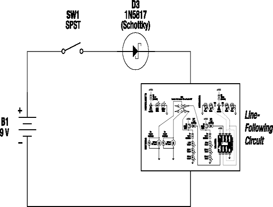
Be sure to place the diode so that the anode (plain end) connects to the power switch and the cathode (banded end) connects to the positive power bus. The diode should be the only "wire" connecting the switch and the bus.
There is a small cost or another benefit to adding the diode, depending on how you look at it. A Schottky diode drops up to 0.45 V in exchange for the service of passing current through it. This means the motors would receive a little less power, and would move at a slower speed.
Because this robot has a simple brain without memory, doesn't require voltage regulation, and has fairly insensitive circuitry, the robot isn't harmed by brief losses of power. That being said, I have noticed the LEDs dim a bit when both motors kick in at the same time.
Think of capacitors as tiny rechargeable batteries. They charge up when voltage is available, and discharge when voltage drops down. Although they don't hold much electricity, they can be used as local power sources when power has been diverted from the battery to the motors.
The electrical location and storage capacity of a capacitor determines its effectiveness in filtering spikes, electrical noise, and sudden current draws. For example, a large-value capacitor (thousands of microfarads) placed across the power buses can supply current to the entire circuit. Whereas a smaller-value capacitor can charge and discharge more quickly than a larger-value capacitor (thus smoothing out higher-frequency transitions), it has a lower capacity, and is therefore more suited for caring for only a few chips. The filtering effect is most pronounced on the chips nearest the small-value capacitor.
There are two appropriate locations for capacitors in the line-following circuit. You can attach the leads of a large-value capacitor, say 330 μF (microfarad), to the positive and negative power buses. That capacitor would be called C1. It can supply large amounts of power more quickly than the battery can, thus temporarily providing more than enough current for the entire robot each time a motor starts-up.
And, you could attach the leads of a tiny, 0.1 μF capacitor to the positive and negative pins of the comparator. That capacitor would be called C2.
Although they aren't necessary for this robot, capacitors are vital in more complicated circuits. Chapters 7 and 8 of Intermediate Robot Building by David Cook (Apress, 2010) discuss capacitor values, circuit locations, and capacitor chemistry in detail.
Cadmium-sulfide photoresistors react fairly slowly to changes in light. Phototransistors respond 1000 times more quickly. That suggests that substituting phototransistors for photoresistors would improve line following.
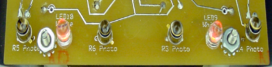
Figure 25-10 shows the photoresistors (R3, R4, R5, and R6) replaced with phototransistors, such as part #120221 from Jameco for $1.95 each. R2 must then be replaced with a 500 kΩ trimpot to retain the same levels of voltage division.
Surprise! After substitution, no noticeable improvement in line following was observed. That doesn't mean that the phototransistors didn't improve the responsiveness of the sensor circuit, it just means that something else was the critical factor in steering. Hmmm. What would that be?
To determine how the robot handles steering, I shot a video of the robot and analyzed each frame (see Figure 25-11). I apologize for the poor centering of the robot in the video, but the relevant material is still visible.
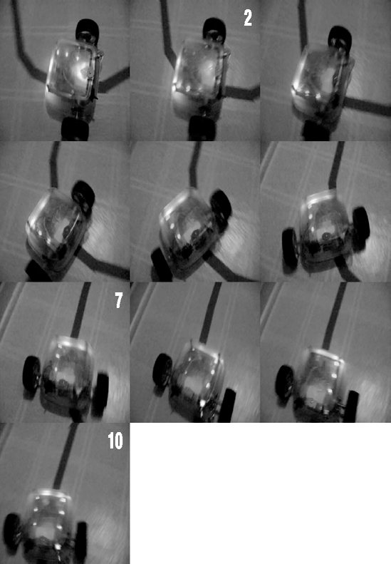
In the first frame, the right LEDs are lit. Since the robot is following a dark line on a light floor, the right motor must engage when the right LEDs are lit. By frame two, the left LEDs have been turned on, and only a brief residue of light remains in the right LEDs. So, at this point, the left motors are engaged but the power to the right motors has been disengaged.
Frames three, four, five, and six all show the robot properly powering the left motor to turn the corner. The right LEDs, and hence the right motor, are disengaged at that time.
By frame seven, both LEDs should probably have been lit since the curved line appears to now be centered. Both sets of LEDs are lit in frame eight, but by then the robot has oversteered. So, in frame nine, the right LEDs are lit and the right motor corrects the course.
In frame ten, the robot has both sets of LEDs and both motors engaged and is heading straight down the straight line. Beautiful!
There's a problem, though. Check out the position of the right wheel at the time the right motor was first disengaged (frame two). Now compare that to the wheel's position before the right motor is reengaged (frame seven). The wheel has continued to roll toward the line, probably about 6 cm (see Figure 25-12), even though the right motor is turned off.
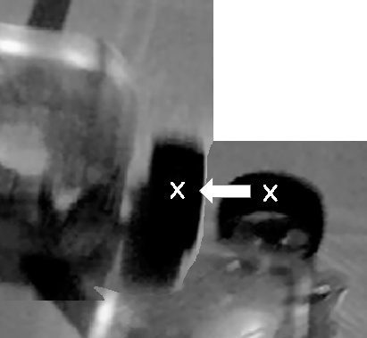
Figure 25.12. Frames two and seven superimposed to show wheel roll. If the wheel had stayed in place, the "x" marks would be directly on top of each other. (Please excuse the quality of this image; it came from a video camera. Even so, it does show that the wheel has moved forward instead of pivoting in place.)
To make tighter turns, the robot must pivot in place.
In order to pivot in place rather than allowing a wheel to roll forward, the robot needs to apply an electrical brake. It's easier than it sounds. In the present circuit design, when a motor is disengaged it is simply disconnected from the positive power bus. If instead it were then connected to the negative power bus, the motor would brake.
To achieve that, two more transistors would need to be added (one for each motor), and a push-pull comparator (or a pull-up resistor and a 4069 inverter logic chip) would need to be substituted. These are just suggestions; I'm not going to add them to the line-following robot in this book.
A major downside of braking the motors is that the overall progress of the robot will be slowed when driving straight. This is because the opposite wheel no longer rolls forward. To fix that, a microcontroller could be programmed to only apply the brakes when turning.
This is getting complicated! To truly improve the performance of Sandwich, it needs faster sensors, motor circuitry that can brake, and a microcontroller for better control. Not surprisingly, the line-following robot in Intermediate Robot Building has these features.
I hope you've enjoyed reading about Sandwich. Hopefully, you've even built one of your own.
If your robot isn't working as well as you'd like, don't get frustrated. Every great scientist anticipates and appreciates the opportunity for learning from every point of failure. The investment you make objectively examining this robot is actually time spent planning your next robot.
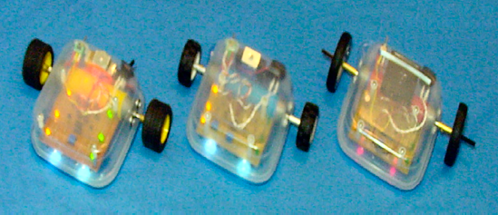
To that end, there were actually three Sandwich robots built while writing this book (see Figure 25-13). Each one consists of improvements I made from observing the advantages and disadvantages of the prior one. The improvements were then worked back into the book, so that you, the reader, see the most advanced design.
Now that you've been introduced to the fundamentals of robot building, where do you go from here? That's what the next chapter is all about.