
This chapter contains notes and other items not covered in the main portion of the book.
It begins with proper credit to Ohm's law, which describes the interdependent relationship between voltage, current, and resistance. Then, I come clean about some of the mistakes I made during development, so that you can avoid them yourself. Finally, the chapter concludes with an explanation and listing of the various labels for positive and negative power.
Most of the electrical formulas in the book are derived from Ohm's law. Therefore, it would be remiss not to directly describe the most valuable set of math equations for electronics.
Ohm's law describes the relationship between voltage, current, and resistance. If you have any two of those parts, you can instantly calculate the third. You can divide voltage by either of the other two parts, or multiply current and resistance together (see Figure 27-1). Let that triangle burn into your head and you'll never forget which part needs to be divided and which parts multiplied.
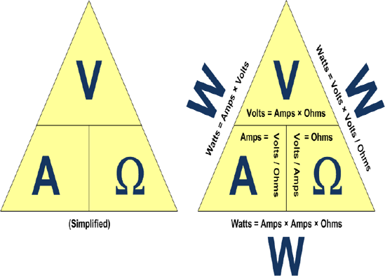
Here are the formulas expressed in a standard way:
current in amps = voltage in volts / resistance in ohms
or...
resistance in ohms = voltage in volts / current in amps
or...
voltage in volts = resistance in ohms × current in amps
All three formulas are identical. They've only been moved around algebraically.
Here's a practical example. According to some datasheet, the maximum current flow that some component can accept is 0.25 amps. You've got a 12-volt battery. What size resistor should you select to limit current flow to 0.25 amps or less?
According to the Ohm's law, if you know two parts, you can calculate the third. You know 0.25 amps and you know 12 volts.
resistance in ohms = 12 volts / 0.25 amps
48 Ω = 12 V / 0.25 A
A 48-ohm resistor will never allow more than 0.25 amps to flow through it when you're using a 12-volt battery.
You're worried about the robot's motors stalling and burning out. Based on the motor datasheet, the motor's stall current is 0.5 amps, but you've decided to have the robot shut off motor power if it reaches 0.4 amps, just to be safe. Unfortunately, almost all of the chips and microcontrollers only seem to be able to read voltage, not current.
Ohm's law guarantees that if you know the voltage and the resistance, then you can calculate the current. The solution is to put a known value of resistor in the same path as your motor and have the robot read the resistor's voltage to calculate the current in that path. Installing a low-value power resistor, say 0.1 Ω, should have little effect on the motor's performance.
voltage in volts = 0.1 ohms × 0.4 amps
0.04 V = 0.1 Ω × 0.4 A
When the chip detects 0.04 volts or more, then 0.4 amps or more are pouring through the motor. This must be true, since the resistor is in the same path as the motor, so any electricity passing through the motor must pass through the resistor.
Remember, this is magical, unbeatable Ohm's law. There's absolutely no way to get more than 0.4 A through a 0.1 Ω resistor unless the voltage dropped across the resistor is 0.04 V or more.
Ohm's law is helpful for measuring current on a soldered circuit board. You can't measure current directly with the multimeter unless you desolder one end of a wire somewhere to connect it through the meter in amp mode. But, if you can find a resistor with a value printed on it, then you can calculate the current after measuring the voltage across the resistor.
Let's say you find a 220 Ω resistor. You measure the voltage by touching the multimeter probes to each end of the resistor and it reads 3.52 volts.
current in amps = 3.52 volts / 220 ohms
0.016 A = 3.52 V / 220 Ω
In case you've forgotten, you can multiply amps by 1000 to get milliamps.
0.016 A × 1000 = 16 mA
16 mA must be passing through the path of the resistor, regardless of the stuff in the circuit before the resistor or after the resistor. Why? Mr. Ohm (Georg S. Ohm) guarantees it or double your money back!
Anytime you say to yourself, "I sure wish I knew A, but I can only measure B and C", think of Ohm's law. To assist you, I've created an online tool (see Figure 27-2) where you can enter two measurements and the site calculates all of the other values. Visit: http://www.robotroom.com/Calculators/Ohms-Law/Ohms-Law-Voltage-Current-Resistance-Calculator.aspx

There is an undeniable reality to Ohm's law: In a circuit, you can't change just one of the three terms (either voltage, current, or resistance). Any change in one causes at least one of the others to change to balance.
This also means you can purposely alter one term to force a change in another.
Sometimes after I read a good book about robots, I get a little discouraged. I think, "Wow, this guy's a lot smarter than I am. How can I be expected to build what he built?" The truth is that most authors only publish their successes, so of course everything seems perfect. You're not there to observe the junk he flung out of an open window.
Perhaps revealing my mistakes will prevent you from repeating them. Additionally, it may offer some explanations as to why I made a change in the robot's circuit and also warned you to avoid certain parts.
Let's face it, a 9 V battery is difficult to install backwards. But, it is possible for anyone to touch the battery to the wrong terminals of the battery snap, even briefly. That's no tragedy, unless you've left the power switch on.
In my case, the reversed voltage zipped through Sandwich's circuits. Each path with an LED was protected by the diode (one-way) nature of the LED. The photoresistors, resistors, and trimpots were safe because they're non-polarized devices, meaning they don't care in which direction current flows.
After correctly snapping the battery into place, it didn't occur to me that anything had happened. After all, I was looking at the bottom of the circuit board and the headlights and tube LEDs were now illuminated. But, frankly, something started to stink. The robot really smelled bad.
Upon flipping the robot right side up, I noticed the left and right brightness indicator LEDs weren't lit. After wiggling wires and flipping switches to no avail, I began to suspect that something was wrong with the comparator or transistors. Since the comparator was socketed, it was the easiest part to swap out. Indeed, the comparator was dead (see Figure 27-3).
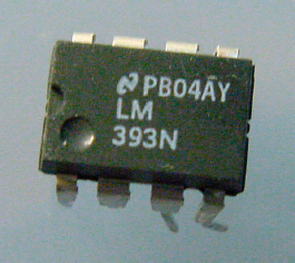
The comparator has a direct connection to the positive and negative terminals of the battery. The reversed battery with the power switch on was enough to fry the chip. This is why I introduced the Reverse Battery Protection circuit in Chapter 25 as a potential improvement.
The standard-size subminiature DPDT-center-off line-following switch seems a bit large for the line-following robot. So, I experimented with smaller, micro-size switches.
After wiring and soldering up a couple of micro switches (see Figure 27-4), they were installed in the line-following robot brothers. One robot spun in circles, and the other robot followed dark lines but not light lines. The switches made nasty, horrible crunching sounds when toggled.

Upon closer inspection, I realized the switches had melted and cracked during soldering (see Figure 27-5). I don't know whether the switches were of poor quality or if I held the soldering iron against their leads for too long.
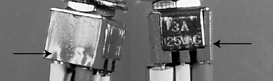
Larger pieces of metal do take longer to solder, so I believe the manufacturer should use material that can withstand being heated for a reasonable period of time. Due to this failure, I didn't end up recommending this particular model of switch in the book.
In the years I've practiced electronics, I've never blown a fuse in a multimeter (see Figure 27-6).

In writing a book, a lot of time is spent researching and validating facts. Since it's going to be on paper for a long time, with my name associated with it, I want the information to be reliable.
For the transistor chapter, I measured transistor gain in a multimeter transistor test socket. I wanted to verify that the multimeter was displaying an accurate value and that the amount of gain multiplied by the amount of base current determined the maximum amount of current allowed from the collector to the emitter.
With the transistors in a test circuit, I dialed the multimeter to amp mode. With this higher-rated mode, I tested the amount of current coming from the battery to ensure it was below the 500 mA limit of the meter in milliamp mode. The current was well below that limit.
I switched the multimeter to milliamp mode and disconnected one end of the resistor from the base lead of the transistor. I connected the red multimeter test probe to the base lead of the transistor and the black test probe to the negative bus. Poof!
I must have been thinking about measuring voltage. Instead, I should have connected the black test probe to the disconnected end of the resistor. The resistor is there to limit the amount of current provided to the transistor. By hooking the black test probe to the negative bus, I provided a short path from the positive terminal of the battery, through the transistor's collector lead, through the transistor's base lead, through the multimeter, to the negative battery terminal. There weren't any resistors in that path to limit current.
The current through the multimeter exceeded 500 mA, blowing the fuse inside the meter. The multimeter continued to display information ("0.0 mA") and operate in modes other than milliamps. I can't tell you how long I spent trying to figure out why the milliamp mode wasn't working.
Fortunately, the multimeter contained a spare fuse, and I was able to continue testing. This time, I connected the multimeter correctly and obtained the validation of the experiment.
After finishing a chapter, I let it sit for a few days. Then, I proofread it and redo the experiments according to my written directions before handing the chapter to the publisher.
Guess what happened? During proofreading, I blew the fuse again making the same mistake with the test leads (see Figure 27-6, again!)
Throughout this book, I chose to use the term "negative voltage." It's not inappropriate, and the battery is labeled that way. It's just a bit primary school or old fashioned. Okay? It's un-cool.
As you move forward in electronics, you'll run across other terms for voltages. It's worth knowing these modern labels, as you're going to encounter them on datasheets, schematics, books, and articles.
Figure 27-7 shows one of the most prevalent symbols in a schematic. Recall that this indicates the conventional return path for all power in a circuit. On a battery-operated circuit, the path indeed leads back to the negative terminal of the battery. However, this symbol is actually referred to as "ground" or "common."
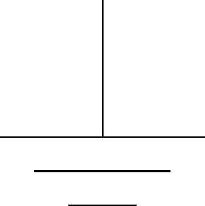
You can think of this as the lowest voltage possible in the circuit; 0 V; the power has reached the ground. You connect your black multimeter test probe to this location in the circuit and measure all positive voltages as being "above ground."
Nowadays, negative voltage suggests three power-supply voltage levels: a positive voltage, a ground, and a truly negative voltage that ground power can flow to. When speaking informally, there's nothing wrong with saying, "Hook one end of the motor to positive and the other end to negative." However, when there are really only two connections from the power supply, you should formally refer to negative voltage as ground, to prevent confusion.
With few exceptions, all integrated-circuit (IC) chips contain transistors. There are two kinds of transistors, bipolar and field effect. From an earlier chapter, you know that bipolar transistor leads are labeled collector, base, and emitter. Field effect transistors happen to be labeled drain, gate, and source.
When IC chips became popular in the 1970s, chip pin voltages were specified based on the internal part of the transistor to which they were connected. For example, the positive power supply pin would be labeled VCC. The C stands for collector, and is repeated (VCC) to indicate that it represents the voltage that the power supply for the collector should create. That's not necessarily the voltage at the collector (which would be VC).
The transistor pin labeling conventions continue today. No doubt you'll see them on everything from discrete transistor circuits, logic chips, all the way up to microcontrollers.
You may consider the following voltage terms positive voltage: +, V+, VBB, VCC, VDD, and VGG.
You may consider the following voltage terms ground (formerly "negative") voltage: -, V−, GND, common, VEE, and VSS.
On a 74LS04 (bipolar-based) chip, the power supply pins are labeled VCC and GND. The positive bus connects to the VCC pin and the ground bus (formerly "negative") connects to GND.
The power supply pins of a Freescale 68HC908KX8 (field-effect based) microcontroller are labeled VDD and VSS. The positive bus connects to the VDD pin and the ground bus (formerly "negative") connects to VSS.