Sandwich, the line-following robot, has a fairly simple circuit. Even so, at least 30 or 40 electrical connections need to be made. Consider what you have planned for your ultimate robot and you'll see that alligator clips are not going to be sufficient. In this chapter, you'll learn about a popular technology for experimenting.
When designing a robot circuit, mistakes will be made. Also, most builders throw in some new items with each creation in an endeavor to advance their knowledge. These two factors necessitate some sort of test phase, which is called prototyping. This is the time to try things before committing to a final design.
For electronic circuits, something is needed to allow easy switching of parts and rearrangement of wires to encourage experimentation. The prototyping technology should be inexpensive, stable, and accept the same components as the final device.
All in all, a few alligator clips are acceptable for temporary connections to either batteries or measurement equipment. Beyond that, engineers look to more stable methods of making connections.
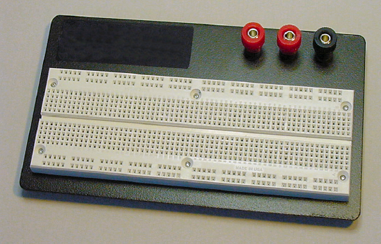
The solderless breadboard (see Figure 12-1) is a great prototyping solution. As the name implies, a solderless breadboard doesn't require any soldering. Wires and components are simply pushed into holes on the board to connect them together. No mess; no fuss. You can us the holes, wires, and components over and over again.
I always try out a new part or module design using a solderless breadboard. Although I often begin by thinking I'm fairly certain how a circuit is going to be built, a number of improvements are subsequently made because it's so easy to try variations on the breadboard.
Even after soldering together a final circuit, my original prototypes usually sit intact on their solderless breadboards. As long as I have spare parts (and spare breadboards), I retain the original for later experiments, debugging, or brainstorming.
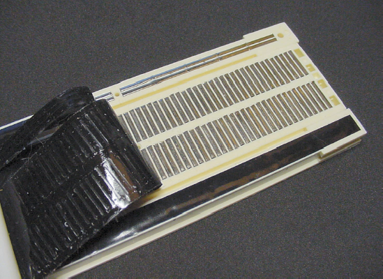
Technically, the holes in a breadboard are called tie points. When a wire is pushed into a hole, it makes contact with a solid metal strip underneath (see Figure 12-2). When another wire is pushed into a hole on the same strip, the wires are connected. The metal strip acts as a connecting pipe that allows electricity to flow from one wire to the other.
The holes are spaced every tenth of an inch. Underneath, each hole has individual metal prongs to firmly grip the wires or components that are inserted. Ideally, the component wires should have diameters from 0.38 mm to 0.81 mm (0.015 inches to 0.032 inches). Smaller wires tend to slip out or connect intermittently. Larger wires tend to jam and damage the hole or metal prongs.
Most of the holes on the breadboard are physically connected in groups of five. Any and all wires pushed into the five holes are electrically connected to each other (see Figure 12-3).
Put a wire in each of the five holes of the 5-position group and all five wires will then be connected. Or, put just a couple of wires in and they'll still be connected to each other, with a couple of empty holes remaining.
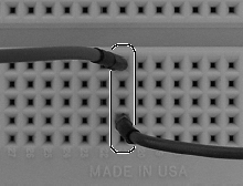
Adjacent groups are independent of each other. A wire in one 5-position group is not connected to a wire in an adjacent 5-position group (see Figure 12-4).

However, if you want to, you can connect 5-position groups together. Simply push each end of a single wire into a hole in each group (see Figure 12-5). This wire is now connecting together the two metal strips underneath. Anything connected to one strip is now also connected to the other.

There's a gap in the center of the board. A wire in one 5-position group is not connected to a wire in a 5-position group across the gap (see Figure 12-6).

The gap is designed for a DIP (Dual Inline Package), as demonstrated by Figure 12-7. DIP refers to the case style and size, not the manufacturer or the function of the part.
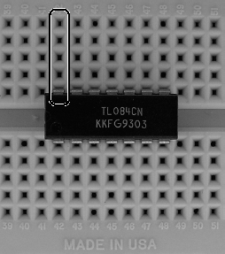
Place a DIP so that each pin connects to its own 5-position group. When properly placed, it just so happens that the middle of the part crosses over the gap. This makes it easy to insert a tool to pop out the part.
The part is in the wrong orientation if several DIP pins are left hanging in the gap (see Figure 12-8). Obviously, this makes it difficult to connect wires to the pins. Even worse, when placed in the wrong orientation, several DIP pins are connected to the same 5-position group.

At this point, you've probably got the board figured out. Everything is in groups of five. Well, what's the deal with the two leftover rows running the length of the top and bottom?
The two horizontal rows of holes at the top and bottom of the breadboard are called distribution buses (see Figure 12-9). Although they appear to be horizontal groups of five, they are actually connected underneath to a metal strip that is much longer, 25 holes.
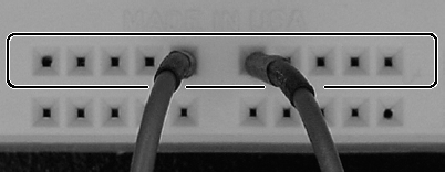
It's named the bus because it's long with many points along the way, like a real bus line. Getting on at one end can take you halfway across town, or you can get off at points in between.
There's a good reason why there are two rows of distribution buses at both the top and bottom of the board: Many parts in the circuit need nearby access to power. You can connect one of the bus rows to the positive end of the battery and the other bus row to the negative end of the battery. Now all the parts have convenient power access.
Depending on the length of a breadboard, the buses may be disconnected in the middle of the board. If you want the buses to run the entire length of the board, just connect the middle of each row with wire (see Figure 12-10).
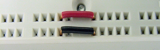
The fancier breadboards have binding posts (see Figure 12-11). They are not absolutely necessary, but the posts do make it easy to quickly connect and disconnect a power source without wear and tear on a breadboard hole or fragile wire.

Plastic caps insulate the binding posts. The caps are usually different colors. For consistency, use red for positive power and black for negative.
The plastic caps twist up to expose a small hole in the metal post. You can insert a wire through the post hole and screw the cap back down to hold the wire in place. You can then push the other end of the wire into a hole in the breadboard.
Atop the post is a jack (connection hole) for a banana plug.
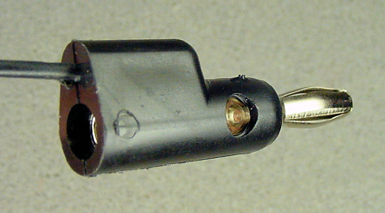
Banana plugs? You bet. Banana plugs kind of look like bananas on the ends, to the same extent that alligator clips look like alligators on the ends.
The nicer banana plugs include jacks in the middle and rear (see Figure 12-12) so that you can insert and connect additional banana plugs. A pair of insulated banana plugs connected by a wire is called a banana test lead.
Banana plugs are often found on test equipment, like meters and scopes, and also found on laboratory power supplies.
Breadboards are available in a variety of sizes (see Figure 12-13). The boards are usually classified by the number of tie points (holes). I probably have half a dozen of the 840 tie-point boards, as well as a couple of smaller 270 tie-point and larger 3220 tie-point boards. The 840-size makes a fine starter board (see Table 12-1).
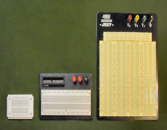
Table 12.1. Better-Quality Solderless Breadboards
Supplier | Part Number | Price | Tie Points | Binding Posts | Description |
|---|---|---|---|---|---|
SparkFun | PRT-07916 | $3.95 | 170 | none | Colored : PRT-08800 to PRT-08803 |
Electronix Express | 03SB02 | $24.50 | 840 | Three | 3M Solderless Breadboard |
Digi-Key | 922309 | $27.57 | 840 | Three | 3M ACE309 Solderless Breadboard |
Jameco | 20812 | $33.95 | 3220 | Four | Breadboard, Solderless |
The "where to buy" lists that appear throughout this book serve as examples of the characteristics of parts you might want to consider. The lists usually aren't supposed to be exhaustive. However, the breadboard price list (see Table 12-1) is exclusive. I don't recommend buying any other boards than these, as some of the other boards I've tried have been unusable.
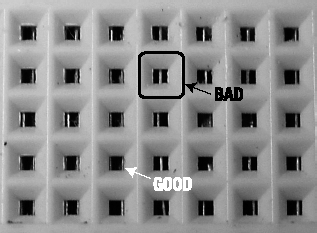
The metal strips in junky breadboards don't line up well with the holes (see Figure 12-14), causing parts to bend or resist as they are inserted or removed. A bad solderless breadboard makes the whole experience frustrating.
Tip
The holes in factory-fresh solderless breadboards tend to require a bit of exercising until they're conditioned. But after some use, the holes will hold firmly yet allow smooth insertion and release.
Although solderless breadboards tolerate a range of wire diameters, the best is insulated solid #22 AWG (American wire gauge - a size standard, not a company) hook-up wire.
For solderless breadboards, use solid wire instead of stranded (see Figure 12-15). Stranded wire consists of numerous smaller wires twisted together. The individual wires tend to separate and bend when being inserted into breadboard holes.

Ordinary copper (reddish-brown color) wire or tinned copper (silvery color) wire are equally good choices for breadboards.
Use #22 AWG size wire. Smaller diameters are a little loose in the holes and the wire tends to bend when being pushed in. Larger diameter wire jams the holes, often permanently forcing open the prongs of the metal connection underneath.
Use insulated wire. The rubber-like coating prevents unintended connections between portions of wires that accidentally touch. Also, the insulating coating is available in a variety of colors, which helps distinguish individual wires from each other (see Figure 12-16). At the very least, purchase red for positive power, black for negative, and some other color for signals (see Table 12-2).

Table 12.2. Insulated #22 AWG Copper Hook-Up Wire
Supplier | Part Number | Price | Length | Color |
|---|---|---|---|---|
Electronix Express | 270022BK | $1.05 | 25 feet | Black |
Electronix Express | 270022RD | $1.05 | 25 feet | Red |
Electronix Express | 270022GN | $1.05 | 25 feet | Green |
Electronix Express | 270022BL | $1.05 | 25 feet | Blue |
SparkFun | PRT-08022 | $2.50 | 25 feet | Black |
SparkFun | PRT-08023 | $2.50 | 25 feet | Red |
SparkFun | PRT-08024 | $2.50 | 25 feet | Yellow |
SparkFun | PRT-08025 | $2.50 | 25 feet | Grey |
SparkFun | PRT-08026 | $2.50 | 25 feet | White |
SparkFun | PRT-08027 | $2.50 | 25 feet | Brown |
Jameco | 36792 | $6.95 | 100 feet | Black |
Jameco | 36856 | $6.95 | 100 feet | Red |
Jameco | 36822 | $6.95 | 100 feet | Green |
Jameco | 36881 | $6.95 | 100 feet | White |
Jameco | 36920 | $6.95 | 100 feet | Yellow |
Jumper wires (see Figure 12-17) of various types connect components and tie-point groups together on a solderless breadboard. It's called jumper wire because it jumps from point to point, or at least it allows electricity to do so.

Reinforced jumper wire has sturdy metal posts on both ends covered in a rubber insulator. The rigidity and size of the posts makes it very easy to insert and remove the wire from the holes. The height of the posts extends over the top of components. The length of the wire allows for greater reach.
Common lengths for reinforced jumper wire are 50 mm (millimeter), 100 mm, and 200 mm. The 100 mm length is the most practical, although the shorter and longer lengths come in handy every once in a while.
The rubber-covered posts are finger friendly. They fit snugly, yet no tools are needed to move them around. Definitely stock your prototyping lab with lots of reinforced jumper wire (see Table 12-3).
Table 12.3. Reinforced Jumper Wire
Supplier | Part Number | Price | Length | Description |
|---|---|---|---|---|
Electronix Express | 2700WK1 | $9.50 | 3 ½ to 7 ½ inches | (30) black, yellow, red, white |
Jameco | 126360 | $3.95 | 2 inches | (10) Two each of yellow, white, red, black, and blue |
Jameco | 126342 | $5.95 | 4 inches | (10) Two each of yellow, white, red, black, and blue |
Jameco | 126325 | $6.95 | 8 inches | (10) Two each of yellow, white, red, black, and blue |
Ready-made jumper wire kits contain a wide variety of jumper lengths (see Figure 12-18). The lengths are designed to reach across a specific number of holes, although in practice they always seem a little bit long or a little bit short. The insulation color indicates the length of the wire.
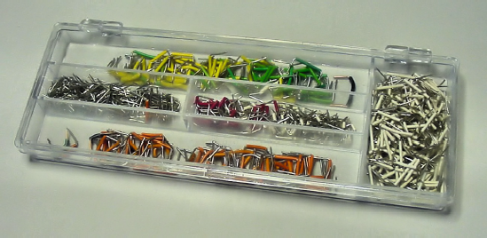
The wire is formed to fit flush against the breadboard, which makes for a neat appearance. The short height also permits access to components since the wire isn't crossing all over the place. The downside, however, is the wire can't cross over a component or another wire. A mix of the flat kit jumper wire (see Table 12-4) and tall-reinforced jumper wire is optimal.
Table 12.4. Flat Jumper Wire Kits
Supplier | Part Number | Price | Number of Jumpers |
|---|---|---|---|
Electronix Express | 2700MJW70 | $4.50 | 140 |
Electronix Express | 2700WJW60B | $9.50 | 350 |
Jameco | 19290 | $16.95 | 350 |
Digi-Key | 923351 | $32.14 | 350 |
Electronix Express has a nice combination package of 350 flat jumpers and 30 reinforced jumpers (various lengths) for $16.95, part # 2700RJW90.
You can make your own jumper wire. In doing so, you can get exactly the length you need with an insulation color that indicates the function (rather than the color indicating the length). However, it's not as convenient as the ready-made wire, and doesn't survive reuse as well as the reinforced jumpers.
To make your own jumper wire:
Begin by stripping off about 7 mm of the insulation from the end of solid #22 AWG wire (see Figure 12-19).
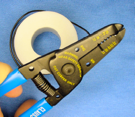
A large variety of wire stripper tools exist. I prefer those with numbered notches (see Figure 12-19) for each wire diameter rather than the adjustable or automatic wire strippers (see Figure 12-20). The numbered notches are exact, so you needn't worry about cutting into and damaging the wire itself. Also, no adjustment wheels need to be dialed to match the wire diameter—simply slide the wire into the correct notch. Table 12-5 lists some suppliers of notched wire strippers.

After stripping off one end of the insulation, cut the wire to the desired length. Don't forget to consider the amount of insulation you're going to strip from the other end of the wire.
Cutting the wire is faster if your stripping tool also has a cutter built in, as most do. If not, use flush wire cutters or nippy cutters.
After cutting, strip off about 7 mm of insulation from the other end of wire.
You can bend the wire into the desired shape with your hands. However, holding the wire in the tip of needle-nosed pliers and bending against the flat edge can achieve nice square corners (see Figure 12-21).
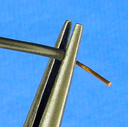
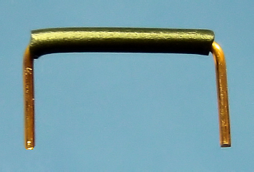
This bending trick also works well on component wires, such as resistors. That's it. Your jumper is ready (see Figure 12-22).
Besides wire strippers, a pair of needle-nose pliers is a tool you should not be without (see Figure 12-23). As with all tools, purchase the highest-quality tool you can afford. Fine tools are an investment that pays off every time you use them.
Look for smooth movement, clean edges, and grips that feel comfortable in your hands. Hold the pliers up to a light with the jaws closed. The light that seeps through the cracks between the jaws indicates places that aren't coming together completely. Check the tip for horizontal alignment.
Needle-nose pliers should be long and skinny. That's how they get their name.
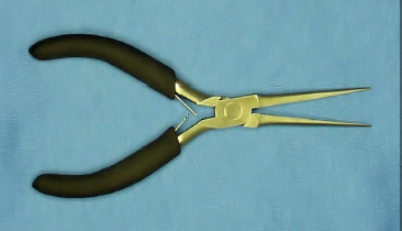
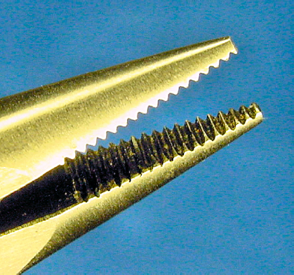
Obtain a pair of smooth (non-serrated/no teeth) jaws for breadboarding, wire bending, and delicate work (see Table 12-6). Because non-serrated jaws are smooth (see Figure 12-24), they don't rip or cut into wire insulation and they can slide under components without damaging them.

Table 12.6. Smooth-Jaw Needle-Nose Pliers
Supplier | Part Number | Price | Description |
|---|---|---|---|
Electronix Express | 0602NNP1 | $1.95 | 6-inch mini needle nose pliers |
Electronix Express | 0602NNP2 | $2.50 | 7-inch mini needle nose pliers |
Micro-Mark | 82827 | $20.95 | 5-inch long needle nose pliers |
Smooth, long, slim, needle-nose pliers are good for removing flat jumper wire from a solderless breadboard (see Figure 12-25). This is especially valuable as the board fills up with wires and components that human fingers can no longer reach.

Serrated (see Figure 12-26) long-nose pliers are better suited for more muscle-intensive work, where a sure grip of the item is important but scraping and scuffing of the item doesn't matter (see Table 12-7).