
In this chapter, you're going to learn about LEDs. You'll see how to select them, test them, and why no self-respecting robot would reject them.
Light Emitting Diodes (LEDs) are modern miracles. They're long lasting, impact resistant, inexpensive, cool to the touch, lightweight, and come in a wide variety of colors and sizes. LEDs are perfectly suited for battery-powered devices due to their low-voltage and low-current requirements.
When pronouncing "LED," speak the letters individually, like "el," "eee," "dee." Don't say it like a word, such as "led."
Because of their usefulness, LEDs are available in different sizes, shapes, colors, and viewing angles. They also have various levels of brightness and efficiency.
The most familiar LED size is T 1 ¾. This terminology comes from the days of miniature incandescent bulbs. The "T" refers to the bullet shape. The 1 ¾ refers to the approximate diameter in 1/8ths of an inch. What an odd standard!
The standard T 1 ¾ size is the least expensive and is available in the widest variety of colors (see Figure 10-1). However, the smaller T 1 size is more modern looking and uses up less space. Surface-mount LEDs are smaller still, but are more difficult for a hobbyist to experiment with.
LEDs are increasingly being advertised by their metric horizontal diameter. For example, a T 1 ¾ LED is often listed as 5 mm (millimeters). Although the T 1 ¾ descriptor implies the shape, the millimeter diameter is more accurate since LEDs are actually manufactured in millimeters, not eighths of an inch.
It won't take long for you to get a feel for LED sizes, since there are only a few common sizes. However, you can always check by using a caliper.
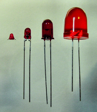
Figure 10.1. LED sizes: surface-mount (1.5 mm), small - T 1 (3 mm), standard - T 1 ¾ (5 mm), and jumbo - T 3 ¼ (10 mm)
A caliper measures small dimensions. The left side of Figure 10-2 shows a T 1 ¾ LED placed in the jaws of the caliper. The digital display reads 5.00 mm. SparkFun Electronics sells a digital caliper for $29.95 (part #TOL-00067). You can also find them on eBay or machining web sites for approximately the same price.

Figure 10.2. Measuring an LED diameter with calipers (left). The other end of the calipers protrudes for measuring the depth of a hole (right).
Although not required equipment, calipers are useful for many tasks in robotic engineering. For example, calipers can measure the thickness of aluminum sheets, the distance between wires on a component, or the depth of a screw hole (see right side of Figure 10-2).
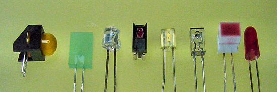
Discrete (individual) LEDs come in a variety of shapes and mounts (see Figure 10-3). The classic bullet shape ("T") still dominates, but side view and square styles are available.
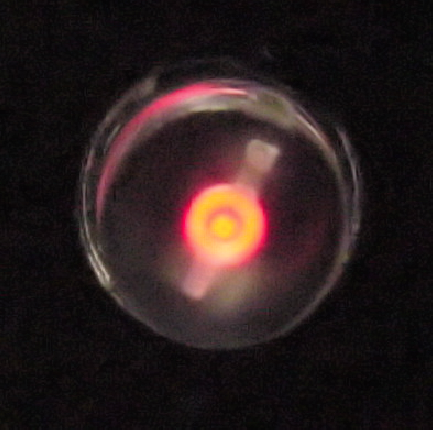
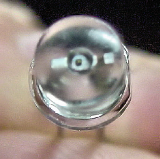
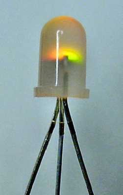
The LED's shape acts as either a collimating lens (light straightening—like a narrow-beam spotlight) or as a light distributor. If you shave down the dome of an ordinary T 1 ¾ LED (use medium-grain sandpaper and then polish with extra fine sandpaper or paste) you'll end up with a peculiar glowing circle instead of a directed beam (see Figure 10-4).
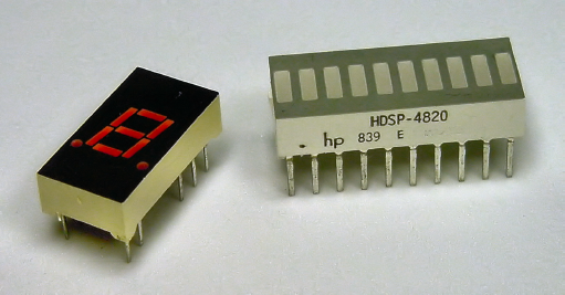
Multiple LEDs are often combined into a group package (see Figure 10-5). A numeric LED (often found in clocks) is nothing more than seven individual LEDs arranged into the number "8." By lighting up specific LEDs, it can form a variety of numbers and letters.
There are three popular lens clarities (see Figure 10-6).
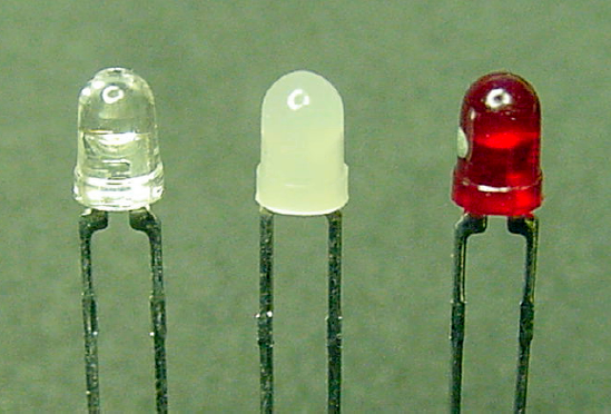
Water-clear LED lenses are sometimes simply called "clear." The lens is a transparent epoxy that tends to bend light unevenly like water. Water-clear LEDs are likely to be a bit brighter since the clear lens itself neither absorbs nor disperses the light. The light output is usually straight ahead like a spotlight.
Water clear is a good choice for an indicator that will be viewed head on but shouldn't be too apparent from the sides. (A traffic light, for example.) Water clear is excellent for a long distance beam, such as an intruder alarm. Sandwich, the line-following robot, uses them because they focus most of their energy on the floor in front of the robot, like headlights.
White-diffused LED lenses are a milky or hazy epoxy. The light spreads out throughout the LED body, making it equally bright and visible from all sides. The amount of "head-on" light is reduced since the semi-opaque lens absorbs some of the light and spreads the light over a larger viewing angle. Because the LED is dim white when off, there's a significant visual difference when the LED lights up with color.
White-diffused lenses are excellent for indicators that need to be visible from the sides as well as the front. Power, ready status, target acquisition, and error lights are good examples.
Color-diffused LED lenses are sometimes called "red diffused" or whatever the particular color. A color-diffused lens spreads light uniformly much the same as a white-diffused lens. Unlike the white lens, the epoxy is tinted so that the LED color is obvious even when the LED is off. This is useful if a bunch of LEDs are adjacent to each other ("Is the red LED turned off?"). However, since the color doesn't change from the off state to the on state (only the brightness), it's more difficult to tell in a bright room if the LED is lit.
Early LEDs were so weak in their light output that they couldn't act as spotlights and couldn't light up a white-diffused lens. As such, colored lenses were the manufacturers' best solution. Colored lenses provided consistent color quality with decent illumination.
Today, colored lenses remain the most common and least expensive. However, with the technological improvements in brightness, the trend is heading toward very lightly tinted water clear and diffused.
It's valuable to know the viewing angle characteristic of a particular LED, as it gives you a sense of how the light beam will spread out. A large viewing angle indicates an LED that is more visible from the sides. Datasheets often show the viewing angle in graph form, which is much more informative than a single number.
Only clear lens LEDs are described with viewing angles, since the color-diffused or white-diffused lenses naturally distribute the light throughout the entire LED.
LEDs became available in commercial production quantities in the 1970s, beginning with the color red. The 1990s marked significant improvements in brightness and efficiency, as well as the introduction of a pure, affordable blue. High-quality white LEDs appeared about that same time because they're really blue LEDs with white-emitting phosphor.
Red, orange, yellow, and yellow-green remain the least expensive. True green, blue, and white are coming down in price, but can still be more expensive than the price of red. Violet and ultraviolet are also available.
LEDs emit most of their light in a narrow band of color. As such, mixed colors like brown would necessitate multiple dies that are finely tuned. That would be a difficult feat to consistently replicate in production quantities. It will be a while before there's a selection of colors resembling a case of crayons ("burnt umber?"). See Figure 10-7 for what's available now.
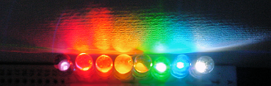
Figure 10.7. A spectrum of colors from infrared to blue, with white on the end. (This image isn't particularly helpful in a grayscale book. But, trust me, it looks lovely.)
In advertisements and datasheets, LED color is often described by a dominant wavelength measured in nanometers (nm). Sometimes this is referred to with the abbreviation λP, for peak wavelength.
When the wavelength of an LED is indicated, use Table 10-1 to see where the color lies within the range. For example, 655 nm is a good red, but 635 nm looms a bit towards orange. (This is fine, if orangish-red is the color you desire.)
Table 10.1. Approximate Color Ranges
Color or Hue | Approximate Wavelength Range |
|---|---|
Infrared (IR) | above 700 nm |
Red | 700 nm to 630 nm |
Orange | 630 nm to 590 nm |
Yellow | 590 nm to 570 nm |
Green | 570 nm to 500 nm |
Blue | 500 nm to 450 nm |
Violet | 450 nm to 390 nm |
Ultraviolet (UV) | Below 390 nm |
Note
Fun If you want to start trouble, assemble some artists, physicists, philosophers, and psychologists into a locked room and ask them "What are the primary colors?" and "What are their wavelengths?"
You can experience the problem for yourself: The next time you see a rainbow, mentally try to slice it into neat chunks of colors. Where does blue end and green begin?
The Commission Internationale de l'Eclairage (CIE) is headquartered in Vienna, Austria. In 1931, the organization published a scientific method for specifying a color based on a standard observer. In their colorimetric system, any color can be described exactly by three values: X, Y, and Z.
Although LEDs are rarely advertised using the CIE system, the specification sometimes appears in datasheets. Instead of absolute XYZ, usually relative x and y chromaticity coordinates are indicated. Software can convert the CIE values to wavelengths or on-screen colors.
LED brightness is often advertised in beam millicandela (mcd). This refers to how intense the light is at a peak angle. To increase a mcd rating, the manufacturer need simply shape the reflector cup and lens to aim the light like a spotlight. More of the light is then concentrated at a narrow angle, making it more intense (brighter).
The mcd rating is barely useful if you really need a bright spot, since you don't know how wide and evenly distributed the bright spot is. Lower-quality LEDs often have a halo shape with a dark hole in the center.
The mcd rating is completely misleading if you're concerned with overall light output. Lumens (lm) is the measurement unit that sums up all of the light, regardless of direction. The manufacturer can't play with lumen numbers by redirecting the light in a single direction because the total light remains the same.
Note
The United States Environmental Protection Agency (EPA) now requires that consumer light bulbs indicate their value in lumens. Unfortunately, this mandate doesn't apply to LEDs.
Lux or footcandle (fc) measurements describe how much light falls in a given area at a given distance away. It doesn't tell you how much total light is coming out of an LED from all sides, nor does it say how evenly distributed the light is.
Efficiency is how much electricity goes in compared to how much light comes out. LEDs are becoming more and more efficient with advances in technology. This is particularly important to battery-powered robots.
For visible light, efficiency is measured in lumens per watt (lm/W). Recall that lumens measures total light output, regardless of direction. Take your total light (lumens) and divide that by your total power (watts) and that tells you how much power was used for each drop of light.
Unfortunately, few manufacturers specify lm/W. This makes it very difficult to tell if a "high-efficiency" LED really is more efficient. However, in most cases, true "high-efficiency" LEDs do illuminate better at lower power levels.
Most LEDs have two wires, called leads (see Figure 10-8). You must connect positive voltage to the anode lead and negative voltage to the cathode lead. An ordinary LED won't light if the leads are connected in reverse. Not only that, but the diode-characteristic of an LED prevents electricity from even passing through it in reverse.
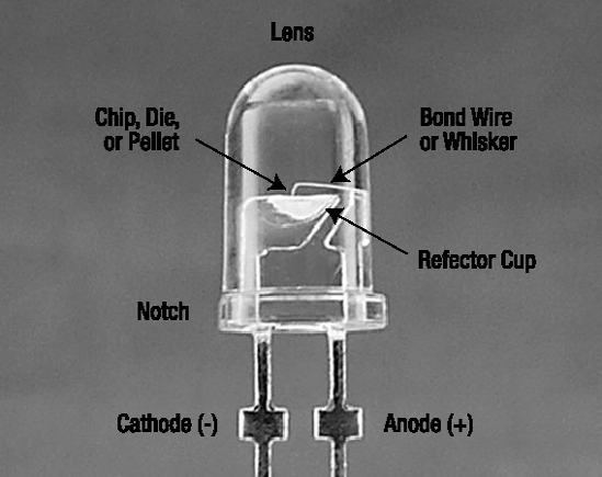
To determine which lead is the cathode, look for a flat or notched side on the bottom of the otherwise round lens. Also, the cathode lead wire is usually shorter than the anode lead wire.
Most often (but not always), the cathode is connected to the side with the reflector cup (see Figure 10-8 and Figure 10-9). The reflector cup is a tiny, rounded mirror that aims light forward.
Inside the reflector cup is a die (see Figure 10-10), also called a chip or pellet. This is the part of the LED that actually emits light. The manufacturer adjusts the chemistry of the die to control the LED's color.

A bond wire (also called a whisker) connects the die to the anode lead. The bond wire is very thin! With some clear LEDs, you can actually see the shadow of that wire (and sometimes the shape of the die) when you aim the LED at the ceiling.
Placing more than one die into an LED allows it to emit more than one color (see Figure 10-11). The lens is usually water-clear or white-diffused, because it wouldn't make much sense to tint the lens with a single color for an LED that can display two or more colors.
Multicolor LEDs are useful for conserving space or for showing multiple statuses. For example: white is off, red is error, green is ready.
Bicolor usually refers to a multicolor LED that has two leads. When the electricity flows in one direction, the LED lights with one color. When the electricity flows in the other direction, the LED lights with the other color.
Since electricity can't flow in opposite directions at the same time, only one color can be lit at a time. However, you can switch the flow back and forth really quickly. To human eyes, the result will be a third color that is a mix of the first two.
Tricolor usually refers to a multicolor LED that has three leads, instead of two (refer back to Figure 10-11). One lead for the first color, another lead for the second color, and a third lead that they share. If they share the cathode (−), it's called common cathode. If they share the anode (+), it's called common anode.
Because one wire is dedicated to each of the two LED colors, they can be enabled at the same time. This permits three colors (one on, the other on, or both on) plus "off."
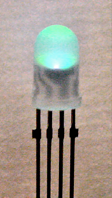
Full-color LEDs are the Holy Grail! These RGB LEDs contain red, green, and blue dies within the same LED. By electrically adjusting the brightness of each die, you can mix the primary colors together to create almost any color.
RGB LEDs have four leads (see Figure 10-12): one lead for red, one lead for green, one lead for blue, and one lead to share. That makes them more complicated to hook up.
In the last ten years, the cost of an RGB LED has dropped to 1/10th the price. You can find them at almost every electronics reseller. For example, SparkFun Electronics sells a 5 mm full color LED for $1.95 (clear lens #COM-00105, diffused lens #COM-09264)
The most obvious way to test an LED is to connect it to a circuit (next chapter) and see if it lights up. However, if your multimeter has a diode test function, you can safely test LEDs and learn a few things about them.
On the multimeter, the black lead should be connected to the COM terminal.
The red lead is usually connected to Ω terminal, but you should check your multimeter's manual.
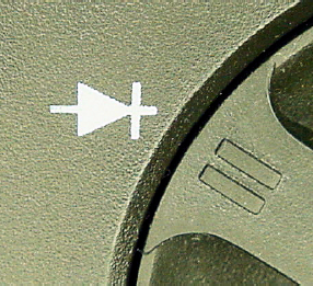
Turn the multimeter dial to the diode symbol, which looks like an arrow crashing into a wall (see Figure 10-13). This indicates a component that allows electricity to flow in one direction (the arrow) but not the other direction (the wall). The diode setting is appropriate for LEDs, because the "D" in "LED" stands for diode.
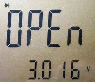
Power up the meter and note what the display indicates. Some meters show "0L" or "OPEN" or something else to indicate that no electricity is currently passing between the probes.
Select an ordinary red LED. The color is important for this test.
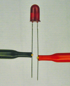
Find the cathode lead of the LED. Usually that's the shorter of the two wires, but check for a flat notch at the bottom of the LED lens to be sure. Connect the black probe to the LED's cathode (−) and connect the red probe to the LED's anode (+) (see Figure 10-14). It's a lot easier if you use hook adaptors on the multimeter test probe tips. Don't worry if you connect the LED in reverse. It's not harmful.
If the multimeter display doesn't change values when the LED is connected, it's likely the LED has been put in backwards (see Figure 10-15). If that's not the problem, double check that all the meter leads are firmly connected to the meter terminals and that the probes are making good contact with the LED leads.
If there isn't a problem with the test setup, it could be that the LED is damaged. It's unlikely that a fresh red LED is going to be broken. However, electrically abused LEDs are likely to have their bond wire melted or some other form of disconnection. In those cases, the LED's internal circuitry is permanently broken open and can't pass power through.
There's also a problem if the meter displays a voltage rating around zero (see Figure 10-16). It is very likely that the LED's anode and cathode leads are accidentally touching each other or that the multimeter test probe's tips are accidentally touching each other.
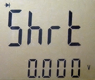
If there isn't a problem with the test setup, it could be that the LED is damaged. A diode voltage value below 400 mV (0.4 V) indicates the power is passing almost directly from the anode to the cathode without passing through the die. This is called a short circuit. It's unlikely that an LED would kick the bucket this way. An open or partially open circuit is more common.
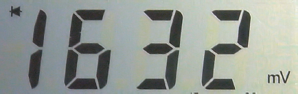
If all goes well, the multimeter will display a red LED's voltage value as being somewhere around 1.6 volts (see Figure 10-17). A lot of meters display this rating in millivolts (mV). For example, 1632 mV is the same as 1.632 V.
Tip
Take a close look at your LED as the multimeter tests it. The LED may be lit up dimly. (You may need to cup your hands around the LED to block the room's lighting.) This is a good trick for proving that the LED is working and also to give you a sense of the LED's efficiency. Poorer-quality LEDs won't light up at all or will have just a glimmer. High-efficiency LEDs will be quite noticeable.
If you haven't already, try reversing the LED leads to see what the meter displays when an LED is hooked up backwards. It should be "open" or "0L." If the LED works in both directions, it's likely a bicolor.
Try a bunch of different kinds of LEDs. You may notice that the physical size of the LED doesn't affect the voltage rating displayed. However, the color does!
Colors nearer to red (including infrared) generally have a lower voltage value and colors nearer to blue have a higher voltage value. In fact, many older or cheaper meters' diode modes usually can't go high enough to test the 2.5 volts required by true green, blue, and white LEDs. That's why I had you start by testing a red LED.
The voltage value displayed on the meter is called the forward voltage drop. That is, if the electricity is moving in the correct direction (forward), then this is how much voltage the LED consumes (drops).
Obviously, voltage usage is valuable information for any component you want to use in your robot. This gives you an idea of minimum battery voltage requirements and how many you can string together for a given battery.
When purchasing LEDs, beware of those listed as having forward voltages (Vf) above 4 V. For example, some blue LEDs are listed at 5 V to 5.5 V. Advanced robot circuits operate at 5 V or lower and many microcontrollers won't guarantee their outputs will always exceed 4.5 V. This makes it impossible to illuminate 5.5 V LEDs without additional circuitry.
Order some assorted packages of LEDs (see Table 10-2). A mixed bulk bag is an inexpensive way to become familiar with sizes, colors, shapes, and lenses. Also, because you may damage some LEDs in your early experiments, it's more comforting to blow a $0.09 red than a $2.99 blue.
Before buying a large quantity of a single kind of LED (as opposed to a variety pack), it's best to begin by ordering only a few of that type to insure the overall light output and quality meet your needs. You'd be surprised how off-color and spotty some LEDs can be.
Table 10.2. LED Assortments
Supplier | Part Number | Price | Number of LEDs |
|---|---|---|---|
Electronic Goldmine | GP27 | $2.49 | 50 assorted (although some surface-mount) |
Electronic Goldmine | GP36 | $2.49 | 15 uniquely shaped assorted |
Jameco | 18041 | $7.95 | 100 standard assorted |
Electronix Express | 32LEDGRAB | $5.90 | 100 variety assorted grab bag |
Electronix Express | 3200LPK | $12.95 | 75 variety assorted |
Electronix Express | 3200LPKD | $19.00 | 105 deluxe assorted |
Sandwich, the line-following robot, lights up with eleven different LEDs (see Figure 10-18). Three green LEDs and three yellow LEDs indicate the brightest path. Three red LEDs sit inside the motor tube to illuminate it from the inside, purely for fun. Two white LEDs act as headlights, for following lines at night or through tunnels.
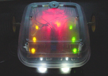
The green, yellow, and red LEDs tend to be inexpensive. In fact, all of the colored LEDs combined cost less than the white LEDs. I could have chosen something other than white to light the path, but it wouldn't have reflected as well off of all possible path colors.
Not only do cool-looking LEDs bring attention to your robot, but also they can be tremendously helpful in diagnosing a problem when used as indicators. It's a good idea to have a bunch lying around.
You've read through ten chapters of the book. Perhaps the battery, alligator clips, resistors, and LEDs provide enough parts to build a circuit? Let's find out.