
Biomass fuels for small and micro combined heat and power (CHP) systems: resources, conversion and applications
Abstract:
Section 5.1 outlines the significance of biomass as a fuel in the world energy supply scene and defines biomass and bioenergy categories. This section also notes the scope and extent of biomass as a renewable energy resource, how it fits in the CO2 cycle and the different types of biomass available. In Section 5.2 the characterisation methods of solid biomass fuels are explained. Section 5.3 goes into detail on the various biomass energy conversion technologies available, of which there are many. Finally, in Section 5.4, having laid the ground concerning the biomass options available for use as an energy resource, current developments in the small- and micro-scale CHP systems are explored and some commercial applications cited.
5.1 Introduction
Because it is expected that conventional fossil fuels such as oil and natural gas will eventually run out, alternatives that provide the usefulness, flexibility and economy of these fossil fuels have been sought for many years. In addition, many scientists, environmentalists, governments and other non-government organisations believe that the accelerated utilisation of fossil fuels over the past decades is the main cause of ‘global warming’ and this forces us to look for cheap and environmentally friendly alternatives to fossil fuels more urgently than ever before (IEA WEO 2009). One of these alternatives is as close as the kitchen waste or the plants outside - ‘biomass’: a source of energy that is both as old as humankind and as new as the morning paper. Biomass resources are increasingly used as alternative fuels for transportation, space heating and power generation because of the persistent high energy prices and pressures on carbon dioxide (CO2) mitigation.
Biomass is a very broad term which is used to describe material of recent biological origin that can be used either as a source of energy or for its chemical components. As such, biomass includes trees, crops and other plants, as well as agricultural and forest residues. Biomass also includes many materials that are considered as waste by society such as food and drink manufacturing effluents, sludges, manures, industrial (organic) by-products and the organic fraction of household waste. In many ways biomass can be considered as a form of stored solar energy. The energy of the sun is ‘captured’ through the process of photosynthesis in growing plants (Klass 2004).
There are a number of common terms related to ‘biomass’, some of which have been misused or misunderstood on occasions and are worth further clarifications here (Klass 2004):
• ‘Bioenergy’: the general term for energy derived from biomass;
• ‘Biofuel’: a solid, gaseous, or liquid fuel produced from biomass;
• ‘Biogas’: a medium-energy-content gaseous fuel, generally containing 40-80 vol% methane, produced from biomass by anaerobic digestion;
• ‘Landfill gas’: a medium-energy-content fuel gas, rich in methane and carbon dioxide produced by landfills that contain municipal solid wastes and other waste biomass;
5.1.1 Biomass – a renewable energy resource
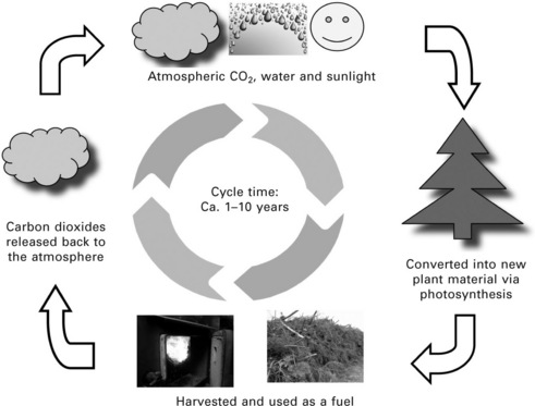
Both burning biomass and burning fossil fuels release carbon dioxide (CO2) to the atmosphere. However, there is a vital difference between the two cases: burning fossil fuels releases CO2 that has been locked up for millions of years in the ground, affecting the natural CO2 cycle and resulting in an increase in the CO2 concentration in the atmosphere. By contrast, burning biomass simply returns to the atmosphere the CO2 that was absorbed as the plants grew over a relatively short period of time (a few years to ca. a decade). The same amount of CO2 which was absorbed from the air via the photosynthesis process while the biomass plant was growing is released back into the air when biomass is burned and there is no net release of CO2 to the atmosphere, i.e. it is CO2-neutral, if the cycle of growth and harvest is sustained. Therefore, biomass can be considered as a renewable energy resource (Fig. 5.1). Some net release of CO2 would take place if the production (planting, harvesting, processing) or transportation of the biomass fuel involved the use of fossil fuels. This part of CO2 can be significant for some biofuels which have low energy ratios (Hoefnagels et al. 2010, Cherubini 2010).
There are many types of biomass and they can be grouped by different methods in different countries. The IEA Bioenergy Education Website on Biomass and Bioenergy (IEA Bioenergy 2010a) groups biomass into categories of woody biomass, non-woody biomass and organic wastes.
Woody biomass mainly includes:
• forest residues, e.g. thinning, pruning or any other leftover plant material after cutting;
• fuel wood, e.g. logs or any other form to be used in small stoves;
• wood waste from wood-processing industry, e.g. bark, sawdust, shavings and offcuts;
• short rotation forestry, e.g. willow, poplar and eucalyptus;
• woodlands/woody urban biomass, e.g. tree trimmings, the green and woody portion of municipal solid waste.
Non-woody biomass mainly includes:
• agricultural crops, e.g. various annual and perennial non-woody energy crops such as Miscanthus, Switchgrass, traditional agricultural crops such as maize/corn, rapeseed, and sunflowers which can be used as animal/human food and liquid biofuels production feedstock;
• crop residues, e.g. rice or coconuts husks, maize cobs and cereal straw;
• processing residues, e.g. bagasse from sugar cane processing and olive marc from olive oil extraction.
5.1.2 Biomass potential to the world energy supply
At the present time, the world is heavily reliant on fossil fuels for energy supply - over 80% of the current annual world energy consumption (~500 Exajoules) comes from coal, petroleum oil and natural gas (EIA IEO 2010). However, the reserves of fossil fuels are finite and subject to depletion as they are consumed - millions of years are required to form fossil fuels in the earth.
Currently, biomass is the fourth largest energy resources after coal, oil and natural gas - the current rate of the world biomass energy consumption is estimated to be in the region of 50 EJ/y which is about 10% of the world total primary energy consumption (IEA Bioenergy 2009). Biomass is the only natural, renewable carbon resource known that is large enough to be used as a substitute for fossil fuels. Some projections have shown that the world’s bioenergy potential seems to be large enough to meet global energy demand in 2050 (Ladanai and Vinterbäck 2009). The annual global primary production of biomass is equivalent to the 4,500 EJ of solar energy captured each year (Ladanai and Vinterbäck 2009) and the rate of energy storage by land biomass is in the order of 3000 EJ/y (Larkin et al. 2004). However, only a small portion of the global energy stored by biomass can be considered as sustainable biomass resources, which is generally believed to be in the region of 250 EJ/y, being equivalent to about 50% of the current global energy consumption (Ladanai and Vinterbäck 2009, European Biomass Industry Association 2010).
The future potential of the global biomass energy depends on many factors, such as land availability and productivity, and the advancement of biomass conversion technologies (Fischer and Schrattenholzer 2001, Hoogwijk et al. 2003, Demirbas et al. 2009, Ladanai and Vinterbäck 2009). But it is reasonable to assume that biomass could sustainably contribute between a quarter and a third of the future global energy mix (IEA Bioenergy 2009).
5.2 Characterisation of solid biomass fuels
Proximate analysis, ultimate analysis and calorific value are commonly used to characterise solid biomass fuels. The proximate analysis serves as a simple means for determining the behaviour of a solid biomass fuel when it is heated. It determines the contents of moisture, volatile matter, ash and fixed carbon of the fuel. On the other hand, the main purpose of an ultimate analysis is to determine the elemental composition of the solid fuel substance. The calorific value of a fuel is a direct measure of the chemical energy stored in the fuel.
Due to the inhomogeneous nature of solid biomass fuels, it is notoriously difficult to prepare small quantities (in the order of grams) of representative samples for biomass characterisation tests. Therefore, strict sampling and preparation procedures specified by the British/European standard BS EN 14778-1:2005 have to be followed by any proximate, ultimate and calorific value tests of solid biomass fuels described below.
5.2.1 Proximate analysis
Since an appreciable amount of water vapour is released when a solid biomass fuel is heated to above the boiling temperature of water, the first parameter of a proximate analysis is the moisture content of the fuel. The moisture content is determined by drying solid biomass samples at 105 °C in air atmosphere until constant mass is achieved and percentage moisture calculated from the loss in mass of the sample. Standard procedures for the determination of moisture content of solid biomass fuels are specified by three British/European standards BS EN 14774-1:2009, BS EN 14774-2:2009 and BS EN 14774-3:2009.
Another major loss occurs when a solid biomass fuel is heated in a covered crucible or in other apparatus which prevents the oxidation of the carbon residue. This loss is referred to as the volatile matter and constitutes the second parameter of the proximate analysis. Volatile matter is determined with the sample being heated out of contact with ambient air at 900 °C for 7 minutes. Standard procedures for the determination of volatile matter of solid biomass fuels are specified by the British/European standard BS EN 15148:2009.
If the remaining residue is further combusted, the residue left after the combustion is called ash, and the weight loss on combustion is referred to as ‘fixed carbon’. Fixed carbon and ash contents constitute the third and fourth parameters of the proximate analysis. This part of proximate analysis, i.e. the combustion of the residue, is carried out in a furnace at 550 °C and the standard procedures are specified by the British/European standard BS EN 14775:2009.
It is not always practical to conduct the above various determinations stepwise. Therefore, one set of samples could be used for the moisture content determination, and another set of samples for the combined moisture and volatile matter loss, and still another set of samples for ash determination.
5.2.2 Ultimate analysis
The main purpose of ultimate analysis is to determine the elemental composition of a solid biomass fuel. The main elements of solid biomass fuels include carbon (C), hydrogen (H), nitrogen (N), sulphur (S) and oxygen (O) but for some solid biomass fuels chlorine (Cl) and other elements may also be of interest. Nowadays, the ultimate analyses of sold biomass fuels are usually carried out with fully automated instruments. The instrumental method for the determination of total carbon, hydrogen and nitrogen contents in solid biomass fuels is described by the British/European standard CEN/TS 15104:2005, whereas the methods for the determination of the total sulphur and total chlorine content in solid biomass fuels are specified by the British/European standard CEN/TS 15289:2006. Sometimes, the determinations of the major elements (Al, Ca, Fe, Mg, P, K, Si, Na and Ti) and the minor elements (As, Cd, Co, Cr, Cu etc.) of solid biomass fuels are also necessary and required. The British/European standards CEN/TS 15290:2006 and CEN/TS15297:2006 describe and specify the corresponding methods and procedures.
5.2.3 Calorific value
The calorific value of a fuel is the number of heat units evolved when unit mass (or unit volume in the case of a gas) of a fuel is completely burned and the combustion products are cooled to 298 K. This definition of calorific value includes the provision that the products of combustion are cooled to 298 K which means the sensible heat and the latent heat of condensation of the water produced during combustion are included in the heat liberated. Therefore, the calorific value of the fuel is designated as ‘ gross calorific value (GCV)’ or ‘high heating values (HHV)’. However, with many industrial applications, the latent heat of condensation is not given up and the total heat liberated per unit mass (or volume) of the fuel is less. The calorific value in the case where the water remains as vapour is designated as ‘net calorific value (NCV)’ or ‘low heating value (LHV)’.
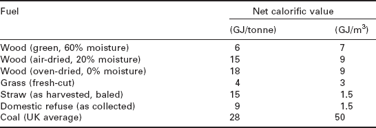
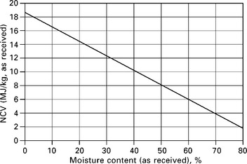
The gross calorific value of a solid biomass fuel is usually determined experimentally by a bomb calorimeter, whereas the net calorific value of the fuel is usually calculated from the gross calorific value and the ultimate analysis of the fuel. Specific experimental procedures and calculation formulae are detailed by the British/European standard BS EN 14918:2009. Many solid biomass fuels contain high moisture content which greatly affects the net calorific value as illustrated by Fig. 5.2 and Table 5.1 (Larkin et al. 2004).
5.2.4 Calculation of analyses to different bases
The analytical data of solid biomass fuels may be reported on different bases including as analysed (air-dried, ad), as-received (ar), dry basis (db) and dry and ash-free (daf). Most analytical values on a particular basis may be converted to any other basis by multiplying it by the appropriate formula given in Table 5.2, after insertion of the numerical values for the symbols. However, for some parameters (H, O and net calorific value) there is a direct involvement of the moisture content. Further details on the calculation of analyses to different bases are described by the British/International standard CEN/TS 15296:2006.
Table 5.2
Formulae for calculation of results to different bases*
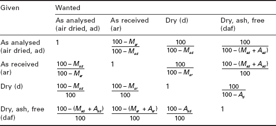
*M - moisture content (%), A - ash content (%)
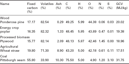
Table 5.3 shows the proximate, ultimate analyses and gross calorific values of selected solid biomass fuels (Gaur and Reed 1995). The proximate and ultimate analyses of more solid biomass fuels can be found in many references such as Gaur and Reed (1995), Annalmalai and Puri (2007), and biomass databases such as Phyllis (2010).
Table 5.3
Proximate, ultimate analyses and gross calorific values of selected solid biomass fuels (dry basis) (Gaur and Reed 1995)
5.3 Biomass conversion technologies
Most biomass materials are initially solid, bulky and expensive to transport over appreciable distances. They often contain high moisture content and decompose rather quickly, so few of them are good long-term energy stores. If biomass fuels are to compete with our present fossil fuels, they must be able to meet the demand for appropriate forms of energy at competitive prices. The most important criteria for new forms of energy are their availability and transportability. The premium fossil fuels - oil and natural gas - are valued because their energy can be stored with little loss and made available where and when we need it.
Biomass energy conversion technologies can be classified in terms of either the conversion process they use or their end product. The following biomass conversion processes will be briefly discussed:
5.3.1 Combustion of solid biomass fuels
Direct combustion is the most common way of converting biomass to energy - both heat and electricity - and worldwide it already provides over 90% of the energy generated from biomass (Van Loo and Koppejan 2007). Direct combustion of solid biomass fuels is well understood, relatively straightforward, commercially available, and can be regarded as a proven technology. Biomass combustion systems can be easily integrated with existing infrastructure. In theory, it is possible to burn any type of biomass but in practice combustion is feasible only for biomass with moisture content of lower than ca. 50% (Goyal et al. 2008).
Combustion of a solid biomass fuel can be characterised by a three-stage process (Fig. 5.3). The first stage is drying, i.e. the evaporation of any water in the fuel. This stage does not produce energy but consumes energy. Then in the combustion process itself, there are two further stages: the volatile release (devolatisation) and combustion stage - the volatile matter is released as a mixture of vapours (CO, CO2, H2, H2O, CxHy, etc.) as the temperature of the fuel rises, the combustion of volatile matter produces the flame seen around the burning solid fuel; and the char combustion stage - the solid which remains consists of char together with any inert matter and the char (mainly carbon) burns to produce CO2, whilst the inert matter becomes clinker, slag or bottom ash.
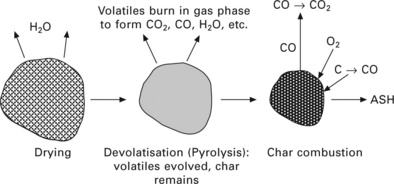
A feature of solid biomass fuels is that three-quarters or more of their energy is in the volatile matter (unlike coal, where the fraction is usually less than half). The design of any biomass combustion facility should ensure that the volatile matter of the fuel is burnt to completion. The heterogeneous chemical reactions of biomass char with oxygen from air are also important - the char combustion stage is the slowest of the three stages described above. To achieve overall high combustion efficiency, a sufficient combustion time has to be provided for the char combustion stage.
Most solid biomass materials can be burnt to produce heat for use in situ or at not too great a distance. However, simple physical processing, involving sorting, chipping, compressing, air-drying, etc., is usually necessary for most solid biomass materials to be used in efficient combustion processes. Some raw solid biomass materials require further pre-treatment before they can be used in conventional combustion plants. For example, household waste, as collected, is not an ideal fuel for combustion because of its variable contents, high moisture content and low calorific value. But it can be burned in specially designed MSW (municipal solid waste) combustion (incineration) plants or converted to RDF (refuse-derived fuel) or d-RDF (densified refuse-derived fuel) to be burned alone or co-fired with coal in conventional combustion plants (Larkin et al. 2004).
Modern systems for burning solid biomass fuels are as varied as the solid biomass fuels themselves, ranging in size from small stoves through domestic space and water heating systems to large boilers producing megawatts of heat and/or electricity (Figs 5.4 and 5.5). Van Loo and Koppejan (2007) provide a comprehensive review of biomass combustion basic principles and industrial applications and therefore it is an indispensible reference for biomass combustion researchers and practitioners.
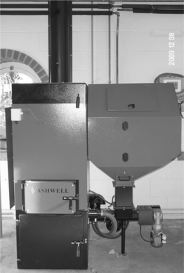
5.4 A 50 kW wood pellet boiler installed at the Department of Architecture and Built Environment, University of Nottingham, UK.

Biomass combustion produces a range of pollutants including carbon monoxide, nitrogen oxides, particulates, smoke, etc., and can have potential operational problems whether burning in dedicated combustion plants or co-firing with coal (Demirbas 2005, Van Loo and Koppejan 2007, Khan et al. 2009, H. Liu et al. 2010a). However, biomass combustion can be CO2- neutral if the cycle of biomass growth and harvest is sustained.
5.3.2 Biomass gasification
Thermochemical gasification is the conversion by partial oxidation at elevated temperature of a carbonaceous feedstock such as biomass into a gaseous energy carrier (Liu and Neubauer 2010). This gas contains carbon monoxide, carbon dioxide, hydrogen, methane, higher hydrocarbons such as ethane and ethene, water, nitrogen (if air is used as the oxidising agent) and various contaminants such as small char particles, ash, tars and oils. The partial oxidation can be carried out using air, oxygen, steam or a mixture of them.
Air is a cheap and widely used gasification agent but air gasification of biomass produces a low calorific value gas (ca. 3-6 MJ/Nm3) which is suitable for boiler, engine and turbine operation but not for pipeline transportation due to its low energy density (Wang et al. 2008). Oxygen gasification of biomass produces a medium calorific value gas (ca. 10-15 MJ/m3) suitable for limited pipeline distribution and as synthesis gas for conversion, for example, to methanol and gasoline. Such a medium calorific value gas can also be produced by steam gasification.
Gasification is not a new process and has been around for over a century (BEF 2010, Liu and Neubauer 2010). ‘Coal gas’, the product of coal gasification, was widely used in the UK and elsewhere for many decades. ‘Wood gas’, the product of wood gasification, was used for heating, lighting and even as vehicle fuel. Both ‘coal gas’ and ‘wood gas’ were gradually superseded by natural gas from around 1930. But during the Second World War, over a million biomass gasifiers were built for the civilian sector while the military used up all the gasoline. The oil crisis of the 1970s also sparked a renewed interest in biomass gasification systems all over the world (BEF 2010).
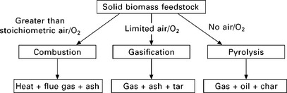
There are many different designs of gasifiers (Basu 2010), but with the same set of main gasification reactions: those of hot steam and oxygen interacting with the solid fuel (Liu and Neubauer 2010). The gasification reactions can only proceed at elevated temperatures (a few hundred to over a thousand degrees Celsius) and pressures (from a little above atmospheric pressure to 30 times this). Similar to the combustion stages shown in Fig. 5.3 the gasification process begins with the drying of the solid fuel to evaporate moisture, followed by the release of the volatiles from the heated solid, leaving the char. Volatiles and char in turn undergo partial oxidation reactions with steam and oxygen, resulting in the combustible gas. Figure 5.6 compares the three thermochemical conversion processes of biomass: combustion, gasification and pyrolysis.
Although biomass gasification has been practised for over 100 years, so far it has had a very limited commercial impact on the energy market due to competition from other fuel sources and other energy forms. The past decade has seen a major resurgence of interest in biomass gasification processes mostly due to environmental and political pressures required of CO2 mitigation measures. Very few biomass gasification processes have proved economically viable, although the technology has progressed steadily. However, there is sufficient expertise and knowledge now available to have a high level of confidence in modern gasification processes. Small gasification plants (< 300 kW) are now available commercially, often combined with gas engines driving small generators, and demonstration plants in the range 10-30 MW have been in operation since the mid-1990s (Reed and Gaur 2001, Knoef 2005, Wu et al. 2008, Liu and Neubauer 2010, Alauddin et al. 2010). The overall conversion efficiency from the energy of the solid biomass fuel to that of the resulting gas varies widely, from as little as 40% in relatively simple systems, to 70% or more in the most sophisticated plants (Liu and Neubauer 2010).
5.3.3 Biomass pyrolysis
Pyrolysis is the thermal decomposition occurring in the absence of oxygen, and it is also the initial step in combustion and gasification processes where it is followed by total or partial oxidation of the primary products. For many centuries, charcoal has been produced by pyrolysis of wood. The process of charcoal making involves slowly heating wood in the near absence of air, typically at 300-500 °C, until the volatile matter has been driven off. The residue is the charcoal - a fuel which has about twice the energy density of the original and burns at a much higher temperature. Depending on the moisture content and the efficiency of the process, 4-10 tonnes of wood are required to produce one tonne of charcoal, and if no attempt is made to collect the volatile matter, up to three-quarters of the original energy content can be lost (Larkin et al. 2004). Today this conventional pyrolysis process to produce charcoal is termed as ‘slow pyrolysis’. Slow pyrolysis of biomass leads to less liquid and gaseous product and greater char production (Goyal et al. 2008).
The term pyrolysis is now normally applied to the processes where the aim is to collect the volatile components and condense them to produce a liquid fuel or bio-oil. Bio-oil is composed of a very complex mixture of oxygenated hydrocarbons, and like crude fossil oil can be used for heat production, power generation and synthesis gas production as well as the production of a range of chemicals (Mohan et al. 2006, Goyal et al. 2008). Bio-oil can also be upgraded to transportation fuels (Balat et al. 2009). The main benefit of the pyrolysis process, when compared to combustion and gasification, is that a liquid fuel is easier to transport than either solid or gaseous fuels (Goyal et al. 2008). This means that the pyrolysis plant does not have to be located near the end-use point of the bio-oil, but can instead be located near the biomass resource supply, which results in considerably lower fuel transportation costs. High transportation costs are one of the limiting factors for the construction of large-scale biomass power plants, which have higher efficiencies and lower emissions than small-scale plants.
The pyrolysis reaction is relatively complex and results in non-equilibrium products, making their properties hard to predict. The products and their properties are dependent on the process temperature, the period of heating, ambient conditions, the presence of oxygen, water and other gases, and the nature of the feedstock. In general, lower process temperature and longer heating periods result in the production of charcoal, high temperature and longer heating periods increase the biomass conversion to gas, and moderate temperature and short heating periods are optimum for producing liquids (Bridgwater et al. 1999, IEA Bioenergy 2010a, 2010b). Figure 5.7 shows a widely accepted simplified model of the principal pyrolysis pathways (Bridgwater et al. 1999).
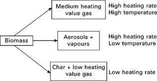
5.7 Biomass pyrolysis pathways (Bridgwater et al. 1999).
Current trends in the research and development of pyrolysis are focused on the so-called ‘ fast pyrolysis’. Fast pyrolysis is a thermal decomposition process that occurs in the absence of oxygen, at moderate temperatures with a high heat transfer rate to the biomass particles and a short hot vapour residence time (in the order of a few seconds) in the reaction zone. In fast pyrolysis biomass decomposes to generate mostly vapours and aerosols and some charcoal. After cooling and condensation, a dark brown mobile liquid is formed which has a heating value about half that of conventional fuel oil. The essential features of a fast pyrolysis process for producing liquids are (Bridgwater et al. 1999):
• very high heating and heat transfer rates at the reaction interface, which usually requires a finely ground biomass feed;
• carefully controlled pyrolysis reaction temperature of around 500 °C and vapour phase temperature of 400-450 °C;
• short vapour residence times of typically less than 2 seconds; rapid cooling of the pyrolysis vapours leads to the bio-oil product;
• the main product, bio-oil, is obtained in yields of up to 75 wt% on dry feed basis, together with by-products, char and gas, which are used within the process to provide the process heat requirements so there are no waste streams other than the flue gas and ash.
In comparison with combustion and gasification, biomass pyrolysis is in the early state of development. Although biomass fast pyrolysis technologies for liquid fuel production have been successfully demonstrated at small scale, and several large pilot plants or demonstration projects (up to 200 ton/day biomass feed design capacity) are in operation or at an advanced stage of construction, they are still relatively expensive compared to fossil-fuel-based energy technologies and thus face economic and other non-technical barriers when trying to penetrate the energy markets (IEA Bioenergy 2010b).
5.3.4 Biomass fermentation to produce ethanol
Fermentation is an anaerobic biological process in which sugars (e.g. C6H12O6) are converted to alcohol by the action of micro-organisms, usually yeast. The required product, ethanol (C2H5OH) is separated from other components by distillation. Figure 5.8 shows the block diagram of the basic steps involved with biomass fermentation (DOE 2010).
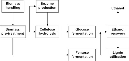
5.8 Basic steps of biomass fermentation (DOE 2010).
Fermentation requires sugar, so the obvious source is sugar-cane. Brazil’s PRO ALCOOL programme - producing ethanol from sugar residues - was the world’s largest commercial biomass programme in the twentieth century (Larkin et al. 2004). Plants whose main carbohydrate is starch (for example, potatoes, corn and wheat) require initial processing to convert the starch to sugar. This route is followed in the US where the main feedstock is corn. The US ethanol industry relies almost exclusively on corn, consuming 20% of the available corn supply in 2006 (EIA ISA-Biomass 2010). Other types of plant matter, called cellulosic biomass and made up of very complex sugar polymers, are under research and development as a feedstock for bioethanol production. Specific feedstocks of cellulosic biomass currently under research and development for bio-ethanol production include: agricultural residues, forestry wastes, municipal solid waste, food processing and other industrial wastes, and energy crops. The main components of these types of biomass are 40-60 wt% of cellulose, 20-40 wt% of semi-cellulose and 10-24% of lignin, depending on the biomass sources. The lignin part remains as residual material after the sugars in the biomass have been converted to ethanol. It contains a lot of energy and can be burned to produce steam and/or electricity for the biomass-to-ethanol process. Despite various efforts to develop cellulosic ethanol in many parts of the world, further significant progress in terms of both technologies and energy policies are needed to commercialise and make cellulosic ethanol a viable economic option in the future (EIA ISA-Biomass 2010, Gnansounou and Dauriat 2010, Talebnia et al. 2010, Binod et al. 2010, Fang et al. 2010, Gnansounou 2010, Alvira et al. 2010).
The liquid resulting from fermentation contains about 10% ethanol, which is distilled off. The heating value of bio-ethanol is about 27 MJ/kg, which is about 70% of the heating value of normal petrol (~40 MJ/kg). Unlike methanol, ethanol cannot simply substitute for petrol, but it can be used as a gasoline extender in gasohol which is a mixture of petrol (gasoline) and ethanol. A few years ago, cars without engine modification could use the gasohol containing ethanol up to 26%. But now many cars have been equipped to enable them to run on E85, a mixture of 85% ethanol and 15% gasoline (WhatGreenCar 2010). With suitable engine modifications (retuning, etc.), ethanol can also be used directly.
A complete process of fermentation requires a considerable heat input but this can usually be supplied by biomass residues. The conversion efficiency of fermentation is low, but the technology is comparatively simple and the plant cost is low. When the inputs are residues or surpluses and the output is a desirable product, low efficiency of fermentation may be a price worth paying (Larkin et al. 2004). Ethanol production from biomass fermentation has been commercially available for over a decade and widely practised all over the world (Nigam and Singh 2011). World production of ethanol increased from ca. 37 billion litres in 2005 to 73.9 billion litres in 2009 (Bioethanol 2010). The world’s top five bioethanol producers in 2009 were:
• USA – 40 130 million litres (ca. 54% of the world total)
• Brazil – 24 900 million litres (ca. 34% of the world total)
• China – 2050 million litres (ca. 3% of the world total)
However, present world-wide bio-ethanol production relies heavily on food crops such as corn, grain and sugarcane, but the limited supply of these crops can lead to competition between their use in bio-ethanol production and food provision. Cellulosic biomass is the most promising feedstock considering its great availability and low cost, but the large-scale production of bio-ethanol from cellulosic feedstock is yet to be demonstrated and commercialised (Balat 2011, Nigam and Singh 2011).
5.3.5 Anaerobic digestion
Anaerobic digestion, like pyrolysis, occurs in the absence of air; but in this case the decomposition is caused by bacterial action rather than high temperatures. It is a biochemical process which takes place in almost any biological material, but is favoured by warm, wet and airless conditions. It occurs naturally in decaying vegetation on the bottom of ponds, producing the marsh gas which bubbles to the surface and can catch fire. It also occurs in landfill sites of municipal solid wastes and purpose-built anaerobic digesters of wet wastes. Landfill gas is produced in a landfill site due to anaerobic digestion taking place over a period of years. The landfill site itself acts as the digester and the operator has very limited control of the digestion process (Larkin et al. 2004). The gas generated in purpose-built anaerobic digesters of wastes is specifically termed as ‘biogas’ which is a result of anaerobic digestion of wastes taking place over a period of days to weeks in the digesters. With the purpose-built digesters, the anaerobic digestion process can be carefully controlled by the operation temperature of the digester (Larkin et al. 2004). Both landfill gas and biogas contain a mixture of mainly methane and carbon dioxide and can be used to produce heat or electric power, or in many cases both. Biogas can also be upgraded as transport fuel as demonstrated in Switzerland and Sweden (Börjesson and Mattiasson 2007, Poeschl et al. 2010).
The basic steps of anaerobic digestion are illustrated in Fig. 5.9 (Appels et al. 2008). Despite the successive steps, the hydrolysis step, which degrades both insoluble organic material and high molecular weight compounds such as lipids, polysaccharides, proteins and nucleic acids, into soluble organic substances (e.g. amino acids and fatty acids), is generally considered as the rate limiting step. The overall rate of digestion, the composition of the final gas and residuals are affected by various parameters including pH, alkalinity, temperature, retention times and the design of the digester as well as the nature of the feedstock (Appels et al. 2008, Ward et al. 2008).
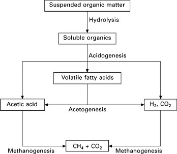
5.9 Basic steps in the anaerobic digestion process (Appels et al. 2008).
Wet biomass wastes, such as dung and sewage, are especially well suited for the anaerobic digestion process. However, some organic materials, such as lignin, cannot be effectively digested by the anaerobic digestion process. Therefore, woody biomass wastes which contain a significant amount of lignin should not be used in an anaerobic digester - gasification is a better option to convert woody biomass to a gaseous fuel. The advantages of anaerobic digestion when compared to thermochemical processes are that as a by-product it also produces a concentrated nitrogen fertiliser, and serves as a means of waste neutralisation, which would otherwise be dumped in the environment. Because of this, small-scale digesters are well suited for integration in small rural farms, and have been used extensively in several developing countries like China (Jiang et al. 2007) and India (Rao et al. 2010).
The technology of using anaerobic digestion to produce biogas is well developed and the last decade has brought about huge steps forward, in terms of maturation of biogas technologies and economic sustainability for both small- and large-scale biogas plants (Holm-Nielsen et al. 2009). Now there are a range of digesters commercially available. However, the capital cost of a digester may be out of reach for a typical small farmer in some developing countries (Larkin et al. 2004). Nevertheless, there is considerable potential for biogas production from anaerobic digestion in Europe, as well as in many other parts of the world (Holm-Nielsen et al. 2009, Jiang et al. 2007, Rao et al. 2010).
5.3.6 Biodiesel production
Biodiesel production from oilseed crops such as soya, rapeseed, sunflower, corn, etc., involves chemical and/or physical processes. The first step of biodiesel production from oilseed crops is to produce vegetable oils from the feedstock and the second step is to produce the biodiesel from the vegetable oils. The direct use of vegetable oils as fuel in compression ignition engines is problematic due to their high viscosity (about 11-17 times greater than petroleum diesel fuel) and low volatility (Atadashi et al. 2010). Vegetable oils do not burn completely and form carbon deposits in the fuel injectors of diesel engines and therefore conversion of the vegetable oils to biodiesel is preferred.
There are two main processes for extracting oil from biomass seed feedstock: mechanical press extraction and solvent extraction. In mechanical press extraction, the oil seed feedstock is first heated to about 40-50 °C. The oil seed is then crushed manually or automatically (e.g. in a screw press). After most of the oil is removed, the remaining seed meal can be used as an animal feed. The solvent process extracts more of the oil contained in the oil seed feedstock but requires more costly equipment. The process uses a solvent (most commonly hexane) to dissolve the oil. After extraction, a distillation process separates the oil from the solvent. The solvent condenses and can be recycled and reused in the process. Solvent extraction produces vegetable oil with a higher degree of purity than the mechanical press process.
Several methods are available for producing biodiesel from vegetable oils but currently the method of choice is a chemical process, called ‘transesterification’ (Ma and Hanna 1999, Singh and Singh 2010). The main purpose of the transesterification process is to lower the viscosity of the oil. In the transesterification process, vegetable oil reacts with an alcohol (methanol or ethanol), usually in the presence of a catalyst, and reduces its viscosity, resulting in a higher quality fuel, biodiesel.
Biodiesel can also be produced from recycled oil or fat (Enweremadu and Mbarawa 2009). It is estimated that about half of the biodiesel industry can use recycled oil or fat. Biodiesel production from waste oils from chip shops is already a reality in the UK. Argent Energy (UK) Limited operates the UK’s first large-scale biodiesel plant which started the production of biodiesel in March 2005 using recycling tallow and used cooking oil (Argent Energy Limited 2010).
The energy content of biodiesel is 10-12% lower than petroleum diesel (~38 GJ/tonne vs. ~42 GJ/tonne). Biodiesel has many advantages, including (EBB 2010):
• It is non-toxic and biodegradable.
• it reduces the emission of harmful pollutants from diesel engines.
• It has a high cetane number (above 100, compared to only 40 for diesel fuel). Cetane number is a measure of a fuel’s ignition quality. The high cetane numbers of biodiesel contribute to easy cold starting and low idle noise.
• Blends of 20% biodiesel with 80% petroleum diesel can be used in unmodified diesel engines. Biodiesel can also be used in its pure form but may require certain engine modifications to avoid maintenance and performance problems.
• The use of biodiesel can extend the life of diesel engines because it is more lubricating and, furthermore, power output is relatively unaffected by biodiesel.
• Biodiesel replaces the exhaust odour of petroleum diesel with a more pleasant smell of popcorn or French fries.
Biodiesel production has increased dramatically over the past few years. Biodiesel is now widely available in many countries. The top five biodiesel producers in 2009 were (Biodiesel 2010):
5.4 Current development of small and micro scale biomass combined heat and power (CHP) technologies
Biomass is best suited for decentralized, small-scale and micro-scale combined heat and power (CHP) systems* due to its intrinsic properties, in particular its low calorific values in comparison with fossil fuels (Table 5.1). On one hand, small-scale and micro-scale biomass CHP systems can reduce transportation costs of biomass and provide heat and power where they are needed. On the other hand, it is more difficult to find an end-user for a great amount of heat produced in larger CHP systems (Eriksson et al. 2007). Over the past decade or so, the development of small-scale and micro-scale biomass- fuelled CHP systems has been carried out by many researchers all over the world. Dong et al. (2009) have provided a review of small- and micro-scale biomass CHP technologies; in particular, those based on organic Rankine cycle (ORC) power generation. Despite various research efforts, small- and micro-scale biomass CHP systems still suffer from undesirable economics and technical uncertainties which require considerable technical advances in the future. With the expected continued rise in gas and electricity prices and the advances in the development of biomass conversion technologies and biomass fuel supply infrastructure, biomass-fuelled CHP systems can only become more economically competitive.
5.4.1 Introduction of biomass CHP technologies
Biomass CHP technologies can be grouped in different ways such as by the biomass conversion technology or by the prime mover. In this chapter, they are grouped by the biomass conversion technology.
Various combinations of biomass conversion technologies and prime movers have been used with biomass-fuelled CHP systems as shown in Table 5.4. The biomass conversion technologies, namely combustion, gasification, pyrolysis, fermentation, anaerobic digestion and biodiesel production were discussed in the Section 5.3, whereas the prime movers, namely steam turbines, steam engines, Stirling engines, organic Rankine cycle turbines, gas turbines and internal combustion engines, are characterised in other chapters of this book, and therefore, the following discussion on the biomass CHP technologies will focus only on the specific features of the combinations of the biomass conversion technologies and the prime movers.
Table 5.4
| Biomass conversion technology | Prime mover |
| Combustion | Steam engine; Steam turbine; Stirling engine; Organic Rankine cycle (ORC) turbine; Hot air gas turbine |
| Gasification | Steam turbine; Internal combustion engine; Gas turbine/micro-turbine; Fuel cell |
| Pyrolysis | Internal combustion engine |
| Biochemical/biological processes (fermentation and anaerobic digestion) | Internal combustion engine |
| Chemical/mechanical processes (biodiesel production) | Internal combustion engine |
(modified from Dong et al. 2009)
5.4.2 Combustion-based biomass CHP technologies
Combustion-based biomass CHP technologies are the dominant ones that are used from large-scale power plants to micro-scale CHP systems. The heat released from biomass combustion is used to produce steam, hot air or organic working fluid vapour which can drive a steam turbine, a steam engine, a hot air gas turbine or an ORC turbine to generate electricity.
Biomass conversion technology: combustion and prime mover - steam turbine/steam engine
Of all the technologies listed in Table 5.4, ‘combustion’ and ‘steam turbine’ are the most widely used combination, particularly for large-scale and medium-scale biomass-fuelled CHP systems (Masters 2004). Indeed, the majority of current world biomass power plants are based on ‘combustion’ and ‘conventional steam turbine Rankine cycle’ (Masters 2004). Steven’s Croft Biomass Power Station in Scotland (rated 44 MWe) of E.ON, which started its commercial operation in 2007, is a good example of a dedicated biomass power plant based on the technologies of ‘combustion’ and ‘steam turbine’ (E.ON 2010). The Markinch Biomass CHP plant in Scotland (rated 50 MWe) of RWE is another example of the application of the technologies, which is under construction and scheduled to start operation in 2012 (RWE 2010). The prohibitive cost of transporting dispersed and bulky biomass feedstock over long distance often limits the capacity of this type of biomass power/CHP plants to the order of 100 MWe, which results in the power generation efficiency to be in the region of 20%. If the same technologies were applied to small- and micro-scale biomass CHP systems, it would lead to both unacceptable low power generation efficiency and high capital costs (Pritchard 2002). The minimum capacity of biomass-fired steam turbine CHP is likely to be around 2 MWe, whereas for biomass-fired steam engine CHP it is likely to be around 200 kWe (BIOS 2010a, 2010b).
Biomass conversion technology: combustion and prime mover - ORC turbine
The combination of ‘combustion’ and ‘ORC turbine’ is receiving more and more attention in the development of small- and micro-scale biomass CHP systems. Instead of water, ORC uses organic chemicals with favourable thermodynamic properties as working fluids. Further details of ORC are discussed in Chapter 9. Despite the fact that ORC is linked with low electrical efficiency which is likely to be in the region of 6-17% for small- and micro-scale power/CHP systems, new applications of ORC are consistently explored due to its possibility to utilise the low-level waste heat from other processes (Schuster et al. 2009). The organic working fluid evaporates at lower temperatures than water and therefore ORC CHP systems can work at lower temperatures and pressures than the conventional steam Rankine cycle (Dong et al. 2009). For this reason, ORC is particularly suitable for small-scale and micro-scale biomass-fired CHP systems.
Biomass-fired ORC-based CHP plants with capacity higher than 200 kWe have been demonstrated and in operation across Europe for almost a decade (Dong et al. 2009). Two particular demonstration plants are worth mentioning: the 400 kWe Admont CHP plant and the 1000 kWe Lienz biomass CHP plant (Admont 2001, Obernberger et al. 2002, BIOS 2010c). For both ORC- based biomass CHP demonstration plants, the biomass combustion furnace/thermal oil boiler and the ORC process were coupled by a thermal oil cycle, whereas silicon oil was selected as the organic working fluid (Fig. 5.10).
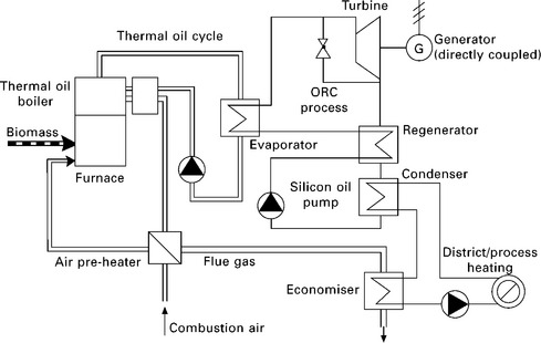
5.10 Schematic of the ORC-based biomass CHP plant of Lien (Obernberger et al. 2002, BIOS 2010c).
The condensation of the silicon oil takes place at a temperature level that allows the heat recovered to be utilised with the hot water feed temperature of about 80-90 °C. The net electric efficiency of the Admont CHP plant was reported to be 7.4% for year 2000 but was expected to increase to 10-11% soon afterwards (Admont 2001). The net electric efficiency of the 1000 kWe Lienz biomass CHP plant amounted to 18% at nominal load and about 16.5% at 50% partial load at feed water temperatures of 85 °C (Obernberger et al. 2002). This underlines the excellent partial load behaviour of the technologies, which is especially relevant for heat-controlled operation of a CHP plant. Some manufacturers of ORC plants now offer commercial products of biomass-fired ORC-based CHP plants with capacity in the range of ca. 200 kWe and 2000 kWe. For example, Turboden (2010) has had 139 biomass-fired ORC-based CHP plants built or under construction in 15 countries by 20 September 2010 - these plants are within the size range of 200-2200 kWe. Turboden actually manufactured and supplied the ORC of the Lienz biomass CHP plant (Obernberger et al. 2002).
The development of micro-scale biomass ORC-based CHP systems has received more and more attention over the last few years, partly due to the increasing demand for the building applications of micro-scale CHP systems. H. Liu et al. (2010b) have developed a micro-scale biomass ORC-based CHP system at the University of Nottingham in the UK. The main components of the CHP system, schematically shown in Fig. 5.11, include a pellet biomass boiler, a hot water cycle and an organic Rankine cycle. Due to safety concerns with the potential users of micro-scale CHP systems, the biomass boiler and the organic Rankine cycle are coupled with a hot water cycle, instead of a thermal oil cycle (Fig. 5.10) which is normally used for larger biomass ORC-based CHP systems such as those developed by Turboden (2010). Two hydrofluoroethers (HFEs), HFE 7000 and HFE 7100, which are environmentally friendly with non-ozone depletion and low global warming potentials, have been tested as the ORC working fluid. The latest experimental results have proved the feasibility of the CHP system, produced 0.8 kW of electricity, and achieved ca. 2% of electric power generation efficiency and 88% of overall CHP efficiency. Further improvement of the CHP system and its main components, in particular the ORC turbine, is under way and better electric power generation efficiency is expected in the future.
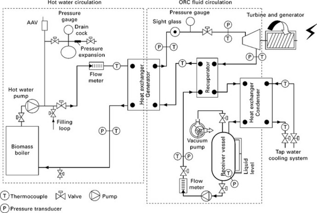
5.11 Schematic of biomass-fired micro-scale CHP system with ORC developed at the University of Nottingham, UK (H. Liu et al. 2010b).
The selection and optimisation of the ORC turbines is of considerable importance to the development of micro-scale biomass-fired ORC-based CHP systems as ORC turbines greatly affect the organic Rankine cycle efficiency and electric power generation efficiency of the CHP systems. However, at the present time, micro-scale turbines for organic fluids with capacity smaller than 10 kWe are not commercially available and many researchers have to use replacement turbines with their micro-scale ORC-based CHP systems (Qiu et al. 2010). Scroll expanders are one of the popular choices for the replacement micro-scale ORC turbines (Peterson et al. 2008, Wang et al. 2009, Lemort et al. 2009, Quoilin et al. 2010, G. Liu et al. 2010), whereas modified air motors were used by H. Liu et al. (2010b) and Qiu et al. (2010). Further technical and economic advances on ORC turbines are needed before micro-scale ORC-based CHP systems can be commercialised.
Biomass conversion technology: combustion and prime mover - Stirling engine
Stirling engine-based small- and micro-scale biomass CHP systems have been researched for more than a decade. Podesser (1999) reported the laboratory testing results of a biomass Stirling engine with air (nitrogen) as working gas and a shaft power of 3 kW. Biomass Stirling engine CHP systems rated 35 kWe and 70 kWe had been developed and demonstrated by researchers in Austria and Denmark (Obernberger et al. 2003, Biedermann et al. 2004, BIOS 2010d). A 35 kWe plant was put into operation in 2002 and was successfully tested for more than 10 000 hours, and a 70 kWe plant has been in operation since autumn 2003 (BIOS 2010d). The overall electrical efficiency and the overall CHP efficiency of the 35 kWe and 70 kWe plants were reported to be 11.7% and 88.3%, respectively (BIOS 2010c). A field test with seven 35 kWel plants has been initiated and the first demonstration plants were put into operation in summer 2005 (BIOS 2010d). Although the demonstrated biomass Stirling engine CHP system is ‘not available on the market at the moment’, it is claimed that the CHP system ‘will be commercially available within the next few years’ (BIOS 2010d). Figure 5.12 shows the schematic of the small-scale biomass Stirling engine CHP system (BIOS 2010d).
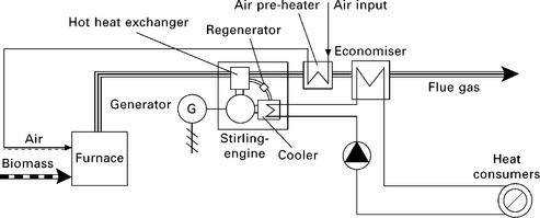
5.12 Schematic of the small-scale biomass Stirling engine CHP of BIOS (2010d).
A US company, Sunpower (Sunpower 2010) started their research and development into micro-scale Stirling engine-based biomass CHP systems in the 1990s and tested units as small as 1 kWe. Sunpower (2010) specialises in the development and delivery of a variety of free-piston Stirling engines at power levels ranging from 35 We to 7.5 kWe which have now been demonstrated by using a variety of heat inputs including biomass, liquid and gaseous fossil fuel burners, solar concentrators and heat pipes. A German company (Sunmachine 2010) is commercialising its Stirling engine-based biomass CHP systems - ‘SUNMACHINE® Pellet’ which is rated 1.5-3.0 kWe. Recently, a SUNMACHINE® Pellet CHP system was tested in laboratories by Thiers et al. (2010). Although the performance of the CHP unit was not as good as the manufacturer had claimed, its electric power generation efficiency of 14.3% is far better than many of its competitors for such small biomass CHP systems.
Biomass conversion technology: combustion and prime mover - hot air gas turbine
The combination of ‘combustion’ and ‘hot air gas turbine’ has been adopted by some research groups and developers of biomass CHP systems. The recently launched commercial product of Talbotts Generators Ltd, BG25 TCS (25 kWe and 80 kWt), is based on this combination of technologies: hot clean air heated by biomass combustion is used to drive a turbocharger and power turbine combination to generate electricity (Talbotts 2010). Gaderer et al. (2010) reported the developments at the Institute for Energy Systems, Technical University of Munich, Germany, of biomass-fired hot air gas turbine and a fluidised bed wood combustor with integrated high temperature heat exchanger out of structured steel tubes for indirect firing of micro-turbines at 100 kWe. Figure 5.13 shows the process flow diagram of the CHP system. Externally fired small- and micro-scale gas turbine CHP systems using biomass fuels have also been investigated by Cocco et al. (2006), Kautz and Hansen (2007) and Al-attab and Zainal (2010a, 2010b). Two key components of a biomass CHP with an externally fired air turbine are the high temperature heat exchanger which may need to be made of special materials, either metals or ceramics, and the turbine which usually is of a standard gas turbine (Kautz and Hansen 2007). There seems to have been no investigation into the development of biomass CHP systems with hot air turbines with capacity smaller than 10 kWe, which would be ideal for building applications. This may be partly due to the lack of micro-scale turbines smaller than 10 kWe on the commercial market.
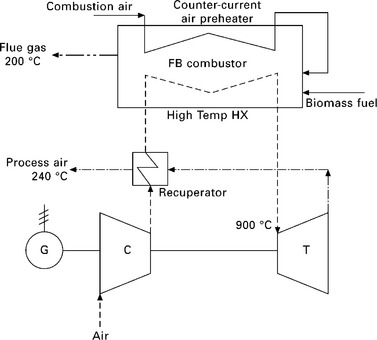
5.13 Process flow diagram of the biomass-fired hot air gas turbine with fluidised bed combustion (Gaderer et al. 2010).
5.4.3 Gasification-based biomass CHP technologies
Gasification-based biomass CHP technologies are probably the second most popular category of technologies for large- to micro-scale biomass CHP systems. For large-scale CHP systems, such as power plants, biomass gasification can be combined with gas turbines and/or steam turbines (integrated gasification combined cycle - IGCC) as adopted by some global manufacturers of power generation units/components such as General Electric (GE Power 2010). For small- and micro-scale biomass CHP systems, when gasification is adopted as the biomass conversion technology, there are three main choices for the prime mover: gas turbines, internal combustion engines and fuel cells. The success of the small- and micro-scale gasification-based CHP systems will depend largely on the quality of the combustible gases produced by biomass gasification - there are specific requirements for each prime mover in terms of gas quality and cleanliness (Liu and Neubauer 2010). Gas cleaning and conditioning of the combustible gases produced by biomass gasification can be very costly and energy intensive for small- and micro-scale gasification-based CHP units (Liu and Neubauer 2010).
Community Power Corporation (CPC), the Modular Bioenergy Company of the United States, has developed and commercialised biomass CHP systems which are based on the technologies of gasification and internal combustion engine with capacity ranging from 25 kWe to 75kWe (CPC 2010). Each of CPC’s CHP systems consists of a gas production module which contains a downdraft gasifier and gas cleaning equipment, etc., and a power generation engine which is either a spark ignition engine or a compression ignition engine. Schmitt Enertec GmbH of Germany (Schmitt Enertec 2010) commercially supplies biomass gasification and internal combustion engine-based CHP systems with capacity between 250 kWe and 1000 kWe. The specification of these CHP systems indicates that the electric power generation efficiency is ca. 26%, whereas the overall CHP efficiency is ca. 80% (Schmitt Enertec 2010). The combination of biomass gasification with a solid oxide fuel cell (SOFC) and/or micro gas turbine for small-scale CHP was assessed using Aspenplus™ process simulation software by Fryda et al. (2008). Karellas et al. (2008) investigated an innovative allothermal biomass gasification process - the Biomass Heatpipe Reformer (BioHPR), and its coupling with micro turbine and SOFC systems. M. Liu et al. (2010) carried out the feasibility study of applying biomass gasification to a SOFC system for distributed power/CHP generation in rural areas of China. Their preliminary system calculations indicated that an electrical efficiency of 32% and an overall CHP system efficiency of 59% were achievable with a 100 kWe biomass gasification-SOFC CHP system.
The development of biomass gasification-based micro-scale CHP systems is less advanced in comparison to the development of biomass combustion- based micro-scale CHP systems. This is partly due to developers’ and the general public’s perceptions and concerns about the safety issues of biomass gasification. The technical and economic challenges of biomass gasification may also have contributed to this phenomenon, considering that biomass combustion is a mature and well-developed biomass conversion technology.
5.4.4 Other biomass CHP technologies
There are various other technologies available for biomass combined heat and power generation, such as using bio-ethanol/bio-oil/biodiesel and biogas to fuel internal combustion engines and gas turbines/micro-turbines. As pointed out in Section 5.3, many internal combustion engines can burn a blend of gasoline and bio-ethanol, a blend of petroleum diesel and biodiesel, and biogas, and hence internal combustion engine-based CHP systems can be fuelled by liquid biofuels and biogas. A UK-based company, Ener-G Combined Power, commercially supplies biogas-fuelled CHP units within the size range of 30 kWe to 1950 kWe and biodiesel-fuelled CHP units with the size range of 130 kWe to 385 kWe (Ener-G 2010). Two 385 kWe biodiesel CHP systems are to be installed in the Museum of Liverpool and expected to be in operation in summer 2011 (CHPA 2010). Over the past decade, many turbine/micro-turbine manufacturers have developed gas turbines and microgas turbines which can successfully burn biogas such as the micro-turbines made by the Capstone Turbine Corporation of the United States (Capstone 2010). Capstone now commercially supplies biogas-fuelled micro-turbine power generating units within the size range of 30 kWe to 1000 kWe.
5.5 Conclusions
As a renewable energy resource, biomass has great potential to meet the world’s primary energy demand in the future. There are a range of technologies available which can convert bulky biomass feedstock into convenient forms of energy/fuels. Great advances have been made over the past decade with the development of small- and micro-scale biomass CHP systems with some of them having entered the commercial service stage. The demand for these CHP systems is set to continue to increase due to the combination of the mounting CO2 mitigation pressure, the expected price rises and the exhaustion of premium fossil fuels.
The development and implementation of micro-scale biomass-fuelled CHP systems, particularly for those with capacity in the order of a few kWe, which are ideal for building applications, are still hindered by technical and economic barriers. Significant research efforts are urgently needed and should be accelerated in order that the distributed micro-scale biomass-fuelled CHP systems can be demonstrated, commercialised and widely deployed in the near future.
5.6 Acknowledgements
The author wishes to acknowledge the financial support from the UK Technology Strategy Board (TPQ3082A), UK EPSRC (EP/E020062/1, EP/F038070/1 via ERA-NET Bioenergy) and the Carbon Trust (Project No. 089-051) for his groups’ research on biomass CHP, biomass gasification and biomass combustion at the University of Nottingham. The contributions of past and present research fellows (Dr L. Dong, Dr G. Qiu and Dr W. Zhang) and PhD students (Mr F. Daminabo, Ms Y. Shao, Mr J. Li and Mr I. Ul Hai) to the funded research projects are also acknowledged.
5.7 References
accessed 20 September 2010 Admont. Biomass fired CHP plant based on an ORC cycle - Project: ORC-STIA- Admont. http://ec.europa.eu/energy/res/sectors/doc/bioenergy/chp/bm_120_98.pdf, 2001.
Al-attab, K.A., Zainal, Z.A. Performance of high-temperature heat exchangers in biomass fuel powered externally fired gas turbine systems. Renewable Energy. 2010; 35:913–920.
Al-attab, K.A., Zainal, Z.A. Turbine startup methods for externally fired micro gas turbine (EFMGT) system using biomass fuels. Applied Energy. 2010; 87:1336–1341.
Alauddin, Z.A.B.Z., Lahijani, P., Mohammadi, M., Mohamed, A.R. Gasification of lignocellulosic biomass in fluidized beds for renewable energy development: a review. Renewable and Sustainable Energy Reviews. 2010; 14:2852–2862.
Alvira, P., Tomás-Pejó, E., Ballesteros, M., Negro, M.J. Pretreatment technologies for an efficient bioethanol production process based on enzymatic hydrolysis: a review. Bioresource Technology. 2010; 101:4851–4861.
Annalmalai, K., Puri, I.K. Combustion Science and Engineering. Boca Raton, FL: CRC Press; 2007.
Appels, L., Baeyens, J., Degrève, J., Dewil, R. Principles and potential of the anaerobic digestion of waste-activated sludge. Progress in Energy and Combustion Science. 2008; 34:755–781.
accessed 18 September 2010 Argent Energy Limited. http://www.argentenergy.com/, 2010
Atadashi, I.M., Aroua, M.K., Aziz, A.A. Biodiesel separation and purification: a review. Renewable Energy. 2010; 36:437–443.
Balat, M. Production of bioethanol from lignocellulosic materials via the biochemical pathway: a review. Energy Conversion and Management. 2011; 52:858–875.
Balat, M., Balat, M., Kirtay, E., Balat, H. Main routes for the thermo-conversion of biomass into fuels and chemicals - Part 1: Pyrolysis systems. Energy Conversion and Management. 2009; 50:3147–3157.
Basu, P.Biomass Gasification Design Handbook. New York: Academic Press, 2010.
accessed 4 October 2010 BEF. Biomass Energy Foundation website. http://www.woodgas.com/history.htm, 2010.
Biedermann, F., Carlsen, H., Obenberger, I., Schoch, M., Small-scale CHP plant based on a 75 kWel Hermetic eight cylinder Stirling engine for biomass fuels - development, technology and operational experiences2nd World Conference and Exhibition on Biomass for Energy. May, Rome, Italy: Industry and Climate Protection, 2004.
Binod, P., Sindhu, R., Singhania, R.R., Vikram, S., Devi, L., Nagalakshmi, S., Kurien, N., Sukumaran, R.K., Pandey, A. Bioethanol production from rice straw: an overview. Bioresource Technology. 2010; 101:4767–4774.
accessed 18 September 2010 Biodiesel. http://www.biofuels-platform.ch/en/infos/production.php?id=biodiesel, 2010
accessed 16 September 2010 Bioethanol. http://www.biofuels-platform.ch/en/infos/production.php?id=bioethanol, 2010
accessed 6 October 2010 BIOS. BIOS Bioenergiesysteme GmbH. http://www.bios-bioenergy.at/en/electricity-from-biomass/steam-turbine.html, 2010.
accessed 6 October 2010 BIOS. BIOS Bioenergiesysteme GmbH. http://www.bios-bioenergy.at/en/electricity-from-biomass/screw-type-engine.html, 2010.
accessed 12 October 2010 BIOS. BIOS Bioenergiesysteme GmbH. http://www.bios-bioenergy.at/en/electricity-from-biomass/orc-process.html, 2010.
accessed 8 October 2010 BIOS. BIOS Bioenergiesysteme GmbH. http://www.bios-bioenergy.at/en/electricity-from-biomass/stirling-engine.html, 2010.
Borjesson, P., Mattiasson, B. Biogas as a resource-efficient vehicle fuel. Trends in Biotechnology. 2007; 26:7–13.
Bridgwater, A.V., Meier, D., Radlein, D. An overview of fast pyrolysis of biomass. Organic Geochemistry. 1999; 30:1479–1493.
BS EN 14778-1Solid biofuels - Sampling - Part 1: Methods for sampling. London: British Standards Institution, 2005.
BS EN 14774-1Solid biofuels - Determination of moisture content - Oven dry method Part 1: Total moisture - Reference method. London: British Standards institution, 2009.
BS EN 14774-2Solid biofuels - Determination of moisture content - Oven dry method Part 2: Total moisture - Simplified method. London: British Standards institution, 2009.
BS EN 14774-3Solid biofuels - Determination of moisture content - Oven dry method Part 3: Moisture in general analysis sample. London: British Standards institution, 2009.
BS EN 14775Solid biofuels - Determination of ash content. London: British Standards institution, 2009.
BS EN 14918Solid biofuels - Determination of calorific value. London: British Standards institution, 2009.
BS EN 15148Solid biofuels - Determination of the content of volatile matter. London: British Standards institution, 2009.
accessed 23 September 2010 Capstone. Capstone Turbine Corporation. http://www.capstoneturbine.com/prodsol/solutions/rrbiogas.asp, 2010.
CEN/TS 15104Solid biofuels - Determination of total content of carbon, hydrogen and nitrogen - Instrumental methods. London: British Standards institution, 2005.
CEN/TS 15289Solid biofuels - Determination of total content of sulphur and chlorine. London: British Standards institution, 2006.
CEN/TS 15290Solid biofuels - Determination of major elements. London: British Standards institution, 2006.
CEN/TS 15297Solid biofuels - Determination of minor elements. London: British Standards institution, 2006.
CEN/TS 15296Solid biofuels - Calculation of analyses to different bases. London: British Standards institution, 2006.
Cherubini, F. GHG balances of bioenergy systems - overview of key steps in the production chain and methodological concerns. Renewable Energy. 2010; 35:1565–1573.
accessed 14 October 2010 CHPA. Combined Heat and Power Association (CHPA) press release. http://www.chpa.co.uk/media/760ae75d/21%2009%202010%20%20Huhne%20highlights%20key%20role%20of%20CHP%20-%20FINAL.pdf, 2010.
Cocco, D., Deiana, P., Cau, G. Performance evaluation of small size externally fired gas turbine (EFGT) power plants integrated with direct biomass dryers. Energy. 2006; 31:1459–1471.
accessed 21 September 2010 CPC. CPC website. http://www.gocpc.com/, 2010.
Demirbas, M.F. Potential applications of renewable energy sources, biomass combustion problems in boiler power systems and combustion related environmental issues. Progress in Energy and Combustion Science. 2005; 31:171–192.
Demirbas, M.F., Balat, M., Balat, H. Potential contribution of biomass to the sustainable energy development. Energy Conversion and Management. 2009; 50:1746–1760.
accessed 17 September 2010 DOE. US Department of Energy. Energy Efficiency and Renewable Energy. http://www1.eere.energy.gov/biomass/abcs_biofuels.html#prod, 2010.
Dong, L., Liu, H., Riffat, R.B. Development of small-scale and micro-scale biomass-fuelled CHP systems - a literature review. Applied Thermal Engineering. 2009; 29:2119–2126.
accessed 6 October 2010 EBB. European Biodiesel Board. http://www.ebb-eu.org/biodiesel.php, 2010.
accessed 16 September 2010 EIA IEO, International Energy Outlook 2010. Energy Information Administration, Official Energy Statistics from the US Government 2010. http://www.eia.doe.gov/oiaf/ieo/pdf/0484(2010).pdf
accessed 15 September 2010 EIA ISA-Biomass. US Energy Information Administration - Independent Statistics and Analysis. http://www.eia.doe.gov/oiaf/analysispaper/biomass.html, 2010.
accessed 14 October 2010 Ener-G. Ener-G Combined Power. http://www.energ.co.uk/index313.aspx#P3, 2010.
Enweremadu, C.C., Mbarawa, M.M. Technical aspects of production and analysis of biodiesel from used cooking oil - a review. Renewable and Sustainable Energy Reviews. 2009; 13:2205–2224.
accessed 8 October 2010 E.ON. Steven’s Croft Biomass Power Station. http://www.eon-uk.com/generation/stevenscroft.aspx, 2010.
Eriksson, O., Finnveden, G., Ekvall, T., Bjorklund, A. Life cycle assessment of fuels for district heating: a comparison of waste incineration, biomass- and natural gas combustion. Energy Policy. 2007; 35:1346–1362.
accessed 2 August 2010 European Biomass Industry Association. http://www.eubia.org/215.0.html, 2010
Fang, X., Shen, Y., Zhao, J., Bao, X., Qu, Y. Status and prospect of lignocellulosic bioethanol production in China. Bioresource Technology. 2010; 101:4814–4819.
Fischer, G., Schrattenholzer, L. Global bioenergy potentials through 2050. Biomass and Bioenergy. 2001; 20:151–159.
Fryda, F., Panopoulos, K.D., Kakaras, E. Integrated CHP with autothermal biomass gasification and SOFC-MGT. Energy Conversion and Management. 2008; 49:281–290.
Gaderer, M., Gallmetzer, G., Spliethoff, H. Biomass fired hot air gas turbine with fluidized bed combustion. Applied Thermal Engineering. 2010; 30:1594–1600.
accessed 2 August 2010 Gaur, S., Reed, T.B. An atlas of thermal data for biomass and other fuels, NREL. http://www.scribd.com/document_downloads/3120309?extension=pdf, 1995.
accessed 22 September 2010 GE Power. http://www.gepower.com/prod_serv/products/gasification/en/overview.htm, 2010
Gnansounou, E. Production and use of lignocellulosic bioethanol in Europe: current situation and perspectives. Bioresource Technology. 2010; 101:4842–4850.
Gnansounou, E., Dauriat, A. Techno-economic analysis of lignocellulosic ethanol: a review. Bioresource Technology. 2010; 101:4980–4991.
Goyal, H.B., Seal, D., Saxena, R.C. Bio-fuels from thermochemical conversion of renewable resources: a review. Renewable and Sustainable Energy Reviews. 2008; 12:504–517.
Hoefnagels, R., Smeets, E., Faaij, A. Greenhouse gas footprints of different biofuel production systems. Renewable and Sustainable Energy Reviews. 2010; 14:1661–1694.
Holm-Nielsen, J.B., Al Seadi, T., Oleskowicz-Popiel, P. The future of anaerobic digestion and biogas utilization. Bioresource Technology. 2009; 100:5478–5484.
Hoogwijk, M., Faaij, A., van den Broek, R., Berndes, G., Gielen, D., Turkenburg, W. Exploration of the ranges of the global potential of biomass for energy. Biomass and Bioenergy. 2003; 25:119–133.
accessed 3 August 2010 IEA Bioenergy. IEA Bioenergy Annual Report. http://www.ieabioenergy.com/DownLoad.aspx?DocId=6507, 2009.
IEA Bioenergy. Education website on biomass and bioenergy. http://www.aboutbioenergy.info/index.html, 2010. [accessed on 3 August 2010].
accessed 15 September 2010 IEA Bioenergy. Task 34: Pyrolysis. http://www.pyne.co.uk/index.php?_id=76, 2010.
accessed 1 August 2010 IEA WEO. IEA World Energy Outlook 2009. http://www.worldenergyoutlook.org/, 2009.
Jiang, J., Sui, J., Wu, S., Yang, Y., Wang, L. Prospects of anaerobic digestion technology in China. Tsinghua Science and Technology. 2007; 12:435–440.
Karellas, S., Karl, J., Kakaras, E. An innovative biomass gasification process and its coupling with microturbine and fuel cell systems. Energy. 2008; 33:284–291.
Kautz, M., Hansen, U. The externally fired gas turbine (EFGT-cycle) for decentralized use of biomass. Applied Energy. 2007; 84:795–805.
Khan, A.A., De Jong, W., Jansens, P.J., Spliethoff, H. Biomass combustion in fluidized bed boilers: potential problems and remedies. Fuel Processing Technology. 2009; 90:21–50.
Klass, D.L. Biomass for renewable energy and fuels, in Encyclopaedia of Energy, Volume 1. Elsevier Amsterdam. 193–212, 2004.
Knoef, H.A.M. Handbook Biomass Gasification. The Netherlands: BTG Biomass Technology Group BV; 2005.
Ladanai, S., Vinterback, J. Global Potential of Sustainable Biomass for Energy. Department of Energy and Technology, Swedish University of Agricultural Sciences Report 013; 2009.
Larkin, S., Ramage, J., Scurlock, J. Bioenergy. In: Boyle G., ed. Renewable Energy - Powerfor a Sustainable Future. Oxford: Oxford University Press; 2004:106–146.
Lemort, V., Quoilin, S., Cuevas, C., Lebrun, J. Testing and modeling a scroll expander integrated into an organic Rankine cycle. Applied Thermal Engineering. 2009; 29:3094–3102.
Liu, G., Zhao, Y., Li, L., Shu, P. Simulation and experiment research on wide ranging working process of scroll expander driven by compressed air. Applied Thermal Engineering. 2010; 30:2073–2079.
Liu, H., Neubauer, Y. Gasification. In: Lackner M., ed. High Temperature Processes in Chemical Engineering. Vienna: Verlag Process Eng Engineering GmbH; 2010:361–408.
Liu, H., Qiu, G., Shao, Y., Riffat, S.B. Experimental investigation on the flue gas emissions of a domestic biomass boiler under normal and idle combustion conditions. International Journal of Low Carbon Technologies. 2010; 5:88–95.
Liu, H., Qiu, G., Shao, Y., Daminabo, F., Riffat, S.B. Preliminary experimental investigations of a biomass-fired micro-scale CHP with organic Rankine cycle. International Journal of Low Carbon Technologies. 2010; 5:81–87.
Liu, M., Aravind, P.V., Woudstra, N., Cobas, V.R.M., Verkooijen, A.H.M. Solid oxide fuel cell integrated with biomass gasification for power generation for rural areas in China. http://ieeexplore.ieee.org/stamp/stamp.jsp?arnumber=05348036, 2010. [accessed 13 October 2010].
Ma, F., Hanna, M.A. Biodiesel production - a review. Bioresource Technology. 1999; 70:1–15.
Masters, G.M. Renewable and Efficient Electric Power Systems. New York: Wiley; 2004.
Mohan, D., Pittman, C.U., Jr., Steele, P.H. Pyrolysis of wood/biomass for bio-oil: a critical review. Energy & Fuels. 2006; 20:848–889.
Nigam, P.S., Singh, A. Production of liquid biofuels from renewable resources. Progress in Energy and Combustion Science. 2011; 37:52–68.
Obernberger, I., Thonhofer, P., Reisenhofer, E. Description and evaluation of the new 1000 kWel organic Rankine cycle process integrated in the biomass CHP plant in Lienz, Austria. Euroheat & Power. 2002. [10/2002].
Obernberger, I., Carlsen, H., Biedermann, F., State-of-art and future development regarding small-scale CHP systems with a special focus on ORC and Stirling engine technologies. International Nordic Bioenergy 2003 Conference. 2003. [Jyväskylä, Finland].
Peterson, R.B., Wang, H., Herron, T. Performance of a small-scale regenerative Rankine power cycle employing a scroll expander. Proc. IMechE Part A: J Power and Energy. 2008; 222:271–282.
Phyllis. ECN Phyllis - the composition of biomass and waste. http://www.ecn.nl/phyllis/, 2010. [accessed 4 October 2010].
Podesser, E. Electricity production in rural villages with a biomass stirling engine. Renewable Energy. 1999; 16:1049–1052.
Poeschl, M., Ward, S., Owende, P. Prospects for expanded utilization of biogas in Germany. Renewable and Sustainable Energy Reviews. 2010; 14:1782–1797.
Pritchard, D. Biomass combustion gas turbine CHP. ETSU B/U1/00679/00/REP. DTI Pub URN No. 02/1346. Talbott’s Heating Ltd. 2002.
Qiu, G., Liu, H., Riffat, S.B. Selection of expanders for micro-scale ORC-based CHP systems. Paper SE-066, SET2010, - 9th International Conference on Sustainable Energy Technologies. Shanghai, China, 2010. [24-27 August].
Quoilin, S., Lemort, V., Lebrun, J. Experimental study and modeling of an Organic Rankine Cycle using scroll expander. Applied Energy. 2010; 87:1260–1268.
Rao, P.V., Baral, S.S., Dey, R., Mutnuri, S. Biogas generation potential by anaerobic digestion for sustainable energy development in India. Renewable and Sustainable Energy Reviews. 2010; 14:2086–2094.
Reed, T., Gaur, S. A Survey of Biomass Gasification 2001, 2nd edn. Franktown, CO: The Biomass Energy Foundation; 2001.
RWE. Markinch Biomass CHP. http://www.rwe.com/web/cms/en/429432/rwe-npower-renewables/sites/projects-in-construction/biomass/markinch-biomass-chp/project-details/, 2010. [accessed 8 October 2010].
Schmitt Enertec. http://www.schmitt-enertec.com/wood_gasification/woodgas_power.htm, 2010 [accessed 21 September 2010].
Schuster, A., Karellas, S., Kakaras, E., Spliethoff, H. Energetic and economic investigation of Organic Rankine Cycle applications. Applied Thermal Engineering. 2009; 29:1809–1817.
Singh, S.P., Singh, D. Biodiesel production through the use of different sources and characterization of oils and their esters as the substitute of diesel: a review. Renewable and Sustainable Energy Reviews. 2010; 14:200–216.
Sunmachine. http://www.sunmachine.de/produkte.php, 2010 [accessed 21 September 2010].
Sunpower. http://www.sunpower.com/index.php?pg=25, 2010 [accessed 21 September 2010].
Talbotts. Talbotts Generators Limited. http://www.biomassgenerators.com/docs/BG25%20Brochure.pdf, 2010. [accessed 12 October 2010].
Talebnia, F., Karakashev, D., Angelidaki, I. Production of bioethanol from wheat straw: an overview on pretreatment, hydrolysis and fermentation. Bioresource Technology. 2010; 101:4744–4753.
Thiers, S., Aoun, B., Peuportier, B. Experimental characterization, modeling and simulation of a wood pellet micro-combined heat and power unit used as a heat source for a residential building. Energy and Buildings. 2010; 42:896–903.
Turboden. http://www.turboden.eu/en/products/products-chp.php, 2010 [accessed 20 September 2010].
Van Loo, S., Koppejan, J. The Handbook of Biomass Combustion and Cofiring. London: Earthscan; 2007.
Wang, H., Peterson, R.B., Herron, T. Experimental performance of a compliant scroll expander for an organic Rankine cycle. Proc. IMechE Part A: J. Power and Energy. 2009; 223:863–872.
Wang, L., Weller, C.L., Jones, D.D., Hann, M.A. Contemporary issues in thermal gasification of biomass and its application to electricity and fuel production. Biomass and Bioenergy. 2008; 32:573–581.
Ward, A.J., Hobbs, P.J., Holliman, P.J., Jones, D.L. Optimisation of the anaerobic digestion of agricultural resources. Bioresource Technology. 2008; 99:7928–7940.
WhatGreenCar. http://www.whatgreencar.com/bioethanol.php, 2010 [accessed 6 October 2010].
Wu, C., Yin, X., Ma, X., Zhou, Z., Chen, H. Design and operation of a 5.5 MWe biomass integrated gasification combined cycle demonstration plant. Energy & Fuels. 2008; 22:4259–4264.
*EU Cogeneration Directive 2004/8/EC defines ‘small-scale’ CHP units as those with electrical power output capacities less than 1000 kWe, whereas ‘Micro-scale’ CHP units are those with electrical power output capacities less than 50 kWe.