
Small combined heat and power (CHP) systems for commercial buildings and institutions
Abstract:
Small-scale CHP has a huge potential to deliver energy savings and be an effective carbon mitigation strategy in commercial buildings and institutions. This chapter starts with a brief discussion about energy requirements, trends, and the regulatory frameworks driving energy efficiency in these types of buildings. Then details on technical and operational characteristics of small-scale CHP technology are given with emphasis on implementation in different types of buildings. Finally, future prospects and ways to support the technology are discussed.
15.1 Introduction
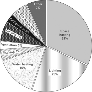
The UK’s long-term manifesto on reducing carbon emissions is supported by the Climate Change Act 2008 that sets out a target of cutting greenhouse gas emission by at least 34% and 80% by the years 2020 and 2050, respectively, against the 1990 baseline (UK Parliament, 2008). This means significant emission cuts will have to be realised in each of the three main sectors of the economy responsible for the bulk of greenhouse gas emissions: the power generation sector, the transport sector, and the building sector. The latter consumes about 45% of the total primary energy and contributes to a corresponding amount of pollutants emission. The UK has a stock of about 1.8 million non-domestic buildings, which account for up to 18% of total CO2 emissions. These buildings consume approximately 300 TWh of energy a year, predominantly for the provision of space heating and cooling, hot water, and power for lighting and office equipment, as shown in Fig. 15.1 (Elsadig, 2005).
Energy consumption of the existing building stock can vary widely as it is influenced by the design of the building envelope and the efficiency of the heating, ventilation and air conditioning (HVAC) equipment (Baird et al., 1984). The UK Building Regulation Part L2, conservation of fuel and power in non-domestic buildings, and the Eu’s Energy Performance of Buildings Directive (EPBD), are the main tools for change towards sustainability in the building sector. The EPBD requires display energy certificates (DECs) in public and commercial buildings and energy performance certificates (EPCs) to be made available at point of sale or rent. The EPCs rating of a building carries, among other benefits, help to identify poorly operated buildings and a list of remedies that can be taken to improve the overall energy performance of the building (EU Parliament, 2002). The UK building regulations are continually evolving for tighter building construction and operation standards. For instance, Part L of the proposed 2011 building regulations will include 20% improvements in building energy performance. Eventually, it is intended to have building regulations enforcing a target of zero carbon emissions for domestic and non-domestic buildings in 2016 and 2019, respectively.
15.2 Basic issues and energy requirements
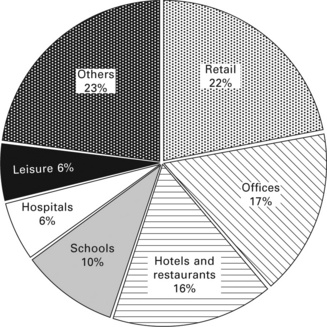
In the UK, information regarding energy consumption in non-domestic buildings is generally not easily available and not explicitly compiled compared to the industrial and domestic sectors. This is due in part to the diverse nature of buildings with different physical forms and sizes that fall in this category and which are used in a wide range of activities including industrial, commercial, public service, transport and agricultural sector. Figure 15.2 shows a sample of non-domestic buildings with different economic activities and the proportional energy consumption (Pérez-Lombard et al., 2008). Furthermore, these types of buildings would often be serviced by plant and equipment with varied power capacities, presenting a major difficulty for collecting accurate and reliable statistical data and producing standardised energy consumption patterns. The implementation of the DECs scheme may offer an opportunity to improve the national database and establish an accurate benchmark of energy consumption in this sector of the economy.
Recent energy consumption statistics in the UK non-domestic building stock normalised by floor area (i.e., kWh/m2) show an increase of about 5% between 1990 and 2008. This upward trend is mainly a reflection in increased electrical energy consumption that follows from the overall increase in the commercial sector floor space. The improvement in efficiency of building services equipment slowed down the increase in energy use for air conditioning, refrigeration, lighting, IT, and long opening hours in large retail stores.
It is increasingly recognised that investment in the energy efficiency of buildings has, in addition to cutting the cost of energy used and supporting efforts for climate change mitigation, the benefit of improving occupants’ productivity and health (Scrase, 2000). The deployment of commercially available renewable energy and low carbon technologies to provide space heating, air conditioning and lighting could contribute to substantial carbon savings in non-domestic buildings. However, the high cost of deployment of renewable energy technologies (PV, heat pumps, etc.) makes returns on investment unattractive to potential investors. Combined heat and power (CHP) is, however, a proven and reliable technology that can reduce carbon emission and be cost effective.
15.3 Small combined heat and power (CHP) use in commercial buildings and institutions
The adoption of CHP systems as an energy supply option in industry and district heating schemes is well established in the UK and the developed countries. CHP systems can be found in all sectors of the UK economy, from individual dwellings to heavy industries and processes and large district heating schemes. In 2008, the UK total CHP electricity generation capacity stood at around 5.5 GWe with a heat-to-power ratio of 1.87 and an overall thermal efficiency of 67.2% (DUKES, 2008). Most of the power is generated from large-scale CHP plants installed in the industrial sector (oil, gas, chemicals and paper industries). Electrical power generated from CHP plants installed in the building sector, however, accounts for only around 344 MWe, representing just over 7 per cent of the UK’s total CHP capacity (DUKES, 2008). Because of the small-scale nature of the CHP plants installed in buildings, these constitute over 90% of the total number of CHP installations. To reduce carbon emissions and help deliver the Climate Change Programme, the UK has a target of achieving at least 10 GW of Good Quality CHP electrical power capacity by the end of 2010. however, this seems unlikely to be met on current trends as growth in installed CHP capacity has stagnated in the last few years.
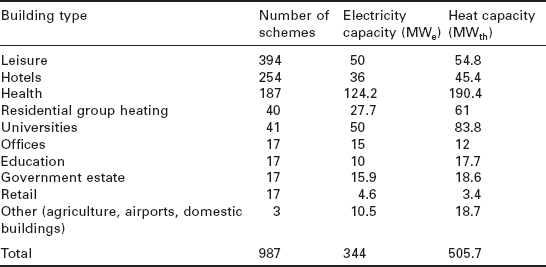
The use of small-scale CHP plants to provide heat and power in the building sector was first introduced in buildings where there is year round demand for both heat and power such as sport centres, hospitals and hotels. Current applications for small CHP in buildings has been extended to encompass universities, schools, tower buildings, sheltered housing schemes, military bases and even farms. Most small-scale CHP plant are built as complete units on a common frame with enclosure with electrical power rating ranging from as low as 30 kW to up to 2 MW. Table 15.1 gives a summary of the total number of small-scale CHP schemes and power generation capacity in different types of commercial buildings and institutions (DUKES, 2008). It can be seen that the largest proportion of the CHP capacity is installed mainly in hospitals, whereas leisure centres and hotels have the largest number of installations.
Generally, the basic common requirement for a small-scale CHP is to satisfy the electricity and heat demand in a building with operation in excess of 4500 hours per year or about 14-16 hours/day to be economic (CIBSE,2007). The traditional intermittency operation of a boiler, to provide heat in a building only when required, is not compatible with the mode of operation of a CHP system. A small-scale CHP should operate continuously and be sized to have a heat-to-power ratio comparable to that of the building it intends to service. A departure from full-load operating conditions impacts negatively on the thermal efficiency of a CHP system and hence results in longer payback period. Correspondingly, the outlet temperature level should be suitable for the heating application. For instance, the minimum required temperatures in building applications vary from 40 °C, where underfloor heating is used, to 80 °C for conventional radiators. Thus, a temperature of approximately 100 °C can be regarded as the sufficient output temperature of a CHP system. Therefore, while the overriding aim of installing and sizing a CHP system will be to supply all normal electricity and heat load, in practice this is not always realistic and supplementary grid power and heat from a standby boiler will be considered as part of an overall design strategy.
15.4 Small-scale combined heat and power (CHP) technology
CHP technologies are traditional power generation equipment where the attendant heat from fuel energy conversion into mechanical or electrical energy is recovered for heating or cooling purposes. In this way, small- scale CHP systems can convert up to 80% of the energy in the fuel (GCV) into electrical power and useful heat. This compares favourably with the conventional method of supplying heat and power to buildings from a heat- only boiler and grid.
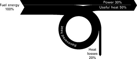
Most small-scale CHP units used in buildings come as packaged plant built around an engine with all components assembled and ready for connection to a building’s heating and hot water circuit and electrical distribution panels. Approximately 30% of engine fuel energy input is converted to mechanical power to drive the electric generator, where the conversion into electricity occurs with little loss. Of the remaining energy released in the engine, over 50% can be recovered as useful heat using a heat recovery system. The heat recovered for small-scale CHP is in the form of low temperature hot water (LTHW) at between 70 and 90 °C. A further 10% of available heat can also be recovered at low temperatures of 30 to 50 °C. Figure 15.3 shows a Sankey diagram of energy balance for a small-scale packaged CHP system.
Other associated equipment with a small-scale CHP system include a control and monitoring panel that operate the engine start-up and shut-down sequences to ensure safe functioning, an exhaust system with compatible materials, and an acoustic enclosure to attenuate noise emanating from the plant.
15.4.1 Heat engine types
The heat engine, also known as the prime mover and the term ‘engine’ will be used throughout this chapter, is the main component of a CHP system. The heat engine, which is referred to here as simply engine, is used to drive an electric generator to convert fuel energy into electricity. Commonly, there are three types of engines used in small-scale CHP for buildings.
Reciprocating internal combustion
There are two well-known types of reciprocating engine used in small-scale stationary power generation and CHP applications: the spark ignition (Otto cycle) engine and the compression ignition (Diesel cycle) engine. The main difference between the two types is the method of igniting the fuel. Spark ignition engines use a spark plug to ignite a pre-mixed air/fuel mixture introduced into the cylinder. In Diesel engines, the fuel is injected into the cylinder at high pressure after the introduced air has been compressed to a high pressure, raising its temperature to the auto-ignition temperature of the fuel. The thermal efficiency of internal combustion engines depends primarily on the compression ratio of the fuel-air mixture in the cylinder with a typical range of 12-24 for diesel engines and 9-12 for spark ignition engines. This makes diesel engines achieve thermal efficiencies of up to 45% whereas that of its spark ignition counterpart is limited to about 35%.
The spark ignition engines are based on automotive or marine (industrial) engine derivatives converted to run on gaseous fuel such as natural gas. These engines are available in sizes from down to 20 kW and up to 5 MW electrical power output. The automotive derived engines are usually rated below 200 kW electrical power output rating whereas the industrial counterparts have a higher power output rating.
In addition to CHP applications, diesel engines are widely used to provide standby power in sites such as hospitals and data servers that require uninterruptible power supply to protect critical services. Converted diesel engine standby generators for small-scale CHP are often limited to sites where the electrical power demand is in excess of 500 kW and run on diesel fuel or diesel/gas dual fuel.
The reciprocating engines have proven reliability, low maintenance requirements and good service life. Depending on the engine size, a full engine overhaul is only required after achieving between 20 000 and 50 000 running hours.
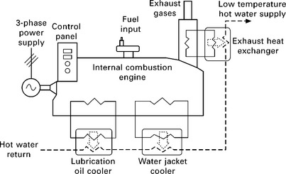
The economic benefit of a small-scale CHP is enhanced by effective recovery and use of the thermal energy rejected from the engine. Approximately 60-70% of the inlet fuel energy appears as heat energy, a proportion of which can be recovered from the engine exhaust gas, jacket cooling water, lubrication oil and turbocharger cooling water, and electric generator coolant. The exhaust gas leaves the engine at a typical temperature range of 450-650 °C, contains about 10-30% of the fuel energy while heat in the engine jacket coolant accounts for about 30% of fuel energy input. The heat recovered from the engine is generally in the form of low temperature hot water (90 °C) or low steam at a pressure lower than 2 barg. Figure 15.4 shows the main components and heat flow paths in a gas-fired internal combustion engine.
Reciprocating engines for small-scale CHP are a well developed and proven technology. They offer low initial cost, easy to start up, good reliability and availability with a proper maintenance schedule. Better control of the combustion process and use of exhaust catalysts have led to a significant improvement in greenhouse gas (GHG) emissions. However, because a large proportion of the heat energy rejected is of low grade, the ability of the engine to produce steam is limited. However, this is less critical in commercial and institutional buildings.
Gas turbines
Gas turbines are an established technology that is widely used by utility and industrial power generators. These are often modified aero-engines where part of fuel (e.g., natural gas or gas-oil) energy released in the combustion chamber is converted to electrical power at an efficiency ranging from 20 to 35%. Combustion gases exiting the turbine at a temperature over 450 °C are a source of high grade thermal energy. The rejected heat from the exhaust gases can be recovered as steam or hot water in an unfired or fired heat recovery boiler. Depending on size and operating properties of the gas turbine, the recoverable heat-to-power generation ratio can vary between 1.5 and 3. The heat-to-power ratio can be increased to over 6 by further fuel combustion in the waste heat recovery boiler to take advantage of excess oxygen content of the exhaust gases from the gas turbine. Hence this is very useful for sites with variable heat loads.
The available high quality waste heat, high reliability, and low maintenance costs per unit of power generation make gas turbines the favourite candidates for industrial and commercial CHP applications. Gas turbines can be used in small-scale CHP systems with power output ranging from just under 1 MW to a few MWs. However, the number of sites suitable for gas turbine-powered CHP systems in commercial buildings and institutions is usually limited to those with high pressure steam demand and electricity loads above 1 MW. In practice, gas turbines form a very small percentage of all CHP systems installed in buildings and are mainly confined to large hospitals where a small proportion of heat demand is in the form of steam used for medical equipment sterilisation.
Micro-gas turbines
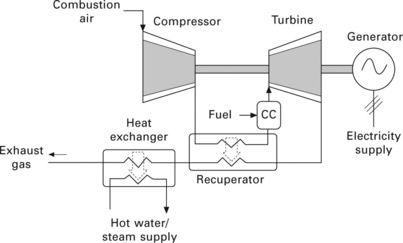
Micro-gas turbines are small combustion gas turbines with power output ranging from 30 kW to over 200 kW. The scaling down of gas turbine technology impacts negatively the heat and combustion processes which reduces the turbine power output and efficiency. Hence micro-gas turbines often operate at very high shaft speed (up to 100 000 rpm) and use electronic power inverters for power conditioning to generate a.c. voltage and at grid frequency. Equally, a heat recuperator is usually fitted in the exhaust hot gases to pre-heat compressed combustion air to reduce fuel consumption and achieve efficiencies of up 30%. Micro-gas turbines also offer the advantages of compact size, low weight per unit power, multi-fuel capability and ease of emissions control. Figure 15.5 shows a schematic diagram of a microgas turbine.
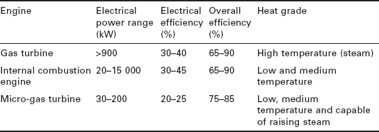
The introduction recently of packaged micro-gas turbines has offered comparable capital costs to reciprocating internal combustion engines with the benefit of lower maintenance costs and high availability, offsetting the lower electrical efficiency. The main application for micro-gas turbines is in packaged small-scale CHP which can be installed as single or multiple units, achieving an overall efficiency higher than 80%. Micro-gas turbines can also be used for emergency or standby power generation as well as a mechanical drive for pumps and compressors. Typical performance characteristics of the main engines used in small-scale CHP plants are summarised in Table 15.2.
15.4.2 Integration of small-scale CHP into building services
Heating and hot water services
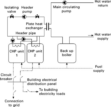
Heat supply in buildings is mostly required for space heating and hot water, and heat is recovered from small-scale CHP systems at about 80 °C when reciprocating internal combustion engines are used. Where steam is required, this can be generated directly from the exhaust gas heat recovery heat exchange of the engine or a micro-gas turbine. A working fluid (e.g., water) is circulated in a closed loop pipe work that includes backup boilers to transfer heat to the site heat loads. A plate heat exchanger, located on the return feed of the heating system of the building, offers a practical method of interface between the CHP header pipe and the heating circuit, as shown in Fig. 15.6. This series connection arrangement in particular offers an easy method of incorporating packaged CHP units into existing boiler-only heating systems in buildings. In new CHP installations where the CHP system is sized to provide a substantial amount of heat demand, then the CHP unit can be installed in parallel with the backup boilers. Regardless of the adopted installation arrangement, the CHP unit should operate as lead boiler to maximise the number of running hours and the boilers provide a spare heating capacity to be used at times of peak load.
Packaged CHP units using internal combustion engines are usually designed to operate within a range of water supply and return temperatures (e.g., 80/70 °C ± 3 °C) and any deviation from this range will cause the engine controls to shut down the unit. Hence the building heating system must be correctly sized in terms of heat dissipation, water flow rates, water supply and return temperature to eliminate frequent start and stop cycles.
Electric services
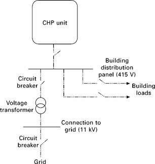
The selection of a small-scale CHP unit for buildings is usually based on supplying the building with as much heat and electrical power as economically viable to satisfy onsite energy loads. In most cases small-scale CHP systems in buildings will be operated in parallel with the public electricity supply network to export or import power as the electricity load profile of the site dictates. Connecting the CHP unit to a distribution network introduces a new source of energy which may increase the ‘fault level’ in the distribution network (i.e., the fault current that may flow when a fault occurs) and render its detection and isolation difficult. The power generated by a small-scale packaged CHP would commonly be three-phase voltage at 415 V or 11 kV and frequency of 50 Hz. Alternatively, a step-up transformer could be used to increase a generator voltage from 415 V and 11 kV to supply electricity to site. Figure 15.7 shows a simplified single line diagram of a CHP electrical connection.
Prior to connecting a CHP plant to a low voltage grid, it is the building operator’s responsibility to inform the distribution network operator (DNO) and approval must be obtained before the connection can take place. The power generation at low voltage in a small-scale CHP in commercial and institution buildings means that connection to the grid will be mostly covered under Electricity Association Engineering Recommendation G59/1. The engineering recommendations set out the conditions for the generator to maintain fault duration, voltage and frequency variations within statutory limits. When run in parallel mode, the CHP must be equipped with adequate protection equipment so that the plant is automatically disconnected in the event of an electrical failure or fault.
In building sites where backup power is required to maintain critical service operation during an outage of local area power distribution systems, small- scale packaged CHP can operate in island mode by shedding non-critical loads. However, for an islanding mode of operation, the electric generator must be of synchronous type and the CHP plant must also be fitted with grid synchronisation equipment which would increase the cost of the system.
Management of exhaust gases
Small-scale CHP plant rooms are often located in the basement or rooftop of buildings with strong mounting platform. In common with boilers, adequate volumetric flow rates of ambient air is drawn in from an outdoor intake to the plant room for combustion and ventilation of the plant room. The exhaust system is then used to discharge the combustion products away and at an outlet point from which it cannot be re-circulated into the building ventilation system. hence often exhaust duct outlets are extended to building roof level with due consideration for compatible duct material, insulation and vibration isolation.
15.5 Application of small-scale combined heat and power (CHP) technology in buildings
Commercial and institution buildings are complex structures with challenging operational requirements. Energy performance of a building depends on adequate use of passive energy strategies such as improved building envelope, maximising use of day time lighting, passive cooling and ventilation as well as its interface with the heating and power services. The UK and EU have made strong commitments to reducing GHG emissions from buildings through tougher building construction standards and integration of renewables and energy efficient systems (UK Parliament, 2008). This carrot-and-stick approach rewards building operators by earning higher display energy certificate (DEC) rating, avoiding climate change levy on consumed fuel and generated power, and attracting renewables obligation certificates (ROCs) when biomass fuel is used. hence, small-scale CHP is currently the technology of choice for the provision of heat and power in new and refurbished commercial buildings and institutions, as it is a more cost effective technology than renewables.
15.5.1 CHP systems in large office buildings
The increase in energy consumption in UK commercial buildings is partly due to rapid growth in floor space with offices, for instance, occupying almost twice as much floor space as in 1970 (Scrase, 2000). Despite improvement in energy efficiency of engineering services, this has led to a rapid growth in energy consumption particularly for space air conditioning, IT equipment and light.
The good practice energy consumption in offices in the UK ranges from 112 kWh/m2 per year for naturally ventilated buildings, to 348 kWh/m2 per year for prestigious air conditioned buildings (BRE, 1998). The energy consumed in prestigious office buildings is heavily skewed towards the use of electricity to run traditional vapour compression chillers for space air condition. Hence the proportion of energy used as heat compared to electricity varies widely in commercial office buildings. On average the heat-to-electricity demand ratio ranges from 0.54 for prestigious office buildings to 2.4 for naturally ventilated buildings.
Hence CHP systems become attractive in office buildings with high heat- to-power ratio as demand for space heating is important. Existing packaged CHP using internal combustion gas engines have a heat-to-power ratio in the range of 1 to 2 which can service this type of building adequately. Equally, in prestigious office buildings where substantial demand for electricity for space air conditioning, thermally activated absorption chillers using waste heat from the CHP system can practically replace traditional vapour compression chillers to reduce overall energy consumption. It is estimated that deployment of small-scale CHP in commercial office buildings could reduce overall C02 emissions in this sector by 5-22% (BRE, 1996).
15.5.2 CHP systems in higher education institutions
The higher education sector has been at the forefront of innovation in building sustainability as capital allocations by the higher education funding authorities are increasingly tied to the achievement of sustainability targets. The UK university estate is large and diverse which has a built floor area approaching 25.4 million m2 of floor space (Building, 2009). In 2006, the total energy consumption of the higher education institutions (HEI) was about 8.2 GWh which represents roughly 3.5% of the total energy consumption for the UK service sector. The average energy consumption intensity across all the institutions stands approximately at 287 kWh/m2. This average value is, however, above the 162 kWh/m2 recommended in the best practice benchmark of Higher Education Environmental Performance Improvement (HEEPI) (Ward et al., 2008). Energy rating of all new and refurbished buildings in this sector is expected to achieve a BRE Environmental Assessment Method (BREEAM) rating of ‘good’ or ‘excellent’, whereas the long-term target is to work towards zero net carbon emissions which is planned to be introduced in 2019.
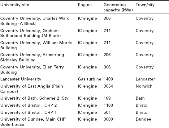
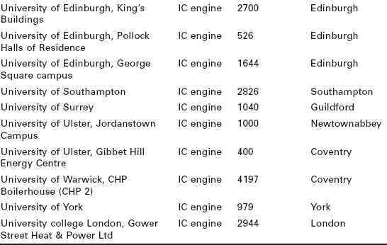
Electricity and gas are the main forms of energy used in HEI buildings, accounting for 37.6% and 53.5%, respectively. Assuming that gas is used mainly for space heating and hot water, then the ratio of heat to power demand is about 1.4. Therefore, HEI buildings present a favourable electrical-to-total thermal ratio for integration of small CHP systems. Small CHP use in the education sector has had a successful track record in many institutions. Table 15.3 shows a sample of current small-scale CHP schemes in university campuses in the UK (DUKES, 2008). It is shown that gas-fired reciprocating engines are overwhelmingly the technology of choice for this type of building.
The following describes two typical gas-fired small-scale CHP schemes used in higher education institutions.
Small-scale CHP at the University of Edinburgh
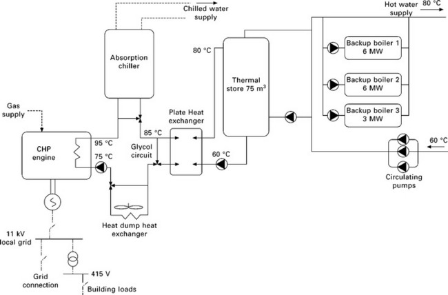
Since 2003, the University of Edinburgh has installed three small-scale CHP systems on its campuses. One of the CHP systems was installed in 2005 on George Square campus to provide heat, power and cooling. The £7 m CHP system investment comprises one 1.6 MW power output gas-fired GE Jenbacher 612 internal combustion engine; two 6 MW and one 3 MW low-temperature hot water backup boilers; a 600 kW absorption chiller exploiting byproduct heat to cool specialist laboratories in summer; and a 75 m3 thermal store (Somervell, 2006). The CHP engine thermal output is 1.7 MW, a fuel to electrical energy conversion efficiency of 42% and an overall efficiency of 86%. Although the CHP runs in parallel with the grid, the building energy controls have been set up so that the CHP operates on no-exporting mode by supplying all site power loads while retaining a small inflow from the grid. The current feed-in tariff makes exporting surplus electricity to grid unattractive.
In its first full year, the combined CHP and cooling system saved £220 000 in energy costs and 1250 tonnes of C02 emissions. It is projected that by further optimisation of electricity generation, annual savings of nearer £500 000 could be realised. A simplified schematic layout of the CHP system is shown in Figure 15.8.
Small-scale CHP at the University of Dundee
Steady growth in electricity consumption at Dundee University has led to identifying that small-scale CHP represented the most realistic mechanism for controlling electrical energy costs and an initial feasibility study was undertaken in 1988. However, it was not until 1995 when an improvement in heat-to-power ratio demand profile, coupled with lower gas prices and rising electricity costs, allowed the CHP project to be launched. The small-scale CHP plant consists of three Jenbacher J320G5-BO5, 4 stroke 20 cylinder spark ignition gas-fired engines rated at 1002 kW power output each. Each engine drives a 3.3 kV alternator at 1500 rpm (DUUSCo, 2009). Heat recovery from exhaust gas, first stage turbo intercooler and jacket water is passed by plate heat exchangers into the returning of existing district heating system water before it enters the boiler plant. When water conditions permit, all the available heat is utilised in the pre-heating function, otherwise some of the jacket heat is used to heat nearby buildings, and any surplus is dissipated to atmosphere by heat damping coolers. Electrical power from the CHP plant is then fed into the university’s 11 kV distribution network via a 4 MVA voltage step up transformer. The CHP plant is fully computerised and is set to operate in load-following mode with output level set to minimise the electricity importation rate. Each engine generator unit is fitted with a comprehensive monitoring system which is connected via modem link with the system suppliers who are contracted for a long-term maintenance agreement.
As the boiler plant forms part of an academic teaching building, noise and vibration generated by the engines become an important issue to be resolved. Hence an acoustic enclosure and vibration isolation equipment were fitted to prevent transmission through the building structure. The noise level emanating from air fans of the outside heat damping units also needed to be kept below 37 dB(A) as these were in proximity to adjacent residential property. Hence the cooling units were fitted with multiple slow running fans each having two silencers, and electronic speed control ensures that the fans start and speed up progressively to avoid any sudden changes in the perceived sound level.
15.5.3 CHP systems in health care buildings
Health care buildings are the most energy intensive buildings in the commercial and institution sector as they are usually occupied 24 hours per day, all year round and they require a careful control of the internal climate. In the UK, existing health care buildings are often old and operating outside the energy performance indicator of 55-65 GJ/1003 of heated volume. In 2008, energy consumption in National Health Service (NHS) England buildings amounted to about 9465 GWh, of which 45% was electricity and causing around four million tonnes of CO2 to be discharged to the atmosphere (NHS, 2009a,b).
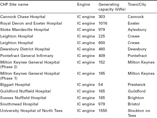
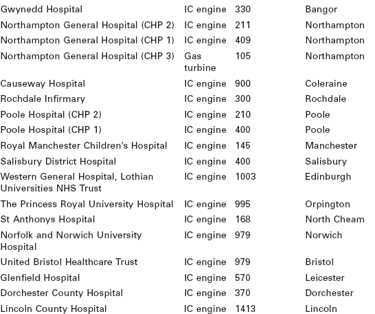
The health care buildings’ typical energy demand for thermal energy for space heating, hot water and electrical power is often required simultaneously most of the time with an average load factor above 80%. Therefore, hospitals buildings represent an ideal case for the application of CHP technologies. Table 15.4 shows a sample of existing small-scale CHP scheme installations of less than 2 MW power output in hospitals across the UK (DUKES, 2008). All the listed CHP installations are gas-fired internal combustion engines.

An example of a typical gas-fired small-scale CHP scheme has been installed in Royal Shrewsbury hospital. In 2004, an energy audit of the hospital commissioned by Shrewsbury and Telford NHS Trust showed the primary energy consumption stood at around 100 GJ /100 m3, nearly double the NHS target indicator. The study identified small-scale CHP as the best way of improving the hospital’s energy efficiency (EnerG, 2007).
In 2007, a small-scale CHP system using a gas-fired Caterpillar internal combustion engine with a rated power output of 1150 kW was installed. The CHP system provides nearly 1.7 MW of thermal energy in the form of both medium temperature hot water and steam at 120 °C. This is supplemented by a dual-fired backup boiler. The unit is also connected to a 700 kW absorption chiller, installed as part of the CHP scheme. The scheme was delivered through a fully funded performance contract with annual savings of £780 k guaranteed for 15 years (EnerG, 2007).
Similarly, a small-scale CHP has been installed in a purpose-built energy centre at Birmingham Heartlands, a major general hospital managed by Heart of England NHS Foundation Trust, to provide heat, power and cooling. The CHP project cost was £5 million and financed by EnerG Combined Power Ltd through Public Private Partnership agreement with a £403 000 grant from the Carbon Trust under the Community Energy Programme. The project is estimated to save £688 000 a year and cut emissions of CO2 by 1627 tonnes per year (EnerG, 2007). The CHP systems has a 1165 kW power output capacity MTU gas-fired engine with a heat output of 1272 kW and is also equipped with steam raising capability, backup boilers and a 300 kW absorption cooling system which operates off the gas engine waste heat and serving to meet the air conditioning demand during warmer months of the year.
15.5.4 CHP systems in leisure and recreation buildings
Leisure, recreation and accommodation buildings have a steady demand for heat for space heating, catering and showering for up to 24 hours a day, making CHP very cost effective. Where swimming pool facilities are installed, the heat and electricity demand increase substantially specifically for heating water and ventilating the pool hall, and the case for CHP becomes even more compelling (Carbon Trust, 2008). Actual energy consumption in leisure and recreation buildings with pool facilities could be as high as 237 kWh/m2 and 1336 kWh/m2 per year for heat and electricity, respectively, compared to good practice of 152 kWh/m2 and 573 kWh/m2, respectively (ETSU, 2001).
The leisure and recreation industry has been an excellent example for application of CHP to lower energy costs. Current small-scale CHP systems in the UK’s leisure and recreation buildings contribute more than 20 MW to the total of UK electricity generation capacity. With a few exceptions, most of the plants use gas-fired internal combustion engines with power output ranging from as low as 40 kW to over 500 kW (DUKES, 2008). For instance, David Lloyd Leisure has more than 46 small-scale CHP plants with another dozen units planned for the next few years in new buildings or as retrofit to existing building services. It is projected that electrical and heat output of 73 GWh and 115 GWh a year, respectively, will be supplied with energy bill savings of £0.9 million and reduction in carbon emissions of 16 000 tonnes a year (EnerG, 2008).
15.5.5 CHP systems in supermarkets and hypermarkets
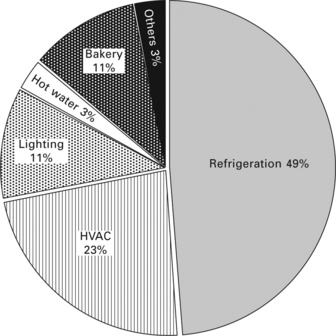
A typical supermarket in the UK uses about 1200 kWh of electricity and 260 kWh of gas per square meter of floor sales area per year compared to the industry benchmark of 915 kWh/m2 for electricity and 200 kWh/m2 for fossil fuels (CIBSE, 2004). Figure 15.9 presents a breakdown of a typical UK supermarket energy consumption. It is shown that approximately 75% of the energy is used for powering vapour compression refrigerators/freezers and HVAC equipment, whereas energy consumption for hot water is very modest. Hence, implementation of CHP in the classical way would result in underutilisation and limited primary energy savings. To increase the utilisation time, excess heat generated by the CHP plant would be used to drive an absorption chiller to displace grid-electricity operated food cooling equipments. The application of an integrated CHP/absorption scheme (trigeneration) in the supermarket can increase the attractiveness of small-scale CHP by utilising available waste heat to shift cooling from an electricity load to a thermal load in a very cost effective way (Zogg and Brodrick, 2005).
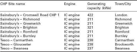
The use of integrated small-scale CHP with heat driven absorption chiller is also an environmentally benign way that would provide heat, power and cooling/refrigeration at a substantial reduction in CO2 emissions. This could be realised in addition to reducing overall energy consumption, by using alternative refrigerants to hydrofluorcarbons (HFCs) with zero or low global warming potential, such as water and ammonia, with further benefit of gaining additional BREEAM points. Table 15.5 shows an example of current small-scale CHP installation in supermarkets in the UK (DUKES, 2008).
15.6 Performance analysis and optimisation
Energy consumption patterns in commercial and institution buildings are complex and depend on type, size and activity carried out in the building. Hence a successful implementation of a small-scale CHP scheme requires conducting a detailed feasibility study of the building’s energy consumption patterns. This usually identifies accurately the building’s demand for all heat energy grades, electrical power and cooling. Then a daily and seasonal load profile for each form of energy demand must be established to inform selection of type and energy capacity of the CHP engine.
one of the fundamental requirements in considering CHP for buildings is to have a steady and concurrent demand for electrical power and heat/cooling all year round. This usually consists in running the CHP plant as ‘lead boiler’ to maximise the number of running hours. As a rough guide, a viable small-scale CHP scheme using internal combustion engines requires to run for about 14-16 hours a day and 4500 hours a year (CIBSE, 2007). This is usually achieved by selecting a CHP plant engine with a heat-to-power ratio that matches as closely as practical that of the building. While CHP systems have a higher capital and maintenance cost than using heat-only boilers and grid, it is more efficient than the separate supply of heat and power and savings in energy cost would usually suffice to realise payback periods of 3-5 years. The financial attractiveness of a CHP installation is further enhanced when a complete replacement of existing boilers is considered as its cost is partly offset against the displaced equipments.
Most small-scale CHP systems used in buildings are gas-fired plants and purchased fuel constitutes the main running cost of the plant. Small-scale CHP in buildings could use between 700 MWh and 25 GWh a year of gas for a 30 kW micro-gas turbine of 20% efficiency and a 2 MW internal combustion gas engine of 35% efficiency, respectively. The unit price of gas fuel and maybe of electricity import/export will be determined by individually negotiated contracts with an energy supply utility and will be greatly influenced by the pattern and volume of gas and power consumed (ETSU, 1983). The economic benefit of CHP is hence very sensitive to variation in displaced electricity and purchased fuel prices, the difference of which is referred to as ‘spark spread’. A high ‘spark spread’ encourages market uptake and installation of new plants as better investment yields can be achieved.
Small-scale packaged CHP systems for buildings are designed to operate continuously and supply as high a proportion of the building’s energy demand as possible. In general, three main strategies could be considered.
15.6.1 Base heat load supply operation mode
In this mode of operation, the CHP is sized to supply base heat demand and a backup boiler to meet heat demand peaks. This allows the engine to run continuously and at full-rated power output without the need for heat damping or thermal storage facilities. However, unless a site has a flat thermal load profile (i.e., a small peak-trough difference), adopting such a strategy will not yield the full economic and environmental benefits of using CHP. It is also most likely that only a small fraction of the site’s electricity demand will be met by the CHP and the grid will be used to supply the deficit in power demand. This strategy is, however, susceptible to increases or decreases in base load demand, making CHP uneconomical.
15.6.2 Base electricity load supply operation mode
Generally, it is desirable that a CHP plant is sized to supply the building’s base load electricity demand. In this way, all electricity generated is used onsite and peaks in power demand will be provided from the grid. This, however, requires a careful assessment as the CHP plant thermal output will be higher than that of the building’s base heat load demand. Hence to be economically feasible, the CHP engine should be selected with as high a thermal efficiency as possible and means heat damping to atmosphere becomes necessary.
15.6.3 Cost-led operation strategy
In this strategy various types of CHP plants will be considered. The economic evaluation centres on maximum accrued savings on hourly operation basis and taking into account the amortisation of the plant investment capital and running cost. One of the most probable CHP selection scenarios in this case is to size the CHP plant above the building’s heat base load demand and operating at full load for a maximum number of hours per day. This, however, will require provision of short-time thermal storage, backup boilers, heat damping, engine modulation and import and export of power to the grid to smooth out as much as practically possible the heat and power demand profiles. It is important the extra costs resulting from this additional equipment are accounted for at the evaluation stage.
other operating possibilities in this cost driven strategy could also include running the CHP plant for coverage of peak load power demands. This is because the cost of imported electricity varies through the day and can be substantially higher during winter months’ peak hours. On the other hand, the cost of electricity generated by the CHP plant would remain unchanged as gas tariffs remain constant through the day (CIBSE, 1999). Hence the marginal cost saving of CHP generated electricity during peak times may justify such a strategy.
15.6.4 CHP system performance indicators
The high energy performance of a CHP system over traditional heat-only boiler and power from the grid is derived from the ability of the CHP plant to recover a large part of the attendant heat from the conversion of fuel to electrical energy that is wasted in centralised power station. Hence the energy performance of a CHP plant is characterised by a thermal efficiency, he, which indicates the amount of fuel converted to electricity, and the overall efficiency, hcHP, which is a measure of the primary energy savings that can be obtained compared to separate generation of heat and power. These can be expressed as follows:

where, Pe is the electrical output, Qu is the useable heat energy recovered and QF is the total fuel energy input based on gross calorific value of the fuel.
A further performance indicator that is specific to CHP systems is the heat-to-power ratio which is a useful property when selecting a CHP plant to match a specific building heat and power load. This is given as:
Therefore the amount of primary energy that can be saved using a CHP plant compared to supplying heat and power separately from a boiler and grid, can be evaluated as (Bruno 2005):
where hG and hB are the average thermal efficiency of a centralised power station and boiler efficiency, respectively.
Finally, a simple estimate of the energy cost savings per unit of electrical power supplied by CHP plant and assuming that all heat recovered is used onsite, may be given as follows:
where Cp, Cm and Cg are the unit cost of purchased electricity from grid, maintenance cost per unit of power generated from the CHP and unit cost of fuel, respectively. It is assumed, however, that the same type of fuel is used in the boiler and CHP.
15.7 Merits and limitations of small-scale combined heat and power (CHP)
Small-scale CHP has the potential to impact positively on the main pillars of the UK’s energy policy: security of supplies, diversity of energy sources, sustainability and affordability. It is a proven technology that can cut primary energy consumption and CO2 emissions from the building sector by as much as 30% compared to providing heat and power from a heat-only plant and grid electricity, respectively (Carbon Trust, 2004). Since the introduction of DEC, UK organisations are increasingly looking to improve their carbon footprint and on-site small-scale CHP is being promoted as the most cost effective available technology that can help achieve better EPC ratings. Small-scale CHP in buildings is a form of distributed generation that is often configured to operate in parallel with the electricity grid to allow power flow to and from the building. In the event of grid failure, it can thus operate as an emergency backup generator to maintain efficient operation of the building’s critical services. Equally important, small-scale CHP can improve stability of the local electricity network and benefit in the process large electricity utilities to reduce standby electric power generation capacity necessary to meet peak load demands.
Good quality CHP receives further government financial support through Climate Change Levy (CCL) exemption on fuels and generated electricity, business rates exemption for CHP equipment, and earning renewable energy certificates (ROCs) when used in conjunction with renewable fuels. It can also impact positively on an organisation’s public relations and marketing profile for being perceived as technologically innovative and environmentally friendly.
Despite all the technical and environmental credentials of small-scale CHP, market penetration is still limited. One of the main factors is high initial capital outlay compared to heat-only plants, making it difficult for commercial or public organisations to allocate funds for non-core business. Until recently, commercial and public organisations have made little commitment to consider long-term coordinated energy management strategies which impacted negatively on the small-scale CHP market. Furthermore, because suitability of small-scale CHP is site-specific, it makes the economic viability of a scheme directly linked to the site having a consistent base load demand for power and heat/cooling. This often presents a problem in the summer months when the need for heating is reduced, whilst the electricity demand remains fairly constant. Hence a detailed energy audit for any site will have to be carried to size the CHP for optimum performance, a process requiring a long lead time. Adding to this, the risk generated by unpredictable variation in prices of fuel, electricity, and high maintenance costs mean that initial estimates of a payback period cannot be guaranteed. This is exacerbated further by the competitive nature of the UK electricity market as small-scale CHP generators cannot compete on electricity prices. This has had the effect that small-scale systems being undersized so as to limit exporting electricity to the grid which may undermine the scheme’s viability.
Small-scale CHP are usually installed in building basements or roof tops and have to comply with existing noise, vibration and air pollution regulations which entails installing acoustic enclosures, silencers and vibration absorbers to avoid transmission of vibrations through the building structure. Those plants located close or inside urban areas can impact negatively on local air quality. Internal combustion engines are the most common for CHP in buildings and can have high emissions of nitrogen oxides and unburned hydrocarbons which may be perceived as an additional risk about the technology and its benefits.
15.8 Future trends
Favourable energy prices (large spark spread) during the 1990s allowed growth in electricity generating capacity of CHP to increase by over 90% by 2001 (DUKES, 2008). Since then energy market conditions have changed markedly and with the reforms of the UK energy sector, through the introduction of the New Electricity Trading Arrangements (NETA), and the increase in gas prices led to a deterioration in ‘spark spread’. Thus, there has been a decline in investment in new CHP plants in general. As investment opportunities, small-scale CHP projects in buildings are also considered small business ventures with associated high initial costs and high risk, rendering them not very attractive for long-term investors. Furthermore, the competitive UK electricity market meant small-scale CHP operators (under 1 MW) have only been offered very low prices to export surplus electricity. This has had the effect of undersizing CHP plant designs to supply the building electricity demand instead of meeting all the building heat load and exporting excess power, undermining the full economic and environmental potential of small- scale CHP (Hinnells, 2008).
The upward trend in energy consumption in commercial buildings and institutions is set to continue in the future because of expansion of built area and associated energy needs. The energy policies of the UK and other EU countries have put in place mechanisms for promoting energy efficiency in buildings, developing new technologies for energy generation, managing energy demand, and raising social awareness for a sustainable long-term economic growth (Pérez-Lombard et al., 2008). Small-scale CHP forms part of this energy policy with a huge potential to deliver energy savings and thus cost and emission reductions through to 2050 targets. This is reflected in a number of studies with a wide range of projection estimates. For instance, it has been estimated that with favourable energy market conditions, power output capacity of small-scale CHP in the commercial buildings and institutions sector could increase at a rate of 700 MW a year by 2020, even with no further government support. An additional financial incentive of £10/MWh could, however, stimulate this growth to 1.76 GW a year (BEER, 2005, Defra, 2004). It is intended that introduction of further framework policies such as the European EPBD, UK Climate Change Act, Building regulations of 2011, Carbon Reduction Commitment (CRC) should impact positively over time on market uptake of small-scale CHP and other renewable technologies. The CRC will require, for example, organisations that consume more than 6000 MWh of electricity a year to participate in the scheme from April 2010. It is estimated that around 5000 public and private sector organisations ranging from retail, leisure and manufacturing companies through to local authorities, universities and NHS Trusts will have to buy and surrender carbon allowances to cover their annual emissions from 2011.
The UK has one of the most competitive markets for electricity generation and supply but at the same time no effective mechanisms have yet been put in place to develop a heat supply market (Toke and Fragaki, 2008). Recently, there has been some positive signs that suggest that the situation may change. This mainly stems from the acknowledgement that implementation of the Climate Change Act would require a new vision towards provision of heat for space heating and hot water in buildings, which accounts for approximately 50% of all energy used in buildings. This is led by the publication of the UK government of a consultation document on the introduction of a Renewable Heat Incentive (RHI) scheme with the aim to be implemented in 2011. Under the proposed scheme, financial support will be offered to a range of technologies including CHP of all scales that is fuelled by renewable fuels such as biomass and biogas (DECC, 2010). Such a scheme should give necessary financial impetus to advance market penetration of existing gas- fired internal combustion engine CHP and develop new technologies such as organic Rankine cycles that run on biomass fuels.
The steady growth in energy consumption and the pressing need to cut the amount of CO2 discharges to atmosphere from commercial buildings and institutions have underpinned the energy efficiency strategy for this sector, with energy efficient technologies forming one of the pillars of this strategy. Among the proposed solutions, good quality small-scale CHP is the tried and tested technology which is readily available as packaged units of a wide range of heat and power ratings. Finally, installation of small-scale CHP in buildings can enhance energy certification, CRC, achieve building regulations standards and with the introduction of further support such as RHI, small-scale CHP will achieve the shortest payback period, making it the first consideration for investors and owners of new and refurbished buildings in the future.
15.9 Sources of further information and advice
15.9.1 Institutions
• The Carbon Trust: www.carbontrust.co.uk
• CIBSE CHP group: www.cibse.org
• Energy Saving Trust: www.est.co.uk
• Combined Heat and Power Association: www.chpa.co.uk
• EU Energy Performance for Buildings Directive: http://europa.eu
• Cogen Europe: http://www.cogeneurope.eu
• Department of Energy and Climate Change (DECC), http://www.decc.gov.uk/
• World Alliance for Decentralised Energy (WADE)
• US Clean Heat & Power Association (USCHPA): http://www.uschpa.org/
• US Department of Energy: http://www.energy.gov
15.9.2 Small-scale CHP installer/manufacturers
• GE Jenbacher: www.jenbacher.com - Internal combustion engines manufacture
• Capstone: www.capstoneturbine.com - Micro-gas turbine manufacture
• Cogenco: www.cogenco.co.uk - CHP specialist
• Ener.G Combined Power Ltd: www.enerG.co.uk - CHP specialist
• EC Power: www.ecpower.co.uk - CHP specialist
• Caterpillar: www.cat.com - Internal combustion engines manufacture
• Dalkia: www.dalkia.co.uk - Internal combustion engines manufacture
• Wartsila Corporation: www.wartsila.com - Internal combustion engines manufacture
• Baxi-SenerTec UK: www.baxi-senertec.co.uk - Mini and micro-CHP provider
15.10 References
Baird, G., Donn, M.R., Pool, F., Brander, W., Seong Aun, C., Energy Performance of Buildings. CRC Press, Boca Raton FL, 1984:25–51.
BERR ED02137 Published version. Available from. Future Energy Solution - Renewable Heat and Heat from CHP plants - study and analysis report 2005. www.berr.ov.uk/files/file21141.pdf
Bruno, J.C., Technical Module on Combined Heat and Power Available from. The European Green Building Programme 2005. www.eu-greenbuilding.org [(accessed, March 2009)].
Available from Building. Cost model: Universities 2009. www.building.co.uk [June 2009 edition (accessed March 2010)].
Building Research Establishment (BRE) IP4/96, London. Potential carbon emission savings from Combined Heat and Power in buildings 1996;
Building Research Establishment (BRE) Transport and the Regions, London. Non-Domestic Building Energy Fact File,Global Atmosphere Division (GAD) of the Department of the Environment 1998;
Carbon Trust, Action Energy Programme London. Good Practice Guide 388: Combined Heat and Power for Buildings 2004;
Carbon Trust (accessed February 2010). Swimming pools: a deeper look at energy efficiency: In depth technology, Guide CTG009 2008. www.carbontrust.co.uk
Chartered Institution of Building Services Engineers (CIBSE) London. Small scale CHP for buildings, CIBSE Application Manual: AM12 1999;
Chartered Institution of Building Services Engineers (CIBSE) London. Guide F: Energy efficiency in buildings 2004;
Chartered Institution of Building Services Engineers (CIBSE) June. Carbon saving with CHP, CPD supplement magazine 2007;
DECC (accessed March 2010). Renewable Heat Incentive (RHI) - Consultation on the proposed RHI financial support scheme 2010. www.decc.gov.uk
Defra. Cambridge Econometrics Modelling Good Quality Combined Heat and Power Capacity to 2010: Revised Projections. A final report submitted to Department of Environment, Food and Rural Affairs (DEFRA). 2004. [London].
Digest of United Kingdom Energy Statistics (DUKES). Department for Business, Enterprise and Regulatory Reform (BERR), 2008. [London].
Dundee University Utility Supply Co (DUUSCo). University of Dundee CHP 2009. http://www.dundee.ac.uk/duusco/duusco1.htm [(accessed March 2010)].
Elsadig, A.K. Energy Efficiency in Commercial Buildings, Master of Science dissertation. UK: Department of Mechanical Engineering, University of Strathclyde; 2005.
EnerG Combined Power Ltd (accessed November 2009). Case study: Hospitals 2007. www.enerG.co.uk
EnerG Combined Power Ltd (accessed, January 2010). Next Generation looks to CHP for cost and carbon savings 2008. www.enerG.co.uk
Energy Technology Support Unit (ETSU) - Energy Efficiency OfficeGood Practice Guide 1: Guidance notes fro the implementation of small scale packaged CHP. London: Department of the Environment, 1983.
Energy Technology Support Unit (ETSU) - Energy Efficiency Office, Good Practice Guide 78: Energy use in sports and recreation buildingsEnergy Consumption. London: Department of the Environment, 2001.
European Parliament and the Council of the EU Union Directive 2002/91/EC. Energy Performance of Buildings. 2002;
Hinnells, M. Combined heat and power in industry and buildings. Energy Policy Journal. 2008; 36:4522–4526.
NHS Sustainable Development Unit (accessed January 2010). NHS Carbon Reduction Strategy for England 2009. Www.Sdu.Nhs.Uk
NHS Sustainable Development Unit (accessed January 2010). NHS England Carbon Emissions:Carbon Footprint Modelling to 2020 2009. www.Sdu.Nhs.Uk
Pérez-Lombard, L., Ortiz, J., Pout, C. A review on buildings energy consumption information. Energy and Buildings. 2008; 40:394–398.
Scrase, I. White Collar CO2: Energy consumption in the service sector, The Association for the Conservation of. London: Energy; 2000.
(accessed 14 July 2009) Somervell, D. University of Edinburgh’s sustainable future: CHP key to low-carbon strategy 2006. www.ed.ac.uk
Toke, D., Fragaki, A. Do liberalised electricity markets help or hinder CHP and district heating? The case of the UK. Energy Policy Journal. 2008; 36:1448–1456.
UK Parliament (accessed 20 September 2009). Climate Change Bill 2008. www.parliament.uk
Ward, I., Ogbonna, A., Altan, H. Sector review of UK higher education energy consumption. Energy Policy Journal. 2008; 36:2939–2949.
Zogg, R., Brodrick, J., Using CHP systems in commercial buildings. American Society of Heating, Refrigerating and Air-Conditioning Engineers Journal. 2005:33–34.