
Internal combustion and reciprocating engine systems for small and micro combined heat and power (CHP) applications
Abstract:
This chapter reviews the internal combustion engine technology and its application in small and micro combined heat and power (CHP) systems. Prior to considering CHP systems, basic design aspects are examined in some depth in relation to small-scale stationary engines. Specific aspects of two main engine types, spark ignition and compression ignition engines, are next reviewed and compared. The use of such engines in small- and micro-CHP systems is then carefully considered, including aspects of system energy balance, heat recovery and operational control. Finally, some commercially available internal combustion engine based micro-CHP units are reviewed, and their performance and design solutions are discussed.
6.1 Introduction
After more than a century of continuous development, internal combustion engine technology is mature and well established. Internal combustion engines provide excellent fuel conversion efficiencies and high power-to-weight ratios, leading to their widespread use in a range of applications, including transport, stationary power generation, and combined heat and power (CHP) systems. Such engines further provide excellent dynamic properties during varying load demands, and are, unlike many competing technologies, suitable for scaling down to small sizes. The latter is underlined by their current wide use: from micro-scale units for radio-controlled model cars to ship propulsion with engines several storeys high, all working according to the same basic principle.
For micro-CHP applications, the excellent efficiency at small scale is one of the main advantages of internal combustion engines (compared to, for example, Stirling engines or organic Rankine cycle systems). In the size range of 1-5 kW electric power output, suitable for a single family house, the fuel efficiency of internal combustion engines is currently leading in the marketplace. Such engines are well suited for use with natural gas and can therefore take advantage of the well-developed gas supply infrastructure in many countries. Other advantages of internal combustion engines for micro-CHP applications include low capital cost, easy maintenance and a widely developed service infrastructure, whereas noise, vibration and exhaust gas emissions are the main challenges in relation to use in domestic applications.
This chapter will discuss internal combustion engine technology and its suitability for use in micro-CHP systems. Important design aspects will be reviewed and the operation and performance of internal combustion engine based micro-CHP systems presented. Information and data from commercially available units will be presented as examples. For more comprehensive background reading on internal combustion engines, their design and operating principle, Stone (1999) provides an accessible introduction to the subject while Heywood (1988), one of the standard textbooks, offers a considerable level of detail.
6.2 Types, properties and design of engine
Internal combustion engines are commonly divided into ‘Otto engines’ and ‘Diesel engines’, after the two German inventors. The Diesel engine is a direct injection compression ignition engine, wherein air is compressed in the cylinder and fuel is injected at high pressure to self-ignite and burn. Otto engines utilise a spark plug to ignite a pre-mixed charge after compression in the cylinder. Figure 6.1 illustrates typical spark ignition and compression ignition designs. Figure 6.1(a) shows a ‘pent-roof’ combustion chamber, commonly used in spark ignition engines, which gives a compact combustion chamber and allows large valve areas, minimising gas flow losses. Figure 6.1(b) shows a Diesel engine ‘bowl-in-piston’ combustion chamber, where the fuel will be injected into the bowl, mix with the compressed air, and burn.
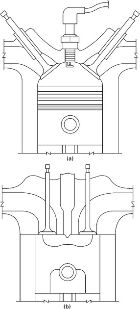
6.1 Common internal combustion engine cylinder designs: (a) spark ignition engine combustion chamber, (b) compression ignition engine combustion chamber.
Although the Otto and Diesel colloquial terms are useful to denote the operating principle of the engine (spark ignition or compression ignition), there is some potential for confusion with the Otto or Diesel ‘textbook’ thermodynamic cycles, commonly taught in introductory thermodynamics courses. In practice, most modern stationary engines, both Otto and Diesel engines, operate with close to constant volume combustion. The air-standard Diesel thermodynamic cycle, characterised by constant pressure combustion, would provide a very poor representation of a modern compression ignition engine.
Both spark ignition and compression ignition engines can use either a two stroke or a four stroke operating cycle, of which the four stroke cycle is by far the most common. Two stroke engines are found in a limited number of applications, interestingly at the outer ends of the power spectrum. For small engines where power density is critical, such as chainsaws or other hand-held tools, two stroke engines are used since they provide higher power output for a given engine size. The two stroke cycle is also used in the largest marine engines, which can be several storeys high and where each cylinder has a power output in the megawatt range. However, since the four stroke cycle provides superior performance in most applications between these extremes, only four stroke engines will be discussed here.
Often, engines for CHP systems are based on existing engine models from, for example, portable power generators or automotive engines. Using existing, mass-produced designs and converting them to CHP operation can clearly reduce cost significantly but is, as will be argued below, not necessarily the best solution to obtain optimum performance. Particularly for the micro-CHP size range (1-5 kW), most existing engines are aimed for transport or similar applications, where low weight and small size are essential and fuel efficiency is less critical.
6.2.1 Basic design considerations
An engine designer faces a number of performance requirements, the most important being good fuel efficiency, high power density, and low exhaust gas emissions levels. In a stationary system, efficiency and emissions will be of highest importance, with the requirements for high power density being somewhat relaxed compared to, for example, a car engine. Some of the fundamental design variables at hand are: design speed, number of cylinders, cylinder bore, stroke length and compression ratio. These parameters provide the basic design outline of the engine, and their influence will be discussed briefly here.
Figure 6.2 shows the significant influence of the compression ratio on the cycle efficiency. A high compression ratio is therefore desirable. However, in practice it is limited by the fuel knock limit (in spark ignition engines), metallurgical limits (since high compression leads to high in-cylinder gas pressures), and heat losses and the formation of temperature-dependent emissions (since high compression leads to high gas temperatures). Also shown are typical fuel efficiency ranges for small (~5 kW) spark ignition (petrol) and compression ignition (Diesel) engines. (Note that the actual efficiency obtained from a real engine depends on numerous other factors in addition to compression ratio, and this is for illustration only.) Worth noticing is the significant potential for efficiency improvement in current engines compared to the theoretical limit (the ideal cycle). The main factors limiting efficiency include mechanical friction, heat losses to the combustion chamber surface, and deviations from the ideal cycle (including volume change during combustion).1
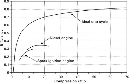
6.2 Ideal (air standard) Otto cycle efficiency and typical fuel efficiencies for small-scale internal combustion engines for micro- CHP systems.
In addition to the compression ratio, the design of the cylinder and combustion chamber are key variables. Typically, approximately 15-20% of the fuel energy is lost to in-cylinder heat transfer, and the combustion chamber should be designed to minimise these losses. Engines which require high power densities typically have low stroke-to-bore ratios, i.e. a short stroke in relation to the piston diameter and the swept volume. For example, a Honda CB1000R motorcycle has a stroke-to-bore ratio of 0.73; a VW Golf 1.6 engine has a stroke-to-bore ratio of 0.96. A short stroke allows high speed operation (see the next paragraph), and thereby high power output, but gives a less compact combustion chamber (at piston top dead centre, the combustion chamber has the shape of a flat disc). This penalises efficiency due to the surface area of the combustion chamber being large in relation to its volume, in turn giving high heat transfer losses. For this reason, engines optimised for high efficiency typically use a higher stroke-to-bore ratio, which gives a more compact combustion chamber with a more favourable volume to surface area ratio. For example, a Volvo TAD1240 300 kW diesel generator set has a stroke-to-bore ratio of 1.15; large marine engines can have stroke-to-bore ratios of up to 4.
The design speed of the engine relates directly to the power output, and thereby the power density, of the engine since it dictates the number of power strokes carried out per unit of time. In the extreme case, material loads (on crank system bearings, piston rings, valves, etc.) limit the maximum speed of the engine. However, frictional losses and gas flow losses scale over- proportionally with the speed, and the trade-off between speed and energy losses is what effectively determines the design speed. In practice, the mean piston speed2 of an engine is the more important variable. Automotive-type engines have maximum mean piston speeds of around 15 m/s, whereas high-performance motorcycle or racing engines can reach above 20 m/s (the Honda CB1000R motorcycle engine has a mean piston speed of 20 m/s at full speed). Engines used for power generation or marine propulsion typically have mean piston speeds around 7-9 m/s. Hence, in order to minimise the friction and the flow losses during the gas exchange stroke (engine breathing losses) in applications where power density is not critical, one would choose a low mean piston speed.
As can be seen, a number of interrelated design variables influence engine performance. However, one important trade-off in the initial design stage is that between engine power density and fuel efficiency. If a penalty in power-to-weight ratio can be accepted, which is often the case in stationary systems, an engine can be designed for optimal fuel efficiency by adopting a longer stroke and lower mean piston speed. For this reason, one would expect better performance from an engine purpose-designed for a CHP system compared to one adapted from, for example, an automotive engine. It should be noted that this is a simplified representation of a complex, multivariable optimisation problem; for a more detailed discussion on these aspects, the reader can refer to Heywood (1988) or Stone (1999).
6.2.2 Spark ignition engines: specific aspects
In spark ignition engines, the combustion process is governed by the flame propagation in the compressed charge. As the piston approaches top dead centre, a spark plug ignites the charge near the centre of the combustion chamber, and the flame spreads towards the outer regions of the combustion space.
As the engine compression ratio dictates the end-of-compression charge temperature, the maximum compression ratio that can be used in spark ignition engines is fundamentally limited by the resistance to self-ignition (knock resistance) of the fuel-air mixture. Engine knock is the phenomenon where the fuel-air mixture that is not yet reached by the flame front ignites spontaneously due to the high pressure from the compression and initial stages of combustion. Such self-ignition gives a violent pressure rise which can produce very high peak pressures, and thereby high mechanical loads on the engine, in particular on the piston rings. To avoid knock when using standard fuels, most commercial spark ignition engines use compression ratios of around 10.
Spark ignition engines used in micro-CHP systems most often run on natural gas, due to its low cost, high availability and well-developed supply infrastructure. Such engines can also run on a range of different fuels, including standard petrol fuel, hydrogen (H2), landfill or anaerobic digester gas, syngas from biomass gasification, etc. This is, however, less common in small- and micro-CHP plants due to cost and/or fuel quality issues. Alcohol fuels, such as methanol and ethanol, are also attractive options for use in spark ignition engines due to their favourable combustion properties (high knock resistance) and the possibility of production from bio-crops, but these have not yet seen widespread use in micro-CHP systems.
The performance of a spark ignition engine depends heavily on the fuel properties, in particular the flame speed. A high flame speed is desirable, in order to provide a rapid, close to constant volume combustion and for operational stability. The flame speed depends on the fuel type, but also on the fuel-air ratio (the richness of the mixture) and on the in-cylinder conditions. For hydrocarbon fuels, the highest flame speed is around stoichiometric conditions; operation with very lean mixtures may lead to penalties in fuel efficiency due to reduced flame speed and poor ignition qualities. The same may be the case for low-quality fuels, such as syngas or landfill gas, which have high fractions of inert species such as N2 or CO2. One option to enhance the combustion and improve performance is to increase the gas velocities and turbulence in the combustion chamber. The flame speed depends heavily on the turbulence levels in the charge, and the gas flow fields in the cylinder are therefore usually optimised through careful design of the ports, valves and combustion chamber. Also, the use of a compact combustion chamber reduces the required flame travel distance, therefore giving a more rapid combustion and improving performance.
The main emissions from spark ignition engines are nitrogen oxides (NOx), carbon monoxide (CO), and unburnt hydrocarbons (HC). One challenge in pre-mixed engines is that the (homogeneous) fuel-air mixture will distribute evenly throughout the combustion chamber. This includes crevices, in which the mixture may be cooled down such that it cannot burn efficiently, or the flame cannot reach (the flame is quenched). This leads to incomplete combustion and increased emissions of unburned hydrocarbons and carbon monoxide, as well as efficiency reductions since part of the fuel energy is not utilised.
The three-way catalyst has become the industry standard for reducing spark ignition engine exhaust gas emissions, and is widely used, particularly in automotive engines. It can provide reduction of all three major emissions species, NOx, CO, and HC, within a single unit. However, in order to operate efficiently, it requires stoichiometric engine operation, i.e. no excess oxygen in the exhaust gas, and it can therefore not be used with lean-burn engines. To ensure efficient catalyst operation, the engine fuel-air ratio must therefore be controlled accurately within a narrow range, and closed loop control of the fuel injection rate is required. This is achieved by using an oxygen sensor at the engine exhaust outlet to adjust the fuel injection rate to obtain stoichiometric conditions. For engines operating primarily in steady state, such as those found in CHP systems, very efficient catalyst operation can be achieved, with above 90% reduction for all three species. Transient engine operation (i.e. load and speed variations) reduces the efficiency of the three-way catalyst somewhat due to difficulty in maintaining a steady fuel-air ratio.
6.2.3 Compression ignition engines: specific aspects
Compression ignition (Diesel) engine operation is fundamentally different from that of spark ignited engines in that the fuel is injected after compression and self-ignites due to the high gas temperature in the combustion chamber. This eliminates the problem of knock, since only pure air is present in the cylinder during the compression stroke, and therefore allows significantly higher compression ratios to be used. The compression ratio in Diesel engines is limited by the pressure and temperature loads on the cylinder structure, and by the formation of temperature-dependent emissions at high combustion temperatures.
Compression ignition engines can use a range of fuels, including standard diesel fuel, heavy fuel oils, biodiesel and vegetable oils. However, the engine performance depends heavily on the quality of the fuel. Requirements for Diesel engine fuels include good ignition and combustion properties, in order to avoid excessive ignition delays and poor combustion efficiency, but also good handling properties, in particular a viscosity suitable for efficient supply through the engine injection system. The latter has been a challenge with many fuels aimed to replace standard (fossil) diesel, such as bio-oils. For these fuels, pre-processing and the use of additives are required to ensure stable properties under varying temperatures and good injection properties. In the marine industry, this has long been the case with low-quality heavy fuel oils requiring thermal viscosity control before being fed to the engine.
As auto-ignition of the injected fuel is required, the fuel must, unlike fuels for spark ignition engines, have good self-ignition properties. Unlike the flame propagation process in spark ignition engines, Diesel combustion rate is governed by diffusion combustion, and the availability of oxygen in the vicinity of the fuel sprays is critical. The properties of the fuel injector determine the spray characteristics and therefore play a key role in the performance of the engine. Moreover, the fuel must have good spray and atomisation properties, to ensure efficient combustion and to avoid excessive emissions formation. High levels of in-cylinder gas motion increases fuel-air mixing and improves performance, and Diesel engines therefore often use bowl-in-piston combustion chamber designs, which enhance gas velocities significantly by forcing the air charge rapidly into the bowl at the end of the compression stroke (this is known as squish).
Since the fuel and air is mixed in the cylinder and over a very short time, utilisation of all the oxygen in the intake air is not possible. Diesel engines therefore always operate lean of stoichiometric, i.e. with an excess of air. However, due to the higher compression ratios used, and the resulting higher temperature levels, the formation of temperature-dependent emissions, most notably nitrogen oxides, in Diesel engines is comparable to that of spark ignition engines. (The exact NOx levels can vary significantly in both engine types and depend heavily on operational parameters such as injection/ignition timing.) Emissions of CO and HC are negligible in Diesel engines; however, particulates emissions represent a major challenge. Particulate matter, or soot, poses significant health risks, and is a particular problem with fuels having poor ignition and combustion characteristics, such as bio-oils. Particulate emissions comprise complex hydrocarbons that have not been fully oxidised, and can be reduced by increasing the combustion temperatures, for example through advancing the start of injection. However, while this increases the oxidation of soot particles, the higher temperatures lead to increased NOx formation, and also influences fuel efficiency, hence there is a trade-off. (This Catch-22-like situation, that measures to reduce particulates emissions tends to increase NOx, and vice versa, is known as ‘the Diesel dilemma’.)
Both NOx and particulate emissions are formed in the fuel spray in Diesel engines, and the injection properties therefore have very high influence on the emissions. Much research effort is going into the improvement of fuel injection systems, and there is a clear trend towards higher injection pressures to give a finer fuel spray and better fuel break-up and atomisation. Further strategies, which have been made possible with modern, high-speed and electronically controlled injection systems, include multiple injections and rate shaping of the injector flow. External means for reducing Diesel engine emissions include reduction catalysts for NOx, which are not normally used in small-scale systems due to high costs, and particulate filters, which are increasingly being used in automotive and other small-scale systems. The Diesel version of the SenerTec Dachs micro-CHP system, described in more detail below, is fitted with a particulate filter.
6.3 Engine operating characteristics and performance
Electrical efficiency is of key importance in all heat engines. However, for use in micro-CHP systems, effective recovery of waste heat is also critical in order to provide a good total utilisation of the fuel energy. Further, the operational flexibility of the plant is of high importance, in particular whether efficient part load operation is possible to meet varying load demands.
6.3.1 Energy balance, efficiency and heat recovery
As a rule of thumb, the energy supplied to an internal combustion engine through the fuel can be divided into three parts: approximately one-third is converted into mechanical work; approximately one-third is lost as heat in the exhaust gases; and approximately one-third is lost as friction and heat losses within the engine. Most of the latter is carried away as heat by the cooling water circuit and lubrication oil cooler (if applicable), but a part of this energy is lost as radiation, convection and other non-recoverable energy losses.
The ratio of mechanical output to the fuel input energy is known as engine efficiency. For many applications this is the only performance parameter of interest, as the mechanical work is often the only energy that is utilised (the exhaust gas and cooling heat is simply dumped). While in CHP systems heat losses are also utilised, engine efficiency is still of paramount importance, since the electrical output that can be fed back to the grid essentially determines the economic viability of an investment in a CHP system over a conventional boiler. The efficiency that can be achieved in internal combustion engines varies significantly with engine size, design, fuel type and operational conditions. The 5.5 kW Dachs micro-CHP unit, discussed in more detail below, has an electrical efficiency of 27-30%, while the 4.7 kW ecopower unit achieves 24% efficiency. Notably, internal combustion engines are suitable for scaling down to small sizes without excessive efficiency penalties; the Honda Freewatt unit achieves an efficiency of 22% at 1.2 kW electrical output. For comparison, Diesel engine or spark ignited natural gas-based generator sets with 300-500 kW output achieve efficiencies around 40%; the largest low-speed marine propulsion engines are the most efficient internal combustion engines and can achieve 50% efficiency.
Figure 6.3 shows a typical configuration of an internal combustion engine-based CHP system. Recovery of heat from the engine cooling system can be achieved by adapting the heat exchanger in the cooling circuit (through which the cooling heat is otherwise dumped). The cooling water has a temperature of 85-95 °C, and this is maintained nearly constant over the load range by control of the cooling water flow rate. If the engine has a separate lubrication oil cooler, recovery of this heat can be carried out in series with the cooling water; the lubrication oil typically has a temperature slightly lower than that of the cooling water circuit. In larger systems, turbocharger cooling can also provide a small amount of heat recovery.
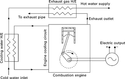
Recovery of exhaust gas heat is carried out using an exhaust gas heat exchanger, and heat can be recovered as hot water or low-pressure steam at 100-120 °C. The exhaust gas temperature can vary significantly over the engine load range, from above 600 °C at full load down to around 300 °C at idle. The temperature even at low loads is sufficiently high for effective heat utilisation; however, these temperature variations must be taken into account when designing the energy recovery system. Condensing heat exchangers can be utilised to recover the latent heat in the steam in the exhaust stream. However, the use of condensing boilers is normally limited to natural gas- fired systems due to problems of corrosion when using other fuels.
Figure 6.4 shows a typical breakdown of the energy balance in an internal combustion engine over the load range. It can be seen that the engine efficiency, i.e. the fraction of mechanical output to the fuel input energy, drops rapidly below approximately 50% load; this is a typical characteristic of internal combustion engines. Over the load range, there is a relatively stable fraction of non-recoverable losses of between 5 and 10% of the fuel input energy. At idling (0% load), there is no mechanical output and fuel is supplied merely to overcome internal friction and keep the engine running. Most of this friction work is dissipated as heat through the cooling system. As the load increases, the engine efficiency improves and the fraction of energy lost to the exhaust and cooling system is reduced. At full load, the energy distribution is approximately 37% mechanical work, 33% exhaust heat, and 21% cooling system heat.
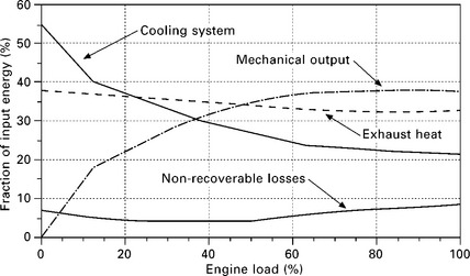
6.4 Typical energy balance in an internal combustion engine based CHP system (Wilbur 1985).
6.3.2 Operational optimisation and load control
On commissioning, the operational strategy of the engine must be established. While the major engine design variables are fixed, some flexibility exists in the possibility to adjust operating parameters, most importantly fuel injection rate and ignition or start-of-injection timing. Modern engines use an electronic control unit (ECU) to control operational variables. One advantage of this is that the settings can be adjusted according to the operating conditions, such that the performance of the engine is optimised for any given speed or load level.
Internal combustion engine-based generator systems commonly run at constant speed, allowing them to supply alternating current at the required frequency directly to the grid. To allow varying speed operation, a frequency converter and power electronics are usually required in order to condition the electric power output. This adds cost and introduces losses in the electric circuit, but gives the flexibility of allowing the engine power output to be adjusted over the full load range.
Figure 6.5 shows a typical performance map for a spark ignition engine. (Engine torque is shown as brake mean effective pressure (bmep), which is a common measure for ‘specific torque’ and proportional to the shaft torque.) The power output is the product of speed and torque, hence a load change can be effectuated through a torque change at constant speed, a speed change at constant torque, or a change in both variables. superimposed on the efficiency map are two lines of constant load, where Load 1 at 2500 rpm illustrates the design operating point, and Load 2 represents an approximate 40% load reduction from Load 1.
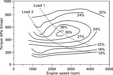
6.5 Typical performance map for a spark ignition engine (Heywood 1988).
It can be seen that changes in torque have a large influence on engine efficiency, and it is clear that, from the combustion engine perspective, having a constant speed engine is the least desirable option if operation over a range of loads is required. (Consider changing from Load 1 to Load 2 at constant speed.) An imaginary constant-torque engine with variable speed would be preferred, since the engine efficiency is less sensitive to speed changes. Clearly, the ability to vary both load and speed both increases the load range available and provides more flexibility and operational optimisation possibilities. It should, however, also be noted that one may not have complete freedom to choose any combination of torque and speed for a given load, since this also depends on the electric machine being able to utilise the output efficiently.
While the load and/or speed of the engine is controlled through the fuelling rate, the spark timing, or start-of-injection timing in Diesel engines, is used exclusively for operation optimisation purposes. At any operating point, i.e. for any given speed and load, there is an optimum ignition/injection timing which will give highest fuel efficiency (e.g. 15 crank angle degrees before top dead centre). In practice, the ignition/injection timing is retarded (delayed) slightly compared to this optimum value, in order to reduce NOx formation. Even small variations in the ignition timing and the start of combustion have large influence on the peak combustion temperatures, and therefore on NOx formation. Retarding the ignition/injection (e.g. by 5 crank angle degrees) produces major reductions in NOx formation while giving only a modest penalty in fuel efficiency. (Due to the large influence of engine tuning on NOx formation, a single engine model can be supplied in standard mode and in low-NOx mode, the only difference being the software settings.)
6.4 Installation and practical aspects
Unlike large-scale systems, small- and micro-CHP systems are usually supplied in a ready-to-install package, requiring only the connection of fuel and exhaust lines, electrical grid connection, and heating circuit connection. In many cases, a micro-CHP system can directly replace an existing boiler in a system; however, some limitations exist related to the installation. Due to the noise and vibration from an engine system, as well as the relatively large size of the units, internal combustion engine-based micro-CHP systems are generally not intended for installation inside the living area of domestic residences. Further, if the CHP unit is replacing a conventional boiler, the increased fuel and exhaust flows for a constant heat output (since the CHP system produces electricity in addition to heat) must be taken into account.
In the integration of the CHP unit in the building heating system, it is critical that the return temperature from the heating circuit be below that prescribed by the manufacturer. Too high a return temperature may lead to thermal overload in the combustion engine, which may be critical for the engine. The maximum allowable return temperature for internal combustion engine-based micro-CHP systems is typically 60-70 °C. Also, in order to maximise fuel utilisation, in particular when using a condensing exhaust heat exchanger, a sufficiently low return temperature is required.
6.4.1 Electrical connection
A three-phase (400 V) electrical connection is commonly required, but smaller systems (around 1 kWel) can also use single phase (230 V) connections. The micro-CHP system is usually connected in parallel with other consumers, so that the net difference in usage and production at any time can be supplied back to the grid. Although the net electrical usage can be registered by a standard meter installed by the utility, a separate meter for supplied electrical energy is commonly installed to take into account differences in electricity prices for usage and supply as well as subsidies for micro-CHP generation. The electrical connection always includes an (automatic) emergency switch allowing the CHP system to be taken off the grid in case of, for example, maintenance work by the utility, in order to avoid individual CHP units continuing to supply power to the grid in such a case.
Additional power electronics can be installed to allow operation of the CHP system in stand-alone mode as an emergency power supply. If there is a power outage, both the CHP system and consumers will be disconnected from the grid and the CHP unit then re-started to supply off-grid electric power. Both the Dachs and ecopower micro-CHP units (described below) can be supplied with such a system.
6.4.2 Operational control
Since the output of a CHP system will only rarely be able to match exactly the electrical and heating demand in a building, an operational scheme must be decided upon. There are three options: heat-led operation, electricity-led operation, or a combination of the two.
In the most commonly used heat-led mode, the CHP system will be controlled to meet the heating demand in the installation, much like a conventional boiler. The electricity produced will be fed to local consumers or supplied to the grid according to the production rate and independent of the local electricity usage. Heat-led operation is favoured in most cases due to the flexibility of the electrical supply; any excess electric energy from the CHP system can be fed back to the grid at any time, hence no energy is ‘lost’. in heat-led operation, the CHP system will be designed to meet a given minimum heating load, and, depending on the plant, a supplementary boiler or thermal energy storage can be used to meet demand peaks and to allow stable and continuous operation of the CHP system. In particular for small applications, a well-matched hot water storage will allow better utilisation of the CHP unit. By allowing the CHP system to charge the heat storage at times of low demand (such as night time), the system can run in steady state mode for most of its operational time and does not need to follow the dynamically changing building heat demand.
In electricity-led operation, the CHP system is controlled to meet the building electrical power demand at any time. This type of operation may be advantageous in applications with periods of high electrical loads, and where peak-load electric energy is more expensive. Under electricity-led operation, efficient utilisation of the produced heat becomes critical in order to maintain good total system efficiency. The use of heat storage is common if the base heat load is lower than the production rate, in order to avoid dumping heat energy.
A combination of heat-led and electricity-led operation is also possible, and, if matched to a building’s energy demands, may give a better total efficiency than one of the above alone. Optimal operation of a CHP system is a highly complex problem, since it depends on the efficiency map of the heat engine, the fuel price, the electricity purchase and feedback tariffs (both of which often vary over the course of a day), and the electrical and heat demand profiles of the building. Internal combustion engine-based micro- CHP systems allowing variable speed operation, such as the ecopower unit described below, can provide efficient generation with variable electrical and heat output, and can therefore provide valuable flexibility for operational control and optimisation. Constant-power units, such as the Dachs, may require energy storage in order to provide good total efficiency in plants with highly varying load demands.
6.4.3 Maintenance, reliability and availability
Being a mature and well-tested technology, internal combustion engine systems are generally reliable, but require regular maintenance and therefore regular scheduled outages. Despite this, availability levels of above 95% are commonly reported for stationary engine systems.
One advantage of internal combustion engines used in stationary power generation is the highly favourable operating regime. Engines used in CHP systems run under stable conditions, often at constant load and speed, and over long periods of time. This is a major advantage in terms of maintenance, wear rates and reliability compared to, for example, automotive engines, which operate under constantly varying load demands, speed variations and with frequent cold starts. For this reason, the lifetime of a stationary engine is many times that of one used in a vehicle.
Regular engine maintenance includes changing of lubrication oil, filters, engine coolant, spark plugs, etc. Recommended maintenance intervals are typically: every 3500-4000 h for natural gas fuelled engines; every 2700 h for operation on heating oil; every 1400 h for biodiesel operation; and every 750-1000 h for engines running on vegetable oils (Thomas, 2007). Some manufacturers have service plans which include major overhauls after (typically) between 15 000 and 40 000 running hours, and this can include changing piston and piston rings, fuel injectors, bearings, seals, etc.
6.5 Commercially available units
This final section presents an overview of some commercially available internal combustion engine-based micro-CHP systems. some reported design and performance data will be presented; however, it should be noted that detailed information is protected industrial intellectual property and is therefore not publicly available.
6.5.1 SenerTec Dachs
German company SenerTec is the market leader for micro-scale CHP systems in Europe, having installed more than 20 000 units of their Dachs micro-CHP system, shown in fig. 6.6. While the system is suitable for larger domestic residences, it is believed that the main market is larger buildings with high heating demands, such as hotels, schools, etc. To meet any required energy demand, the manufacturer can supply systems comprising several units operating in parallel.

6.6 SenerTec Dachs micro-CHP unit. (Illustrations courtesy of SenerTec Kraft-Wä rme-Energiesysteme GmbH (SenerTec, 2010). Reprinted with permission.)
The Dachs can be supplied for several different fuels, including natural gas, propane, heating oil, biodiesel, and rapeseed oil, of which the natural gas version is the most sold. In addition to models for different fuels, SenerTec also supplies a range of accessories, including versions that can supply emergency power in case of a power outage, as well as systems aimed for stand-alone power supply in remote applications. Table 6.1 shows technical data for some of the Dachs models. The different versions are based around the same basic structure, with engine modifications implemented to adapt the system to the different fuels.
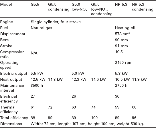
Heat recovery is carried out using a combined cooling system and exhaust gas heat exchanger. The exhaust gas temperature at the system outlet is 150 °C in the standard versions; however, a condensing heat exchanger can be supplied with the unit. The condensing heat exchanger gives an additional 1.4—2.3 kW thermal output by cooling the exhaust to 55 °C, thereby significantly increasing the thermal and total efficiency of the unit.
Fuel utilisation is generally good for all versions, with electrical efficiency above 26%. Independent tests have confirmed the efficiency values: Thomas (2008) reported that 28% electrical efficiency and 89% total efficiency were achieved for the G5.5 model in laboratory tests for a German environmental certification (i.e. slightly exceeding the performance claimed by the manufacturer).
Maintenance requirements for the system vary depending on the fuel used, with recommended service intervals every 3500 h with natural gas down to every 1400 h for the biodiesel and rapeseed oil models. With regular maintenance, the design service life of the unit is 80 000 h.
The Diesel engine versions (HR models) of the Dachs are fitted with a soot filter to reduce particulates emissions. The natural gas fuelled models are lean burn and therefore, unlike e.g. the ecopower unit described below, do not use a three-way catalyst. An emissions comparison between these two systems can be found below.
There are only minor differences in price for the natural gas and heating oil models: at the time of writing, the recommended retail price from SenerTec is around €21,000, with the condensing heat exchanger costing an additional €2000. For other models, such as that for vegetable oil fuel or for off-grid power generation, the prices are somewhat higher.
6.5.2 PowerPlus Technologies ecopower
The ecopower micro-CHP system is developed by PowerPlus Technologies, a subsidiary of Vaillant, one of Europe’s largest boiler manufacturers. With 4.7 kW electrical output the unit is similar to the Dachs, however, with one significant difference in that the ecopower provides variable electric output, from 4.7 kW down to 1.3 kW. This is achieved through engine speed control, and a frequency converter is implemented to condition the power output for supply to the grid.
Table 6.2 shows the basic design data for the ecopower micro-CHP unit. The price of the unit is similar to the Dachs, at approximately €20 000. The ecopower includes a condensing heat exchanger in the standard version, and achieves electrical and total efficiencies of 24.7% and 88.9%, respectively, at full load (Thomas, 2008). The gas engine is designed for stoichiometric operation and fitted with a three-way catalyst, which gives very low exhaust gas emissions levels at steady state operation. Thomas (2008) notes that the emissions are somewhat higher during transients.
Table 6.2
Ecopower micro-CHP unit design and operational data (Thomas, 2007; PowerPlus Technologies, 2010)
| Engine | Single cylinder, four stroke, spark ignition |
| Fuel | Natural gas or propane |
| Displacement | 272 cm3 |
| Bore | 73 mm |
| Stroke | 65 mm |
| Compression ratio | 12.8 |
| Operating speed | 1200-3600 rpm |
| Electric output | 1.3-4.7 kW |
| Heat output | 4.0-12.5 kW |
| Design service life | 40 000 h (80 000 h with major overhaul) |
| Maintenance interval | 4000 h (or at least yearly) |
| Dimensions | Height 108 cm, width 76 cm, depth 137 cm, weight 395 kg. |
Thomas (2007) presented test results for the ecopower; these are summarised in Fig. 6.7. It can be seen that excellent part load efficiencies are achieved, with electrical efficiency of above 20% over the full load range. The same is the case for the thermal efficiency, and the wide load range of the unit makes ecopower a very flexible option in plants where varying output is desired or required.
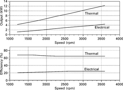
6.7 PowerPlus Technologies ecopower CHP unit performance data (Thomas, 2007).
In his comprehensive benchmark testing of different micro-CHP systems, Thomas (2007) further measured exhaust gas emissions in the ecopower and also compared these to measurements taken from the SenerTec Dachs. The ecopower produced CO emissions levels of 0.1 mg/Nm3 and NOx emissions levels of 8.4 mg/Nm3 NOx (at 5% O2); these are very low and show the effectiveness of the three-way catalyst. For the Dachs, which operate in lean burn mode and without a catalyst, the measurements were 0 mg/Nm3 CO and 500-600 mg/Nm3 NOx. It should, however, be noted that these tests were done with the standard, natural gas fuelled Dachs model (G5.5). According to senerTec, the low-NOx model (G5.0) achieves a 50% reduction in NOx compared to this, but at the cost of slightly lower electrical efficiency, as shown above.
6.5.3 Honda Ecowill/Freewatt
The Honda Ecowill micro-CHP unit has been available for a number of years in Japan, and sales have reached more than 50 000 units. It is also available in USA, where it is marketed under the name Freewatt. The US version is based around the same engine but has minor design differences. The system is currently being introduced to Europe in a collaboration between Honda and Vaillant. The electric power output is 1 kW (1.2 kW in the USA), and it is therefore suitable for smaller dwellings than the Dachs or the ecowill. The system is based around a single-cylinder, water-cooled four stroke engine with 163 cm3 displacement, running on natural gas. The thermal output is 3.25 kW, and system efficiencies are 22.5% electrical and 85.5% total.
The engine is configured for stoichiometric operation and the system uses a three-way catalyst to control emissions. Very low emissions levels can therefore be expected; however, detailed information from the manufacturer or independent tests are not available. Service is required only every 6000 hours (Slowe, 2006). The unit is 640 mm wide, 380 mm deep and 940 mm high, and weighs 83 kg. Installation cost is approximately £5,600 (Harrison, 2010).
6.6 Conclusions
Engines for micro-CHP systems will without question continue to develop into its own specialist niche within the massive landscape of internal combustion engine systems. From the first academic studies of internal combustion engine-based micro-CHP which typically used converted engines from other applications, we are now seeing purpose-designed engines being developed for such systems.
As this technology becomes more mature and more widely used, the performance of these engines will likely continue to improve. Internal combustion engine-based micro-CHP systems can provide efficient and reliable power generation with low installation costs, and if the problems of vibration and noise can be overcome, such systems have the potential to take a large share of the micro-CHP market.
6.7 References
Harrison, J. Micro combined heat and power web site. http://www.microchap.info, 2010.
Heywood, J.B. Internal combustion engine fundamentals. Maidenhead: McGraw-Hill; 1988.
PowerPlus Technologies. Company web site. http://www.ecopower.de, 2010.
Slowe, J. Micro-CHP: Global industry status and commercial prospects. 23rd World Gas Conference, Amsterdam. 2006.
Stone, R. Introduction to internal combustion engines. New York: MacMillian; 1999.
Thomas, B. Mini-Blockheizkraftwerke. Würzburg: Vogel Buchverlag; 2007.
Thomas, B. Benchmark testing of Micro-CHP units. Applied Thermal Engineering. 2008; 28:2049–2054.
Wilbur, L.C. Handbook of Energy Systems Engineering. Chichester: Wiley; 1985.
1One concept with large potential and currently receiving significant research attention is the lean-burn, homogeneous charge compression ignition (HCCI) concept. This is a pre-mixed engine in which the charge is compressed until self-ignition, giving very fast and close to constant volume combustion. The use of a lean charge, i.e. with an excess of air compared to that necessary for combustion, reduces peak temperatures, and thereby heat losses and emissions formation. However, problems in controlling the ignition timing have prevented this concept from seeing commercial application.
2Mean piston speed, vp, is a function of engine speed, N, and stroke length, S, such that vp = 2SN. For example, an engine with 80 mm stroke running at 3000 rpm (50 Hz) has a mean piston speed of 8 m/s.