
Microturbine systems for small combined heat and power (CHP) applications
Abstract:
Microturbines are small-size gas turbines with high potential for distributed energy systems. The chapter discusses the characteristic features of microturbines in combined heat and power (CHP) generation under 100 kWe. It begins by introducing the challenges for the design in the microturbine scale and analyzing the factors that affect the performance in CHP operation. The chapter then describes the types and properties of the main microturbine components and considers operational viewpoints. Finally the chapter presents the current manufacturers and future trends for the microturbine industry.
7.1 Introduction
Microturbines are small-size gas turbines. They have been developed based on the principles of larger industrial systems, but using development results in the automotive turbocharger and gas turbine research as well as solutions in auxiliary power units. After the development with automotive gas turbines stalled, the idea of using microturbines for power and CHP applications was introduced in the 1990s and stronger commercial products have been available since 2000.
A microturbine cycle in the simplest construction comprises a compressor, combustion chamber, turbine and generator. Air is compressed in the compressor to a higher pressure (3-5 bars), fuel is burnt in the combustion chamber using part of the compressed air and the combustion gases enter the turbine (typically at 900-950 °C). The gases are expanded in the turbine, which produces more power than the compressor consumes. This surplus power is converted to shaft power to drive the generator (Fig. 7.1(a)). The gases exhausting from the turbine can be at high temperature. It is advantageous from the fuel-to-power conversion efficiency point of view to use a recuperator where heat from the combustion gases is transferred to the air before combustion (Fig. 7.1(b)). Before discharging the gases to the atmosphere, their thermal energy is recovered for external heating purposes in CHP operation. The current microturbines apply recuperated configuration and generate power at approximately 30% efficiency, but without the recuperator the efficiency would be only half of this. In CHP the total efficiency of heat and power generation is typically in the range of 75-85% depending on the application.
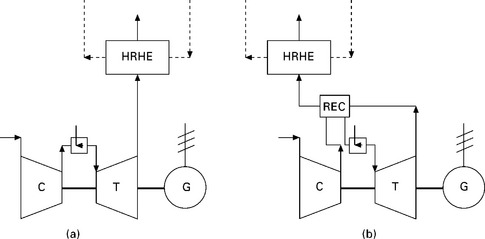
7.1 Flow diagram of (a) simple gas turbine cycle and (b) recuperative cycle. C is compressor, T turbine, G generator, REC recuperator and HRHE heat recovery heat exchanger.
The simplest arrangement is to have the compressor, turbine and generator on a single shaft. In the two-shaft arrangement the first turbine drives the compressor on one shaft, and the second turbine powers the generator on another. The single-shaft type dominates the market and is also the focus of this chapter. We have chosen to use 100 kW of produced electricity as the upper limit of the microturbine power range. Some define it as below 1000 kW (Pritchard, 2002), some below 100 kW and even below 15 kW (Dong et al., 2009; Malmquist, 2006).
The target applications in the industry are microturbines that produce the electricity and heat required for the processes or water heating. In hospitals, office and factory buildings the microturbine gives electricity as well as summer absorption chilling and winter heating. In some electricity critical manufacturing processes, microturbines may provide the primary power with UPS battery backup (Soares, 2007).
Microturbines are well suited for distributed generation applications due to their flexibility in connection methods. In distributed generation reliable operation is important since these locations may be remote from the grid and in case of failures the loss of power may have large financial consequences (EEA, 2008). The total equipment costs for microturbine-based CHP applications (producing hot water) are around $1600-1700/kWe (EEA, 2008). The fuel cost can be as high as 75% of all costs incurred during the operational lifetime, while the other costs comprise mainly service and capital costs (Boyce, 2006). The overall production of microturbines (below 100 kWe) during 2010-2015 is predicted to be in the range of 1000-1500 units (Soares, 2008).
7.1.1 Gas turbine development
Gas turbines were developed at the end of the nineteenth century, but due to the low unit efficiencies and elementary combustion technology they did not generate power until the first decades of the twentieth century. The first commercial gas turbines were made in the 1940s and 1950s, but the technological breakthrough came in the 1960s. The gain in efficiency is clearly seen in Fig. 7.2 and it seems that there is no major improvement to be foreseen in the efficiency of the industrial gas turbine.
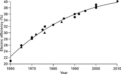
The efficiency increase is due to improvements in the internal flow characteristics in turbines and compressors as well as increases in the turbine inlet temperatures. The polytropic efficiencies have been approaching unity and the turbine inlet temperatures have become closer to that of the combustion process itself. The specific price of the gas turbine unit decreases with increasing size. This enables investment in more complex systems and using more advanced materials. As a result, the efficiencies of the gas turbines also increase with increasing size (Fig. 7.3).
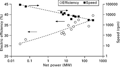
7.3 Power and efficiency of current gas turbines over 1 MW (Siemens, 2010) and below (Capstone, 2010a).
7.1.2 General challenges with microturbine scale
The availability of commercial microturbines is scarce as the manufacturing capacity has not reached the economical requirements. It is therefore necessary to contemplate the reasons for this.
Volume
Industrial gas turbines are serving municipalities or factories and are very large in size (power output currently up to 340 MW), which also contributes to high efficiency as the fluid paths are relatively large. Also, the pressure of the combustion is quite high, usually between 20 and 40 bars leading to pressure and expansion ratios of the same magnitude in an open gas turbine cycle. The through-flow velocity is kept constant in all the stages in the axial compressor. This works in favour of the designer as the stages can be designed on similar principles, but it also means that the channel area must decrease with the increasing density of the fluid.
In the industrial gas turbines one can find the narrowest flow paths in the last stage of the axial compressor. The blade heights vary from hundreds to some ten millimeters as the gas turbine power decreases from hundreds to a few megawatts. If the power is less than 100 kilowatts this analogy makes the last stage blade to be only a few millimeters. The manufacture of such small parts is possible, but the ratio between the flow channel area and the circumference will become very small and thus the efficiency will be low.
The gaps between the rotating wheels and the stationary casing are usually sealed up with contactless seals, such as labyrinth seals, to reduce mechanical losses and ensure a long life. Therefore, there always exist small paths where the air can leak out. The smaller the turbomachinery, the relatively larger the gaps become.
Speed
Turbomachine design is governed by defining the pressure ratio, volume flow and angular speed. The single machine element, a centrifugal or an axial stage is defined by its specific speed NS
where ω is angular speed (rad/s), N is rotational speed (1/s), qv is inlet volume flow (m3/s) and Δhs is stage isentropic enthalpy change (J/kg).
Results of an extensive study on specific speeds for various turbines, compressors and pumps are shown in Fig. 7.4 (Balje, 1981), where the compressor types and contours of constant isentropic efficiency are plotted for single-stage compressors against specific speed and specific diameters Ds. The diagram shows that in order to maintain high efficiency, the specific speed Ns cannot be varied extensively.
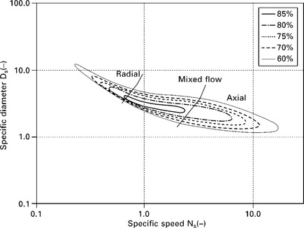
7.4 Efficiency values of single stage compressors. Adapted from Balje (1981).
When the turbomachine is made smaller in size, the work done in the fluid is still the same and the denominator in Equation 7.1 does not change. Instead, the volume flow is smaller with the decreased power and consequently the speed has to be increased. It therefore can be stated for machines with the same pressure ratio that the speed of a turbomachine increases inversely proportionally to the square root of its power. This effect can also be seen in Fig. 7.3.
Efficiency
In principle, there should be no thermodynamic reasons not to have as efficient turbomachinery in the microturbine as at the industrial scale. But we need to use the same fluids and part of the machinery is rotational. From the efficiency point of view, the fluid Reynolds number should be discussed and it is in general defined as

where c is velocity (m/s), d is characteristic length (m) and v is kinematic viscosity (m2/s). There is a critical Reynolds number magnitude of about 2 • 105 above which the viscosity-related losses are constant (Baskharone, 2006). For example, if the Reynolds number related to the impeller blade height and circumferential velocity drops from 2 • 105 to 2 • 104, the efficiency of the centrifugal compressor decreases ten percentage points (Casey, 1985).
The aforementioned challenges in the microturbine scale are summarized in Fig. 7.5, which depicts the dependency of compressor and turbine efficiencies on the microturbine size.
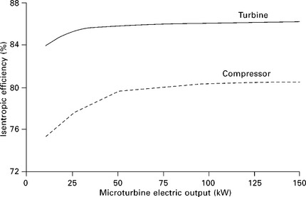
7.5 Effect of microturbine power output on compressor and turbine efficiency (Galanti and Massardo, 2010).
7.2 Cycle performance
All actual gas and microturbines are based on an ideal Brayton (Joule) cycle that contains compression, heat addition, expansion and heat rejection. In the ideal cycle, all these processes take place without loss of energy so they are reversible. The compression and expansion are also adiabatic so that no heat transfer occurs, and hence they are isentropic (entropy remains unchanged). Heat is added to and removed from the cycle by heat transfer so the amount and composition of the working gas remain constant throughout the cycle. An extensive analysis for the ideal Brayton cycle and its variants is given in the classical textbooks of thermodynamics and turbomachinery such as Moran and Shapiro (2010) and Saravanamuttoo et al. (2008).
In the actual microturbines, losses and dissipation of energy occur in each component. The compressor and turbine can be considered adiabatic with high accuracy, but as a result of losses entropy is increased in these processes. Fluid friction causes pressure losses in various components such as combustion chamber, heat exchangers as well as inlet and outlet ducting. The heat is added to the cycle in the combustion chamber by burning fuel in the air flow. As a result, the working gas composition and, to a small degree, its amount change. Typically, microturbines apply the so-called open cycle where the compressor draws ambient air and combustion gases are discharged back to the atmosphere. The interpretation is that the atmosphere completes the series of processes into a cycle. The T-s diagram for the ideal Brayton cycle and actual microturbine cycle with the same maximum temperature is presented in Fig. 7.6(a).
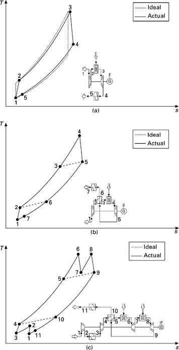
7.6 T-s diagram and flow diagram for (a) ideal Brayton cycle and the actual simple microturbine cycle, (b) actual recuperated cycle and (c) actual intercooled, recuperated and reheated cycle.
The added heat in the combustion chamber is fully available in the form of hot combustion gases. Instead, the heat exchangers where heat is transferred through a separating wall feature a temperature difference between the hotter and colder fluids. Recuperators, heat recovery heat exchangers (for water heating, for instance) and intercoolers are of this type. Mechanical losses are incurred in the rotating shaft (or shafts in a multiple shaft unit) and conversion losses in the generator and power conditioning. The electric output is further decreased by the auxiliary power needs of the control system and possible fuel compressor, for instance. In CHP applications, the heat recovery is implemented after the power cycle. As a result, it affects the electricity generation by increasing the pressure losses in the hot-gas path.
The microturbine configurations that will be considered here are the simple cycle, recuperated cycle, and the cycle with intercooling, recuperation and reheat. All these cycles are of the open type and they generate power and heat. The number of shafts has no relevance in this type of design analysis.
The simple cycle is the most straightforward configuration containing only the compressor, combustion chamber, turbine, generator and heat recovery heat exchanger as the main components (Fig. 7.6(a)). In the simple cycle combustion gases are discharged from the turbine, and consequently from the power cycle, at a high temperature. This contributes to the recoverable heat but penalizes the efficiency of electricity generation. To increase electric efficiency, the standard solution for current microturbines is to use recuperation (Fig. 7.6(b)). In the recuperated cycle the heat of the turbine discharge flow is utilized to pre-heat the compressed air before combustion. This reduces the fuel amount necessary to achieve the desired combustion temperature, but also penalizes power output slightly due to increased pressure losses. The recuperator performance is determined using the term effectiveness (thermal ratio) which is the ratio of the actual heat transfer rate and theoretically maximum rate.
While the recuperated microturbine represents current practice in the microturbine segment, more complex configurations are being developed to boost the performance to new levels and/or create new applications (ATT, 2010). To give an indication of the performance potential, a case that combines intercooling, recuperation and reheating is considered (Fig. 7.6(c)). An intercooler between the compressor stages counteracts the temperature rise, hence reducing the power need for compression. Similarly, an additional combustion chamber between the turbine stages helps to maintain the temperature level, increasing the power output from expansion. Both these methods increase the net output from the unit and when used together with recuperation, electric efficiency too.
In this presentation, four performance parameters have been selected for characterizing the performance of the microturbines in CHP operation: electric efficiency ηe, specific power Psp, total efficiency ηtot, and power-to-heat ratio σ.
Electric efficiency is an established parameter also in CHP operation focusing on the most valuable species of energy, electricity. It is the ratio of the net electric output Pe to fuel input Φf.

Total efficiency (overall energy conversion efficiency) takes into account the useful heat output too, and the efficiency is the ratio of the electric and heat outputs to fuel input.
Fuel input is determined here using the lower heating value (LHV) for the fuel, which does not include the latent heat of condensation of the water vapour in the combustion gases. By using the lower heating value it is thereby assumed that no condensation of water occurs.
The sensible enthalpy hf of the incoming fuel is also taken into account for completeness, although its value is insignificant compared to LHV, especially for liquid and gaseous fuels.
Power-to-heat ratio proportions the products of operation, net electric output and useful heat output. Although it can be determined on the basis of electric and total efficiencies, and therefore brings no additional value, it is a convenient parameter for assessing the applicability of the microturbine for a case with given heat and electricity loads.
Specific power is determined by dividing the net electric output by compressor mass flow.
It characterizes the size of the unit for given power, and is therefore indicative of the price, too. This is especially valid for the recuperated microturbines with expensive gas-to-gas recuperators: a decrease in specific power increases the mass flow through the recuperator, hence increasing its heat transfer rate and price.
Microturbine performance depends mainly on the turbomachinery (compressor and turbine) efficiencies, turbine inlet temperature and compressor delivery pressure, indicated commonly using compressor pressure ratio. While increasing the efficiencies and inlet temperature contribute to the performance unambiguously, the selection of the pressure ratio can be seen more as an optimization task. The optimum depends on the other parameters, but also on the desired criterion.
An analysis will be given on the effect of compressor pressure ratio and turbine inlet temperature on the performance of the selected configurations (simple cycle SC, recuperated cycle RC, and the cycle with intercooling, recuperation and reheat ICRRC). While values for turbine inlet temperatures are typically in the range of 900-950 °C for current microturbines, slightly lower and higher values are also used to indicate their effect on performance. The analysis is based on ISO operating conditions (15 °C, 101.3 kPa, 60%) and using natural gas. The fuel is in practice sulfur-free and therefore the amount of recoverable heat is not limited by the condensation of sulphuric acids. Consequently, the exhaust gas temperature after the heat recovery boiler is selected as low as 70 °C. In the intercooler, the minimum temperature for outlet air is 30 °C. However, the risk of condensation onto the cold surfaces of the air channels is taken into account by using a temperature margin of 10 °C between the air outlet temperature and saturation temperature. The simulation has been performed using commercial heat balance modelling software IPSEpro. Table 7.1 presents the main input values for the simulation, which can be considered typical for the current microturbines. The simulation results are collected in Fig. 7.7.
Table 7.1
Main input values in the simulation, all values in %
| Recuperator effectiveness | 90 |
| Compressor polytropic efficiency | 83 |
| Turbine polytropic efficiency | 84 |
| Mechanical efficiency (shaft) | 98 |
| Electromechanical efficiency (generator and inverter) | 90 |
| Intercooler airside pressure loss | 1 |
| Recuperator airside pressure loss | 1 |
| Combustion chamber pressure loss | 3 |
| Recuperator exhaust gas side pressure loss | 3 |
| Heat recovery heat exchanger pressure loss (gas side) | 1 |
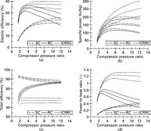
7.7 Effect of compressor pressure ratio on (a) electric efficiency, (b) specific power, (c) total efficiency and (d) power-to-heat ratio for simple cycle (SC), recuperated cycle (RC), and intercooled, recuperated and reheated cycle (ICRRC). The curve parameter is turbine inlet temperature with values of 800, 900 and 1000 °C. Increase in temperature improves all performance parameters.
As Fig. 7.7 shows, an optimum pressure ratio exists to maximize electric efficiency for all configurations. Maximum specific power is attained at a certain pressure ratio too, but it differs from the value for best efficiency. The difference between the values is so high that selecting one as the design basis incorporates compromises with respect to the other. Typically, the performance of the microturbines is optimized for (or near) maximum efficiency. Increase in turbine inlet temperature increases the electric efficiency and specific power as well as their optimum pressure ratios. However, the increase in pressure ratio is moderate except for the electric efficiency of the simple cycle. Also, the curves for efficiency and specific power are flat, and as a consequence, the impact of pressure ratio on performance remains low around the optimum. An exception here is the recuperated cycle with strong decrease in electric efficiency especially at pressure ratios lower than the optimum.
Compared to the simple cycle, recuperation increases the electric efficiency and decreases the optimum pressure ratio considerably. Electric power output decreases mildly due to the pressure losses in the recuperator, thus reducing the specific power output. The intercooled, recuperated and reheated cycle offers the highest electric efficiency among the studied configurations. This is a result of several contributing factors. Intercooling reduces the compression power need while additional heat supply increases turbine power yield. As a result, the net output of the unit increases. At the same time recuperation recovers most of the additional fuel input. This type of configuration enables the efficiency levels of large industrial gas turbines (around 40%) to be reached without using high pressure ratios or advanced turbine inlet temperatures with the required cooling and material technology. The boosting nature of the power output is indicated by the superior specific power compared to the other cycles.
The pressure ratio has only a mild effect on the total efficiency of all studied configurations. This is characteristic for thermal power engines in CHP operation: using fuel energy as the basis, what cannot be converted to mechanical work can be largely recovered as useful heat. All heat cannot be utilized, and the main factors here for lowering total efficiency are the stack losses that take into account the heat of the exhaust gases (relative to fuel energy) when exiting the heat recovery. In the studied range of pressure ratios, the simple cycle possesses the lowest stack losses while the intercooled, recuperated and reheated cycle has the highest. Both cycles show decreasing losses with decreasing pressure ratio. In contrast, the stack losses for the recuperated cycle increase significantly as the pressure ratio decreases, which is the result of decreasing fuel power. This is indicated by the highest variation in total efficiency among the configurations. Other factors that lower the total efficiency include those losses in the process that cannot be recovered in the working fluid as heat. Typical examples of these are losses that occur in electricity conversion. The greater share of the fuel power is obtained as electricity, the higher these losses are. However, for the studied configurations the amount of conversion losses is low compared to the stack losses and the latter governs the behaviour of the total efficiency. in general, microturbines and gas turbines consume large amounts of air with respect to their power output, and therefore the stack losses are typically higher than with the reciprocating engines or steam power plants.
The power-to-heat ratio depends on the electric efficiency and total efficiency as indicated by Equation 7.6. However, in practice its behaviour is very similar to the electric efficiency even for the recuperated cycle with the highest variation in total efficiency. The pressure ratios for maximum electric efficiency produce very accurately highest power-to-heat ratio, too. Based on Fig. 7.7, a pressure ratio of 3-4 is beneficial for high electric efficiency of the recuperated microturbine. As a consequence, commercial microturbines usually apply a single-stage radial compressor made of aluminium, which is capable of a pressure ratio up to 5 with air. Higher pressure ratios would require multi-stage compression, and this could be the case for the intercooled, recuperated and reheated cycle. For the simple, non-recuperated cycle the optimum pressure ratios are far too high for single-stage radial turbomachinery. Axial multi-stage compressors would be capable of producing high pressure ratios but they are not used in microturbines due to their low efficiency in small size, as described in Section 7.1.2.
When considering the prerequisites for operation, turbine outlet temperature must also be taken into account. An increase in turbine inlet temperature and decrease in pressure ratio both increase the temperature at turbine outlet, which sets demands especially for the recuperator materials. Current cost-effective metallic recuperators allow exhaust gas temperatures up to 650 °c. For the recuperated cycle with turbine inlet temperature of 800, 900 and 1000 °c, the limiting pressure ratio below which the exhaust gas temperature exceeds 650 °c is 2.3, 3.5 and 5.3, respectively. The narrow margin for the feasible pressure ratios must be taken into account in the design and operation of the microturbines with metallic recuperators. For instance, the design pressure ratio may be selected slightly higher than the optimum without a significant loss in electric efficiency, as can be seen in Fig. 7.7. At part-load operation the pressure ratio decreases, and therefore turbine inlet temperature may be reduced to maintain the temperature above the limiting value at turbine outlet. For the intercooled, recuperated and reheated cycle, the temperature exceeds the limit through the whole range of studied pressure ratios, except for the case with the lowest turbine inlet temperature (800 °c) where the limiting pressure ratio is 6.3.
Finally, it must be noted that turbomachinery efficiencies, recuperator effectiveness and various pressure losses have a strong impact on microturbine performance, too. This is due to the fact that the net output of the microturbine is essentially a difference of two large factors, compressor and turbine power. The above analysis is based on compressor polytropic efficiency of 83%, turbine polytropic efficiency of 84% and recuperator effectiveness of 90%. For instance, an individual increase of five percentage points in each parameter value at turbine inlet temperature of 900 °c would result in increasing the maximum electric efficiency of the recuperated cycle by 2.5, 2.4 and 3.2 percentage points, respectively.
7.3 Types and properties of microturbine components
7.3.1 Compressors
In the compressor, the rotation work is converted to pressure with rotary and stationary blades. First, the rotor wheel accelerates the flow and the absolute velocity over the blade. During this work also the static pressure usually rises when the relative velocity over the rotor blade decreases. The stator slows down the velocity and changes a greater part of the dynamic pressure to static pressure. In a typical compressor the absolute velocities are several hundred metres per second.
In an axial compressor the flow enters an annular channel axially. First there is the rotor cascade and then the stator cascade. After several rotor and stator cascades the flow enters the diffuser where the remaining kinetic energy is partially transformed into static pressure rise. The diffuser is normally an evenly expanding channel. High efficiencies are obtained by using advanced computational fluid dynamics (CFD) which is extensively used by compressor manufacturers around the world. The first computer programs for axial compressors were written in the early 1960s. Today there are quite good possibilities to achieve isentropic efficiencies close to 90% in commercial series production. In the axial compressor, the area of the channel decreases with the rise of pressure and density to keep the axial velocity of the flow near constant. Because the flow out of the compressor is axial, the whole machine is quite simple to fit to the surrounding system.
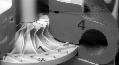
In a centrifugal compressor (Fig. 7.8), the flow enters axially, but is then turned radially out from the impeller. The flow turning is the reason why it is also called the radial compressor. The static pressure rises due to the decrease in the relative velocity, but also due to the centrifugal forces. After the impeller the flow enters a radially annular diffuser in which there can be blades. Because the radius increases, the diffuser can also be made without blades (parallel diffuser), where the flow is slowed down by the free vortex flow. The high complexity of the flow, especially in the rotating impeller, makes CFD modelling challenging. The radial compressor needs a gathering body (volute) to assemble the flow to the next stage or to the outlet piping. Usually the volute is a logarithmically increasing passage that ends in a circular outlet which is easy to connect to the piping. The velocities in the volute should be kept low to keep the pressure losses small.
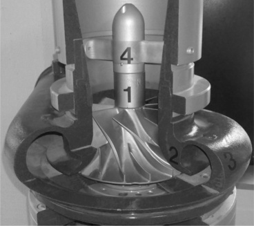
7.8 Main parts of the centrifugal compressor. 1 impeller, 2 vaneless diffuser, 3 volute and 4 inlet guide vanes. Photo LUT Energy.
As noted in previous chapters, the size of the microturbine is small and the best application is a recuperated cycle, where the pressure ratio is between 3 and 4. This pressure requirement is best suitable for a centrifugal compressor which can be made with a single stage unit. The axial compressor would need several stages even with lower pressure ratios and there have not been approaches to manufacture so small axial compressors.
If the electric power of a gas turbine is 100 kW, the power of the compressor is close to the same magnitude. The isentropic efficiency of a centrifugal compressor can be 85%, but the smaller the compressor the lower the efficiency. The efficiency of a 100 kW compressor is around 80% and with a 10 kW compressor it is closer to 70%. As the compressor consumes as much as the electricity power is, the compressor efficiency does have a strong influence on the overall performance.
The design principles of the compressors (and turbines) are based on fluid dynamics of the work done. The basic thermodynamic equations together with experimental data can quickly give rough results about the main geometry and the speed of the compressor. These methods have been used and enhanced by measuring the performance of the compressor.
The complex flow phenomena with the impeller of the compressor make the accurate design more laborious. Since the early 1990s the use of CFD and development of more accurate measurement methods have contributed to improving the efficiency of the centrifugal compressor. There are currently several commercial software packages available which allow the design of a well-performing compressor.
7.3.2 Turbines
Turbine design is critical in the microturbine cycle, because the power generated in the turbine determines the amount of electrical power produced by the machine. A turbine operating at high efficiency can be the factor that makes the cycle economically viable. We consider here two main types of turbines: the axial turbine and radial inflow turbine. The choice of the turbine type depends on many factors, including manufacturing costs, flow paths of the cycle, rigidity of the shaft, leakage questions and foreign particles in the flow. The axial turbine is commonly used in the commercial applications of medium or large size turbomachines, but in small machines radial inflow turbines are more often used.
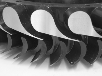
Radial turbines (Fig. 7.9), are widely used with small size turbochargers as they can be mounted back to back with the impeller of the centrifugal compressor. The turbine operates in a similar way as the compressor, but the flow direction is reversed. The combustion gases enter through the volute, the flow is accelerated in the nozzle vanes and the high velocity flow rotates the rotor wheel. In this impeller, the flow coming from the radial direction is turned and the flow exits in the axial direction.
The axial turbine stage has two blade cascades. The nozzle cascade is stationary and is used to increase the velocity of the flow (Fig. 7.10). The rotor cascade in turn reverts the flow velocity to work. The flow in the axial turbine is less complex than in the radial turbine, and therefore one can achieve higher efficiencies. Also foreign particles travel through the axial turbine without great problems. In the radial inflow turbine this can be a source of serious erosion, because the flow direction is inwards. There can be a situation where the flow forces thrust the foreign particles to swirl into the rotor impeller passage. The problem arises from the fact that the centrifugal force pushes the particles back out from the impeller. If the particles are stuck to circulate back and forth between the impeller and stator, there will very rapidly be serious erosion, especially in the rotating impeller blades (Wilson, 1991).
7.3.3 Heat exchangers for internal heat recovery
Heat exchangers are an essential part of microturbines irrespective of the cycle design. Commonly, heat exchangers are used to transfer heat from the turbine discharge flow into the power generation cycle, and in CHP operation to recover heat after the power cycle for external heating purposes. Some emerging configurations use intercoolers for cooling air between the compressor stages. We focus on the heat exchangers for internal heat recovery, recuperators and regenerators.
A recuperator is a gas-to-gas heat exchanger where a significant amount of heat of the hot exhaust gas (typically around 650 °c) is transferred to the compressed air (150-200 °c) before it enters the combustor (Soares, 2007). The most important performance parameter of the recuperator is the effectiveness that proportions the actual amount of transferred heat to the theoretically maximum amount. While the use of a recuperator is a prerequisite for achieving competitive electric efficiencies, it is also a subject for techno-economic optimization: an increase in effectiveness improves the efficiency strongly, but also increases the required heat transfer surface (investment costs) and pressure losses for a given design. Because of the gas-to-gas heat transfer, the recuperator is inherently characterized by low overall heat transfer coefficient, and hence large heat transfer surface. As a consequence, it is usually the most expensive single component of the microturbine.
The design and manufacture of the recuperators is a challenging task as they operate under high pressure and temperature differentials. Also, the connections (interfaces) of the recuperator must be carefully designed to avoid unnecessary pressure losses. The design criteria for maximum heat transfer surface and minimum pressure loss in the channels direct the heat exchanger design in favour of plate heat exchangers, as the traditional tubular heat exchangers would be too massive and expensive.
Current compact plate heat exchangers apply primary surface design where the flow channels are composed of a stack of formed plates. Due to their form, the plates constitute the fin effect without the additional layer of sheet metal fins between the plates as is the case with plate-fin recuperators, hence the name primary surface. Instead of brazing, the plates are pressed together to reduce thermal stresses in the structure. The primary surface design is featured by a large heat transfer surface area with respect to the heat exchanger volume, which results in compact size. The effectiveness values are up to 90% and the hydraulic diameters of the flow channels are in the order of a few millimeters. Despite the very narrow passages, fouling is typically not a problem because the combustion gases of gaseous and liquid fuels are practically particulate-free. Also, most microturbines apply oil-free bearings, which eliminate the risk of oil contamination on the hot side of the recuperator.
The recuperator design has two distinct shapes, an annular one surrounding the turbomachinery/combustor and a cubic one adjacent to the unit. The working temperature of the stainless steel recuperators is limited to 650 °C and superalloys increase the range to 800 °C. Ceramic materials allow temperatures in excess of 900 °C (Acunas et al., 2010), but their commercial use is still at an elementary stage.
Instead of a recuperator, a regenerator can be used where heat transfer takes place using a disk, usually of ceramic material, that rotates slowly (compared to the microturbine shaft) and is alternately exposed to hotter and colder flows. The exhaust heat warms first the section confronting the flow and as this part turns to the air channel, the heat is transferred to the pressurized air. The two flow channels are sealed from each other to minimize leakage flow from the high-pressure (air) to low-pressure (combustion gas) side. The leakage can be further reduced by using an intermittent operation where the heat transfer matrix is stationary and airtight most of the time, but experiences a periodical movement to maintain heat transfer. Compared to the recuperator, the regenerator can provide higher effectiveness, up to 98%, smaller pressure losses and with ceramic material higher operating temperature, but it requires separate rotation machinery to spin the disc (Wilson Solarpower, 2010). Although recuperators and regenerators are essential for high electric efficiency, they reduce the useful heat output from the microturbine.
7.3.4 Combustors
The role of the combustor is to provide a homogeneous combustion gas flow to the turbine with even temperature distribution (to avoid hot spots) and with small pressure loss. In a microturbine only part of the air flow is needed for the combustion process while the rest is mixed with the combustion gases to maintain the temperature of the gas mixture below limits set by the materials. Before mixing, the excess air is used to cool the combustor walls. Both single can type and annular combustors are used. While the former are typically used with separate recuperators, the latter allow for size reduction and adapt well in the integrated design with annular recuperators.
The microturbines that run on gaseous fuels apply lean premixed (dry low NOx) combustion where part of the combustion air is mixed with the fuel before the combustion zone and the rest is introduced into the combustion process in stages. Compared to the conventional diffusion type combustion with fuel and air separately injected into the flame zone, this arrangement reduces local temperature peaks in the flame, thereby lowering the formation of thermal nitrous oxides (NOx), the dominating NOx formation mechanism with microturbines. However, an advanced combustor design is necessary to ensure flame stability.
The combustion process in the microturbine is continuous unlike with reciprocating engines, for instance. This is favourable for the control of combustion and also for the completeness of combustion reactions. The combustion temperatures are also moderate compared to the reciprocating engines or larger gas turbines. Together with lean premixed combustion technology, these factors contribute to the very low emissions of NOx, carbon monoxide (CO) and unburnt hydrocarbons (UHC) in the current microturbines.
7.3.5 Bearings
There are stringent requirements for bearings to operate reliably for long periods with high rotational speeds.
Oil-lubricated bearings are widely used in turbochargers and are highly reliable, but they need a separate system for oil pumping, filtering and cooling. It is also difficult to prevent oil from penetrating into the exhaust gas, which causes fouling in the recuperator and limits the applicability of the exhaust gas in CHP operation. In microturbines this system will increase the investment and maintenance costs.
Gas bearings allow the shaft to rotate on a thin layer of ambient air where friction is low and no external delivery system is needed (Larjola, 1988). Gas bearings offer oil-free operation with practically no need for service. The main disadvantage is the metal contact of the shaft and bearing during start-ups and shutdowns, which may with an intermittent operation cycle require overhaul sooner than expected. During the last ten years especially, gas foil bearings have gained significant records with considerable amount of operating hours (capstone, 2010a).
Also active magnetic bearings (AMB) have been developed with the advances in power electronics to be a serious alternative with high speed machinery. Originally developed in the 1980s (SMM, 1984), the bearings offer contact free operation for the shaft. The bearings have two actuators for each of the two radial bearings and one actuator for the axial bearing. The magnetic forces are induced with DC current and the system uses electrical sensors to measure the position of the shaft.
7.3.6 Variable frequency drive
The microturbine electric generator produces a high frequency AC current of the respective rotational speed. If the speed is 90 000 rpm (1500 rps), the frequency is 1500 Hz which is 25-30 times higher than the normal electric net frequency. This high frequency current is rectified to DC current and then converted to 50 or 60 Hz AC current. The use of power electronics is necessary, but it also brings benefits to the microturbines. The units can be operated at the best possible speed if the load changes. Moreover, as the frequency conversion is performed electronically, the turbomachinery design is not affected by the grid frequency. The industrial gas turbines operate at constant speed, and therefore they differ considerably from each other depending on the frequency of the grid.
7.4 Operation
This section focuses on the recuperated microturbine of single-shaft configuration due to its prevailing role in the market.
7.4.1 Determination of the operating point
The operating point of the single-shaft microturbine is determined by the interaction between the compressor and turbine. The role of the compressor is to provide a pressure increase which subsequently causes the flow in the turbine. In practice, the pressure ratio and flow depend on the ambient conditions, rotational speed and turbine inlet temperature of the unit.
The properties of the compressor and turbine can be described using four parameters: pressure ratio π, mass flow qm, rotational speed N, and efficiency η (isentropic or polytropic). The interdependencies between the parameters are usually presented using characteristics (performance maps) that are specific to each turbomachinery type and design. The presentation of the characteristics varies, and Fig. 7.11 depicts one commonly used form. In the figure the subscripts 1 and 2 refer to the compressor inlet and outlet, respectively. Similarly, 3 and 4 refer to the turbine inlet and outlet. The parameters apply total state values where the speed of the working media is also taken into account and this is indicated by the subscript 0. The parameters for mass flow and speed have correction terms for the inlet pressure and temperature so the maps are applicable also for other inlet conditions than the reference case (Saravanamuttoo et al., 2008).
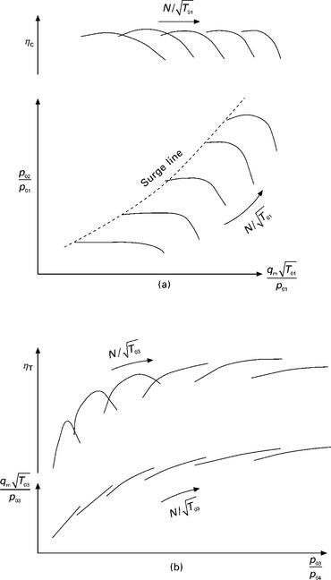
7.11 Example of (a) compressor and (b) turbine characteristics. Adapted from BorgWarner (2010).
Due to its role of increasing pressure, the compressor is susceptible to flow surge if the pressure increase becomes too high for the given speed. The limiting line is presented in Fig. 7.11 as the surge line. Surging is an unstable process with cyclic flow separation, delivery pressure collapse, flow reversal and reattachment. In addition to collapsing the mass flow and pressure delivery, surging strains or even damages the structure, and must therefore be avoided. To ensure stable operation, a safety margin is applied against surging conditions.
At high enough mass flow rate the constant speed parameter lines start to descend steeply. This indicates approaching the choking of the flow. At choked conditions the flow reaches the sonic velocity in the compressor and thereby the maximum flow rate for a given speed. Choking is not harmful for the compressor, but the pressure delivery and efficiency of operation decrease strongly.
For the turbine, a wider range for pressure ratio and mass flow is available than plotted in the figure for a given speed. However, the limited presentation is convenient for microturbine use where the compressor and turbine are interconnected. In this case the pressure ratio and mass flow rate typically both increase with increasing speed.
For a single-shaft configuration, the turbine mass flow data can be presented on the compressor map, and the operating point is determined by the intersection of the compressor and turbine curves. This enables the effect of ambient conditions and control methods on the transition of the operating point and, for instance, the surge risk to be studied graphically. Figure 7.12 is a schematic presentation of the resulting constant parameter curves, showing the principal directions for the operating point as a result of reducing single parameters of T01, T03 and N. The figure shows that a decrease in ambient temperature moves the operating point closer to the surge area, while decreasing turbine inlet temperature has an adverse effect. Changes in rotational speed move the operating point somewhat parallel to the surge line. The efficiency of the compressor is typically maintained best in the direction of the speed change.

7.4.2 Effect of ambient conditions
An open microturbine takes in surrounding air and therefore any changes in ambient conditions (temperature, pressure, humidity) affect the performance of the unit. Temperature, in particular, has a pronounced effect. An increase in ambient temperature decreases the mass flow through the microturbine, which has a negative effect on the net output. At the same time compressor discharge temperature is increased, thus impairing the prerequisites for the recuperator. As a result, generating efficiency is also decreased. A decrease in ambient temperature results in increasing output and efficiency. Depending on the capacity of the components (power electronics, for instance), power output may be limited below a certain temperature. Figure 7.13 presents the typical effect that ambient temperature has on the microturbine performance in this case. The power output and efficiency are given relative to the corresponding design values.

7.13 Effect of ambient temperature on power output and electric efficiency at nominal load (relative values). Adapted from Capstone (2010a).
Ambient pressure, or altitude, also has an effect on the performance, but compared to temperature, it is of minor importance for most applications. As an example, an increase of 1000 m in altitude (decrease of 115 mbar in pressure) decreases the power output by 11% (EEA, 2008).
7.4.3 Control methods
When the microturbine is connected parallel to the electricity grid, the control system typically aims at following the heat load. The reason for this is that the heat demand must be satisfied locally while electricity deficit/surplus can be balanced out using the network. In grid-independent operation electric load must be followed to prevent any imbalance. Surplus heat can easily be discharged to the atmosphere in the form of exhaust gases, but possible deficit must be covered by a supplementary system, such as a parallel boiler. Thermal storage is frequently used to compensate the diversity of supply and demand for both operational modes.
The output level (electric or heat) of the microturbine is reduced by lowering the rotational speed of the shaft. At the same time turbine inlet temperature is reduced to prevent temperature increase of the combustion gases at the recuperator inlet. As can be seen in Fig. 7.12, this affects the operating point of the microturbine, and consequently the mass flow rates, pressure levels and component efficiencies. The main contributing factor for output reduction is the decreased mass flow rather than heat supply temperature, and therefore this control mode maintains power generation efficiency at part load better than the conventional method with turbine inlet temperature as the only control parameter. However, efficiency reduction cannot be avoided using this control mode either. Figure 7.14 presents the typical behaviour of electric efficiency at part load, with the performance parameters given relative to the corresponding design values. The strong decrease in electric efficiency contributes to the heat output, but in practice heat transfer rate decreases. This is due mainly to the decreased exhaust mass flow rate. As a result, the system experiences a slight reduction in total efficiency, too.
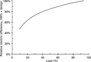
7.14 Effect of electric load on electric efficiency (relative values). Adapted from EEA (2008).
7.4.4 Emissions
The main pollutants from the microturbines are NOx, CO and UHC. While NOx is the result of thermal NOx formation, CO and UHC are indicative of incomplete combustion.
Microturbines that operate on gaseous fuels apply lean premixed combustion which is one of the key factors for low NOx emissions. At full load and using natural gas as fuel, the guaranteed emission levels (at 15% O2) are below 15 ppmv and in some cases even below 9 ppmv, with the lowest figure of 4 ppmv. The UHC emissions are of the same magnitude but CO emissions are somewhat higher, up to 40 ppmv (EEA, 2008; Capstone, 2010a; Turbec, 2010). This is attributable to the use of lean premixed technology that has a tendency to increase CO emissions. At part load all emissions typically increase.
The noise in microturbines is generated primarily internally by flow vortices, blading, magnetic fields and combustion (Kolanowski, 2004). The current microturbine technology with a recuperator and contactless bearings effectively attenuate the transmission of noise through exhaust gases and microturbine casing. As a result, the noise levels are reasonably low, at full load the acoustic emission at 10 m distance is typically 65-70 dBA. An additional sound insulation in the inlet channel can be used to further decrease noise (Capstone, 2010a; Turbec, 2010).
7.4.5 Other operational viewpoints
Microturbines operate best with premium fuels such as natural gas, liquefied petroleum gas (LPG), diesel and kerosene. In case of low-grade fuel gases such as biogas or industrial waste gases, the fuel often contains acid gas components, oils or particulates that may require fuel pre-treatment (EEA, 2008).
The high-speed generator of the microturbine can be used as a motor, which makes the start-up of a single shaft microturbine very straightforward: the motor starts to rotate the shaft and increases the speed until compressor delivery reaches the conditions for self-sustaining combustion. Fuel is introduced in the airflow and the mixture is ignited. After this fuel power is increased together with the speed of the shaft (now controlled by the generator) until nominal output is achieved. In grid-independent operation, a battery is used as power storage for start-up.
Microturbines have relatively short start-up and shutdown times, with full power or complete stop in a couple of minutes after initiating the sequence. At start-up, power delivery begins in around 30 s (Kolanowski, 2004).
One significant feature of the variable frequency drive is that during short periods of no-load, the speed can be lowered to the idle level where combustion still occurs but no net electricity is generated. From this operation mode power can be increased very quickly. Avoiding bringing the shaft to a halt also increases the life of the bearings, as the stopping and starting pose the most wearing conditions for both gas and magnetic bearings.
Microturbines can be operated in a variety of ways. They can run in parallel with the electric grid or as a stand-alone system, following the electric or heat load. Single units can be interconnected to increase capacity or reliability. The engines are equipped with control and protection systems that allow remote operation and interconnection as well as monitoring/diagnostics of the units.
The single-shaft microturbines feature essentially only one rotating part. Together with gas or magnetic bearing technology, this provides the possibility for low maintenance needs together with high reliability and life of the units. A typical preventive maintenance schedule includes periodic inspection and minor replacements with the major overhaul due every 30 000 to 40 000 turbine run hours. In the overhaul the shaft with the attached components, and possibly the combustor are replaced (Capstone, 2010a; Turbec, 2010). The life estimates for the main parts vary between 40 000 and 80 000 hours, but due to the late emergence of the microturbines, these estimates are currently being tested in real operating conditions.
7.5 Manufacturers and applications
The market for microturbines is still in the developmental stage. The largest manufacturer, Capstone Inc., has sold 5000 units (Capstone, 2010b). Although the figures also include units above 100 kW, the total power is less than 500 MW, which is equivalent to one to two large industrial gas turbines.
There have also been some changes among the manufacturers. Calnetix Power Solutions (a company based in California, USA) acquired in 2007 Elliott Energy Systems (a subsidiary company of Ebara Corporation of Tokyo, Japan) that was manufacturing 100 kW microturbines and in 2010 Capstone (California, USA) acquired the TA 100 microturbine production line from Calnetix.
7.5.1 Capstone
Capstone Turbine Corporation is one of the world’s leading manufacturers of microturbines, and was first on the market with commercially viable air bearing turbine technology. The company has shipped thousands of microturbines to customers worldwide and the systems have logged millions of documented runtime operating hours. Capstone makes various sizes of microturbines: 30, 65 and 200 kW. Products based on the three turbine models are also available in configurations between 100 and 1000 kW. Capstone is predicted to sell annually around 700 units below 100 kW in the coming years (Soares, 2008).
The Capstone microturbine comprises a single-stage centrifugal compressor, a radial inflow turbine and a recuperator (Fig. 7.15). It can be operated on natural gas, biogas, flare gas, diesel, propane and kerosene. The microturbines can be used for producing electric power only or as a CHP unit or also providing cooling (Capstone, 2010a).
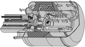
7.15 Capstone microturbine. Air enters the compressor around the generator and exits into the recuperator on the outer periphery. Warmed air is led to the combustor, combustion gases rotate the turbine and exhaust gases exit through the secondary side of the recuperator (NASA, 2003).
7.5.2 Turbec
Turbec has its roots in the development of small gas turbines for automotive use in the early 1970s, where a permanent magnet high-speed generator was designed (Malmquist, 1988). Turbec was founded in 1998 and has its head office in Italy. The first commercial T100 unit was delivered in 2000. The microturbine comprises a single-stage centrifugal compressor, a radial inflow turbine and a recuperator. The compressor pressure ratio is 4.5 (Turbec, 2010). The microturbine uses a combustor that can run on various fuels such as natural gas, diesel, ethanol and biogas. The electrical efficiency using natural gas is 33% with a 1 percentage point uncertainty. The shipped units of Turbec microturbines have more than 3 million operating hours (Turbec, 2010). Annual sales are predicted to be around 100 units (Soares, 2008).
7.6 Future trends
7.6.1 Externally-fired microturbines
Biofuels are especially suitable for distributed energy systems, as their transportation is often economically feasible only over short distances. Microturbines can easily utilize biogas but interest is currently focusing on direct biomass combustion too, due to simple and widespread combustion technology.
Taking the combustion gases directly to the turbine poses a challenge for operation and maintenance because of the fouling nature of the combustion products. Therefore, there have been many suggestions to use externally-fired microturbines (EFMT) where the heat is transferred to the power cycle by using a heat exchanger (Fig. 7.16). The heat exchanger inevitably increases the investment costs and sets limitations on the heat supply temperature, but the benefit is that the outlet flow from the microturbine is hot air. When using gas or magnetic bearings and thus having no risk of oil-contamination, this air can be used directly for space heating, for instance.
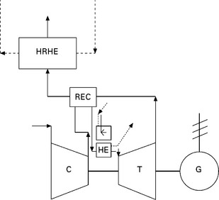
7.16 Flow diagram of an externally-fired microturbine cycle. C compressor, T turbine, G generator, REC recuperator, HE heat exchanger and HRHE heat recovery heat exchanger.
One of the first examples is Talbott’s Heating (Pritchard, 2002, 2005) who has developed and field-tested a 100 kW EFMT unit with 17% electric efficiency. Another demonstration is by Compower (Malmquist, 2006) who has focused on smaller, under 15 kW scale. Currently most major microturbine manufacturers have expressed their interest in and target to introduce externally-fired microturbine versions into the market.
7.6.2 Fuel cells and microturbines
Studies with fuel cell technology combined with a gas turbine cycle are promising very high electric efficiencies compared to conventional gas turbine cycles (Backman et al., 2004). The development of the fuel cell technology has been slower than expected and the integration of gas turbines is still at an elementary stage.
With the solid oxide fuel cell (SOFC), the exhaust gas temperature is as high as 800 °C, which is suitable for a recuperated gas turbine cycle. The recent approaches include a dynamic performance analysis to use the Turbec T100 recuperator with a fuel cell set-up (Ferrari et al., 2010). The fuel cell may either be operated at ambient pressure or pressurized, which determines the method of integration. In many designs the fuel cell is pressurized with a pressure of around 3 bars, which suits well the recuperated gas turbine cycle (Figs 7.1(b) and Fig. 7.17).
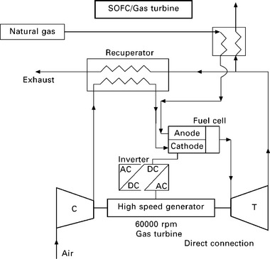
7.17 Gas turbine integrated to a fuel cell (Backman et al., 2004).
If the fuel cell operates at ambient pressure, the gas turbine can be integrated using the external heat source as shown in Fig. 7.16, where the hot exhaust gases from the fuel cell are heating the compressed air entering the turbine. This additional heat exchanger lowers the electric efficiency compared to the pressurized operation, but the air entering the turbine is clean and there are no significant erosion problems.
7.6.3 Pushing the envelope
There are projects within various research institutes to design and construct small microturbines. Provided they could be operated with a reasonable efficiency and sold at an affordable price, there could be a breakthrough for household microturbines.
Micro Turbine Technology MTT b.v. in the Netherlands is developing a recuperated microturbine CHP concept that will provide 3 kW electrical and 15 kW thermal power for consumer as well as small and medium enterprise markets (MTT, 2010). It has been demonstrated to give 2.7 kW electricity at 12.2% electrical efficiency (Visser et al, 2010). Further development is currently focused on at least 16% efficiency and the researchers believe that the technology could reach efficiencies beyond 20%.
Researchers at the Research Center of Ceramic Engines in Saint Petersburg have developed a new turbo machinery, the tunnel turbine made of ceramics. Their design at the smallest size is 200 W (Soudarev et al., 2008).
MIT has conducted research on micro-electrical-mechanical systems (MEMS) based microturbines (Epstein, 2003). Due to the small size, the efficiency is around 6%.
7.7 Sources of further information and advice
Compressor and turbine design software is now widely available as commercial products, but their use does require good knowledge of fluid mechanics and turbomachinery. Below are listed examples of well-known software providers.
Advanced Design Technology: http://www.adtechnology.co.uk/products/
ANSYS CFX: http://www.ansys.com/products/fluid-dynamics/cfx/
CFTurbo: http://www.cfturbo.de/en/
Concepts NREC: http://www.conceptsnrec.com/
ANSYS FLUENT: http://www.fluent.com/
PCA Engineers Limited: http://www.pcaeng.co.uk/
SoftlnWay: http://www.softinway.com/
7.8 References
Acuñas, A., Huete, J., Amallobieta, I. Recent Advances in High Temperature Ceramic Regenerators for Externally Fired Gas Turbines. Theoretical and Experimental Results. ASME Paper GT2010-23806, ASME Turbo Expo 2010. Glasgow, United Kingdom, 2010.
ATT, Agile Turbine Technology. Publications. Available from http://www.agileturbine.com/publications/index.html, 2010.
Backman, J., Reunanen, A., Esa, H., Punnonen, P., Honkatukia, J., Larjola, J., Concept Design of a Solid Oxide Fuel Cell Gas Turbine 11-13 Oct 2004. 3rd International Conference on Heat Powered Cycles, Larnaca, Cyprus. 2004.
Balje, O.E. Turbomachines, A Guide to Design, Selection and Theory. New York: John Wiley & Sons; 1981.
Baskharone, E. Principles of Turbomachinery in Air-Breathing Engines. Cambridge: Cambridge University Press; 2006.
BorgWarner. Turbo-Facts. Available from http://www.turbodriven.com/en/turbofacts/designAndFunction.aspx, 2010.
Boyce, M.P. Gas Turbine Engineering Handbook, 3rd edition. Oxford: Gulf Professional Publishing; 2006.
Capstone. Products. Available from http://www.capstoneturbine.com/prodsol/products/, 2010.
Capstone. News. Available from http://www.capstoneturbine.com/news/story.asp?id=573, 2010.
Casey, M. The effect of Reynolds number on the efficiency of centrifugal compressor stages. Journal of Engineering for Gas Turbines and Power. 1985; 107:541–548.
Dong, L., Liu, H., Riffat, S. Development of small-scale and micro-scale biomass-fuelled CHP systems-a literature review. Applied Thermal Engineering. 2009; 29:2119–2126.
EEA, Energy and Environmental Analysis. Technology Characterization: Microturbines. Available from http://www.epa.gov/chp/documents/catalog_chptech_microturbines.pdf, 2008.
Epstein, A. Millimeter-Scale, MEMS Gas Turbine Engines, ASME Paper GT2003–38866, ASME Turbo Expo 2003. USA: Atlanta; 2003.
Ferrari, M., Sorce, A., Pascenti, M., Massardo, A. Experimental Investigation of the Dynamic Performance of a Micro Gas Turbine Recuperator including Innovative Cycle Configurations, ASME Paper GT2010-22299, ASME Turbo Expo 2010. United Kingdom: Glasgow; 2010.
Galanti, L., Massardo, A. Thermoeconomic Analysis of Micro Gas Turbine Design in the Range 25-500 kWe, ASME Paper GT2010-22351, ASME Turbo Expo 2010. United Kingdom: Glasgow; 2010.
Kolanowski, B.F. Guide to microturbines. Lilburn, GA: Fairmont Press; 2004.
Larjola, J., Basic properties of gas lubricated, tilting-pad journal bearing, Conference on High Speed Technology, 21-28 August, Lappeenranta, Finland. 1988.
Malmquist, A. 21-28 August. Conference on High Speed Technology. Lappeenranta, Finland, 1988.
Malmquist, A., Swedish Micro-CHP Solution - ‘Externally Fired Microturbine System’. 2nd World Pellets Conference, Jönköping, Sweden. 2006. [30 May-1 June].
Moran, M.J., Shapiro, H.N. Fundamentals of Engineering Thermodynamics, 6th edition. Hoboken, NJ: Wiley; 2010.
MTT, Micro Turbine Technology. Available from http://www.mtt-eu.com/, 2010.
NASA. Research & Technology reports. Available from http://www.grc.nasa.gov/WWW/RT/RT2002/5000/5960weaver.html, 2003.
Pritchard, D. Biomass Combustion Gas Turbine CHP, ETSU B/U1/00679/00/REP. Available from http://webarchive.nationalarchives.gov.uk/+/http://www.berr.gov.uk/files/file14922.pdf, 2002.
Pritchard, D. Biomass Fuelled Indirect Fired Micro Turbine, B/T1/00790/00/00/REP, DTI/Pub URN 05/698. Available from http://webarchive.nationalarchives.gov.uk/tna/+/http://www.dti.gov.uk/renewables/publications/pdfs/bt100790.pdf/, 2005.
Saravanamuttoo, H.I.H., Rogers, G.F.C., Cohen, H., Straznicky, P.V. Gas Turbine Theory, 6th edition. Upper Saddle River, NJ: Pearson Prentice Hall; 2008.
Siemens. Siemens Gas Turbines. Available from http://www.energy.siemens.com/us/en/power-generation/gas-turbines/, 2010.
SMM, Société de Mécanique Magnétique. Application of Active Magnetic Bearings in the Machine Tool Industry. France: Vernon Cedex; 1984.
Soares, C. Microturbines: Applications for Distributed Energy Systems. Elsevier Butterworth-Heinemann; 2007.
Soares, C. Gas Turbines: A Handbook of Air, Land, and Sea Applications. Maryland Heights, MO: Elsevier Butterworth-Heinemann; 2008.
Soudarev, A., Konakov, V., Morozov, N., Ovidko, I., Semenov, B., Novel Shrinkage- Free Structural Ceramic Materials for Gas Turbine Applications, ASME Paper GT2008-50549, ASME Turbo Expo 2008, Germany, Berlin. 2008.
Turbec. Products. Available from http://www.turbec.com/products/products.htm, 2010.
Visser, W., Shakariyants, S., Oostween, M. Development of a 3 kW Micro Turbine for CHP Applications, ASME Paper GT2010-22007, ASME Turbo Expo 2010. United Kingdom: Glasgow; 2010.
Wilson, D.G. The Design of Gas Turbine Engines, Thermodynamics and Aerodynamics. Atlanta, GA: IGTI/ASME; 1991.
Solarpower, Wilson. Wilson Heat Exchanger. Available from http://www.wilsonturbopower.com/index.php/nonsolarapps/heatexchanger.html, 2010.