
Fuel cell systems for small and micro combined heat and power (CHP) applications
Abstract:
Fuel cells are electrochemical energy conversion devices that turn chemical fuel directly into electrical power as well as generating heat. They operate at high efficiency and can be applied across a wide range of applications. Micro-combined heat and power (CHP) is one area in which fuel cells are expected to have a particularly significant impact with the potential for lowering energy cost and CO2 emissions in the residential housing sector. This chapter looks at the technological aspects of fuel cells applied to micro- and small-scale CHP applications as well as examining the state of commercial development and future trends.
10.1 Introduction
Fuel cells are electrochemical devices that convert the chemical energy of a fuel directly into electricity and heat without involving the process of combustion. A simplistic view of a fuel cell is a cross between a battery (chemical to electrical generator) and a heat engine (chemical to heat to generator) (Hawkes et al, 2009a). There are a number of fuel cell technologies with very different designs, each suited to different applications; however, they all share the characteristics of high efficiency, no moving parts, quiet operation, and low or zero emissions at the point of use. In addition, modular stack design means that there are no technical limitations on minimum capacity, which is a problem for mechanical heat engines. The range of fuel cell applications and size of the potential markets are enormous, including: battery replacement in small portable electronic devices, prime movers and/or auxiliary power units in vehicles, large scale (megawatt) electrical power generation and high-reliability backup power. Fuel cells are also well suited to providing combined heat and power (CHP) at both the 'micro' scale, relevant to domestic and small commercial loads (ca. 1-5 kWe) and 'small' scale, suitable for larger commercial and municipal applications (tens of kWe). It is the small- and micro-scale CHP application for fuel cells that is the subject of this chapter.
10.2 Fundamentals of operation, types and properties of fuel cells
10.2.1 Fundamentals of operation
Individual fuel cells consist of an anode, electrolyte and cathode, and are electrically connected in series to form a 'stack'. Electrically conductive interconnectors (or bipolar plates) are used to distribute fuel and oxidant to the individual cells, and to electrically connect them together. Coolant fluid can also be distributed through channels in the interconnects, or through additional plates inserted between cells.
Taking the low temperature polymer electrolyte fuel cell (PEFC) operating on hydrogen as an example, Fig. 10.1 shows the basic operation. Electrons are stripped from the incoming hydrogen at the cell anode, forming ions which pass through a conductive electrolyte to combine with oxygen at the cathode. The stripped electrons produce an electric current through the external circuit and do useful work. The exact reactions that occur depend on the type of fuel cell (as several technologies exist), but for hydrogen fuelled cells, the overall reaction is the same as that of fuel combustion: H2 + ½O2 → H2O.
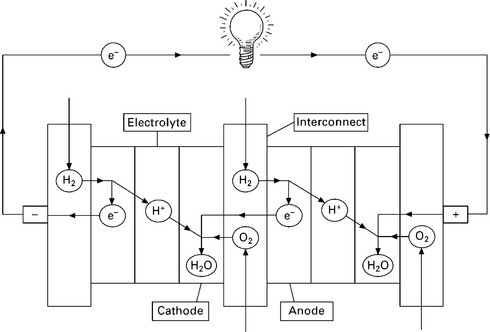
10.1 illustration of fuel cell operation (two cells in a stack) taking the hydrogen fuelled polymer electrolyte fuel cell (PEFC) as an example.
Figure 10.2 (a) illustrates the voltage and power dependence on current output for a generic fuel cell. An increase in current density (current per unit area of each cell) results in a decrease in operating voltage due to internal losses in the system. Power output initially increases with current and reaches a maximum at point D, above which the decreasing voltage and increasing losses in the system result in loss of electrical power output, although the heat generated continues to increase. The nominal operating point is around point C, typically ~ ⅔ to ¾ of the open circuit voltage (OCV) of the cell (which is around 1 V for a PEFC operating on hydrogen). The point of operation is a trade-off between electrical efficiency and capital cost (Ang et al., 2010), and for a CHP system the requirement to service the heat load is also a factor in determining the operating point.
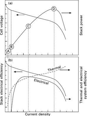
10.2 illustration of the operating range of a fuel cell, showing (a) stack voltage and power and (b) electrical and thermal efficiency. Labelled operation points are described in the text.
Considering the whole fuel cell system, Fig. 10.2(b) shows how the electrical and thermal efficiency varies with electrical load. In contrast to heat engines, which have a maximum efficiency at their nominal operating point, fuel cells are known to have excellent 'turn-down' performance, i.e. reducing the electrical load results in higher electrical efficiency, to a point. However, since there are components that require electrical supply (e.g. sensors, actuators, control system), and their load is constant regardless of the power delivered by the fuel cell, this parasitic load degrades the system efficiency at low electrical load. There is a point B where the parasitic load equals the power delivered by the fuel cell and the system therefore has ' zero efficiency'. In a similar sense, high temperature fuel cell stacks such as solid oxide fuel cells (SOFCs) need to generate heat to maintain their operating temperature, and so have a lower bound on their operational window below which the stack is no longer thermally self-sustaining and begins to cool. There is therefore a practical lower limit below which the system cannot operate. The exact point will depend on the size, shape and materials used to construct the SOFC, but is typically of the order of 20% of the nominal operating point.
It can be seen from Fig. 10.2(b) that as the electrical load on the fuel cell increases, the thermal efficiency increases and the electrical efficiency decreases. The way in which the heat-to-power ratio (HPR) of the fuel cell varies with electrical load will depend very much on the system design, but will generally tend to increase when subjected to heavy electrical loading. However, it should be remembered that the heat-to-power ratio of the system can also be controlled at any fuel cell operating point by varying the fuel utilisation and the amount of heat generated in the afterburner.
Hydrogen is the ideal fuel for most fuel cell types based on performance and durability; however, it is not practical for direct use in homes since no hydrogen generation or distribution infrastructure currently exists. Instead, hydrocarbons (particularly natural gas) are seen as the ideal fuel for micro-CHP systems, as these can be reformed into hydrogen at the point of use (Hawkes et al., 2009a). Natural gas is low cost, abundant (for the time being), and has extensive infrastructure throughout Western Europe. All commercial fuel cell micro-CHP systems are fuelled by natural gas, LPG or kerosene. However, academic studies have also described systems running off gasified coal (Marquez et al., 2007), diesel (Lindström et al., 2009), biogas from waste (Kiros et al., 1999; Spiegel et al., 1999), biomass (Xuan et al., 2009), and biologically produced hydrogen from sugary waste (Penfold, 2004; Redwood, 2008).
One of the criticisms of fossil fuelled micro-CHP is that it may be limited to a 20-30-year window of opportunity, after which the scarcity of natural gas and decarbonisation of centralised electricity would make it unattractive (Harrison, 2008). The potential to operate fuel cells on various types of biogas would, however, offer a solution to this problem, whilst giving profound reductions in CO2 emissions, assuming a sustainable and carbon-neutral production route could be found (Redwood, 2008; Das and Veziroglu, 2001; Wakayama and Miyake, 2001).
10.2.2 Types of fuel cell stack
There are more than a dozen distinct fuel cell technologies under academic and commercial development; however, only few are suitable for domestic small- and micro-CHP. For this application the fuel cell stack must have (at least the potential for) low cost manufacture and long operating lifetime in sub-optimal conditions, particularly with regard to impurities in the hydrogen fuel. There are also considerations about safety, practicality and cost-effectiveness to consider, which favour those technologies that are well established and commercially demonstrated, and offer high operating efficiency. Four fuel cell technologies have been applied to CHP applications:
• PEFC: polymer electrolyte fuel cells;1
• SOFC: solid oxide fuel cells;
While these technologies share the same operating principles outlined in the previous section, there are some fundamental differences in the way they achieve their electrochemical reactions. Three of the characteristic differences are the diverse materials they are made from, their range of operating temperatures and the fuels they can tolerate. Table 10.1 summarises the typical materials of construction of each fuel cell type, along with their operating conditions and tolerances to fuel impurities.
Table 10.1
General operating characteristics of each fuel cell technology, taken from (Staffell, 2010)
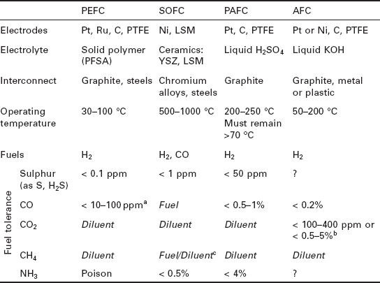
Abbreviations: PTFE (polytetrafluoroethylene - better known as Teflon™), PFSA (perfluorosulfonic acid - for example Nation™), YSZ (yttria-stabilised zirconia), LSM (lanthanum-strontium-managanate).
aStandard Pt anode catalysts can only withstand CO concentrations up to 10 ppm, and PtRu alloys up to 30 ppm (Song, 2002). These limits can be extended by bleeding air into the anode and using alternative bi-layer catalysts (Uribe et al., 2004; Ball and Thompsett, 2002).
bCO2 tolerance is highly dependent on the cell design. Strongly bonded nickel and silver electrodes with a circulating electrolyte can be tolerant, while platinum and carbon with an immobilised electrolyte are highly sensitive.
cInternal reforming is possible with SOFC anodes, making desulphurised natural gas a viable fuel. The long lifetimes required for domestic CHP operation have not yet been demonstrated by these systems though.
Domestic CHP systems based on PEFC and SOFC stacks have received intense research and commercial development over the last decade. There are at least a dozen major companies actively pursuing this market, and products have been deployed in large-scale field trials throughout Japan, South Korea and Germany. The majority of this chapter will therefore focus on these two technologies.
Despite being developed 10-20 years earlier, PAFCs and AFCs failed to retain substantial commercial interest due to difficulties in overcoming high manufacturing cost and low lifetime, respectively. No significant products have been developed for the domestic CHP market; however, they possess many of the desired characteristics and have been demonstrated at the 1-10 kWe scale operating on natural gas as CHP units (Ghouse et al., 2000; Independant Power Technologies Ltd, 2006).
10.2.3 Materials for PEFCs and SOFCs
PEFC technologies use precious metal electrocatalysts (e.g. platinum) to ensure adequate electrode reaction kinetics for a high power output. Specialised graphite powders and resins are used, along with the fluorinated polymer electrolytes found in modern chlorine electrolysis cells. High purity hydrogen fuel is required to avoid performance degradation, as the electrocatalysts are easily poisoned by carbon monoxide and other impurities. Management of fuel impurities and hydration of the polymer electrolyte requires relatively complex and expensive engineering solutions, and current work is aimed at relaxing these strict requirements by increasing the operating temperature to over 100 °C (Zhang et al., 2006).
SOFCs instead use ceramics and specialist chromium alloys or steels that can withstand high temperatures. For micro-CHP applications there is a trend to move from the high temperature region (850-1000 °C) used in early large-scale systems, into the so-called intermediate temperature (IT) range of 500-750 °C (Brett et al., 2008). This allows a wider range of materials to be used, giving cheaper fabrication and improved resilience to cycling ceramic components between ambient and operating temperatures. Lower temperature operation also affords more rapid start-up and shut-down, reduced corrosion rate of metallic components, more robust construction through the use of compressive seals and metallic interconnects as well as the advantage of greatly simplified system requirements (Brett et al., 2008).
10.3 Fuel cell systems
10.3.1 Fuel cell stack
Figure 10.3 shows a generic fuel cell system for CHP applications running on reformed hydrogen from natural gas. The major balance-of-plant (BoP) items are shown (i.e., the auxiliary components that enable the fuel cell to operate); however, there are many additional components required for operation such as pressure valves, mass flow controllers, sensors, control systems, etc. that are not included. The key issues for each of the main components of the system are now described.
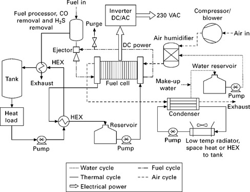
The combination of individual fuel cells into an interconnected 'stack' represents the main and most expensive component of the entire system. The stack is composed of individual cells (anode, electrolyte and cathode) electrically interconnected using bipolar plates that also distribute reactant to the electrodes. PEFC stacks are usually interspersed with cooling plates that circulate demineralised water, while SOFC stacks rely on air for cooling.
10.3.2 Fuel processor
Converting natural gas into an acceptably pure supply of hydrogen requires several processing stages, as outlined in Fig. 10.4. The required stages for each type of fuel cell stack are integrated into a single, compact fuel processing unit, along with the thermal management systems and a steam generator to supply water vapour to the reformer and shifter (Echigo et al., 2004; Yasuda et al., 2001).
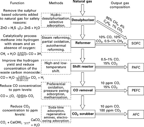
10.4 An overview of fuel processing for fuel cell systems. Each stage is highlighted in bold down the centre of the diagram and given with the most common processing methods. A description of each stage is given at the far left, along with the ideal reactions for the primary method. indicative ranges of gas composition after each stage are given to the right. Following the stages down from natural gas to each type of fuel cell on the right indicates which processing stages are required. Reproduced from Staffell (2010).
An SOFC fuel processor is typically composed of a desulphuriser and pre-reformer; whereas PEFCs require a larger reformer, and additional shift reactor and gas clean-up stage, all of which add to the cost and complexity, and erode the total system efficiency. The ability of SOFCs to operate at high efficiency on hydrocarbon fuels is a major advantage over low temperature fuel cells, particularly for micro-CHP applications.
Natural gas (or other hydrocarbon fuels) can be converted to hydrogen via a range of processes, including: steam reforming, partial oxidation and autothermal reforming (Kolb, 2008). Steam reforming is generally the preferred method as it produces higher concentrations of hydrogen, and thus requires up to 30% less hydrocarbon fuel (Hubert et al., 2006).
The hydrogen rich steam leaving the reformer will contain a proportion of CO and sulphurous compounds (usually converted to H2S in the reforming stage) from the fuel source and added odorants. Both of these molecules are poisonous to PEFCs, while SOFCs are able to use CO as a fuel but remain highly sensitive to many sulphur-containing molecules (Lohsoontorn et al., 2008a; 2008b). These must therefore be removed, usually by reacting with ZnO or adsorption using activated carbon. These units will need to be changed periodically, adding to the maintenance cost of the system. Cther desulphurisation techniques exist, but most are not suitable for such small-scale applications (Kolb, 2008).
For PEFCs, the level of CO entering the fuel cell needs to be reduced to the order of < 100 ppm in order not to poison the Pt-based anode electrocatalyst. The output from the reforming stage contains an appreciable quantity of CO (typically ~10%) (Brett et al., 2007). CO produced in the steam reforming process can be converted subsequently to CO2 in a shift reactor, reducing the CO concentration to the order of < 1%. Techniques such as selective oxidation of CO and oxygen bleed can be used to reduce the CO concentration to safe levels for the PEFC, at the expense of cost and efficiency, respectively.
The fuel processor for a PEFC is therefore a relatively complicated system, each stage requiring tight temperature control and thermal management. A high degree of thermal integration is required, as the optimal temperatures for each reaction range from ambient to several hundred degrees, and attaining high thermal efficiency is paramount to the overall efficiency of the fuel cell CHP system (Woods and Cuzens, 2001). While this is relatively straightforward for large systems operating at steady state, dynamic operation and the size of small- and micro-CHP fuel processors are much more of a challenge. In particular, the turn-down ratio (the minimum sustainable power output relative to the maximum) is compromised since it is difficult to maintain thermal homogeneity due to the relatively large surface-to-volume ratio of smaller units.
SOFC systems have a clear advantage over PEFCs here, since they are capable of fully internally reforming hydrocarbon fuels. Studies have, however, shown that a small pre-reformer can improve SCFC performance by damping the effects of the strongly endothermic reforming reaction that can lead to excessive thermal stresses in the SOFC stack and shorten the operating lifetime (Schmidt, 2006).
The most striking difference between fuel processors from major manufacturers is the choice of reforming method; the majority choose steam reforming, although Plug Power (USA) and Hexis (Switzerland) use the other methods listed in Fig. 10.4 (Hubert et al., 2006). The main benefit of steam reforming is the high concentration of hydrogen in the output reformate -70-80%, compared with 50-60% for autothermal and even less for partial oxidation; which consequently gives the highest operating efficiency (Woods and Cuzens, 2001). The drawbacks are that the highly endothermic reaction (-250 kJ mol- 1 CH4) and high operating temperature (up to 800 °C) prevent the rapid start-up and transient performance that can be achieved with other methods (Woods and Cuzens, 2001; Yasuda et al., 2001).
10.3.3 Reactant delivery systems
Since small- and micro-CHP systems are not pressurised, a blower rather than a compressor is used to supply air to the system. The air blower is the main parasitic electrical load on the system, the power requirement scaling with the mass flow rate of air delivered. The mains gas pressure that enters a home, and certainly the pressure of tanked storage, is usually sufficient to operate a small- or micro-CHP system.
The high temperature operation of SOFCs means that the fuel and air entering the stack need to be pre-heated to a level that avoids thermal shock to the ceramic components of the stack. Therefore, appropriately sized heat exchangers are required to heat the reactant streams and raise steam if a reformer is used.
Silent operation is often cited as a benefit of fuel cells. While it is true that the fuel cell stack operates silently, the blowers, pumps, water evaporation generators, burner, etc., required to operate it will generate a noise level similar to that of a conventional condensing boiler. However, compared to mechanical CHP engines, fuel cell systems should be noticeably quieter; ca. 40-55 dB for fuel cell systems compared with around 95-99 dB for CHP engine-based technologies (Garche and Jörissen, 2003).
10.3.4 Water management
High purity water is required for steam reforming and to maintain adequate hydration of the electrolyte membrane in PEFCs to ensure proton conduction. Heat exchanger condensers remove water from the exit of the stack, harvesting heat and supplying process water to these components. An ion-exchange pack is often used to ensure the purity of the water before feeding it back in the cell, since cation contamination can increase the rate of degradation of membrane electrolytes and certain anions affect the electrocatalysts.
10.3.5 Heat management
Heat recovery from fuel cell stacks is markedly different depending on the stack technology. High temperature SOFC stacks are cooled by excess air flow over the cathode, which is then combusted with unconsumed fuel in an afterburner. This heat is used to pre-warm the gas inlets to the stack and maintain reformer temperature, and the excess is passed through a condensing heat exchanger to provide hot water for the home (Hawkes et al., 2009a).
Low temperature stacks are cooled by circulating a liquid through cooling plates interspersed through the stack, which is then passed through a liquid-liquid heat exchanger. The low operating temperature of PEFC systems means that heat output is limited to 60-65 °C, and a boiler is needed to produce hot water at higher temperatures, if required (Osaka et al., 2005).
10.3.6 Heat storage
The hot water output is stored within a large, well insulated tank, which is gradually filled by the low capacity fuel cell throughout the day. These heat stores improve on conventional hot water cylinders by promoting thermal stratification with mixing valves and buffer zones. The majority of the water is stored as a warm buffer (~45 °C) that is used as an intermediate heat exchanger between the generator and the central heating system. A smaller tank sits in the centre of the store, holding around a quarter of the water at a higher temperature for direct consumption (Staffell et al., 2010).
The heat stores supplied with fuel cell micro-CHP systems range from 75 to 750 L, the upper end of which would traditionally be recommended for houses with five or more bathrooms (Staffell, 2010). The space required by such a tank poses a problem for installation in smaller houses, so they are currently installed in basements or outside. A 600 L tank would hold around 28 kWhth - just over half a day's requirement from a typical British house.
10.3.7 Auxiliary burner
In cool climates such as the UK, houses are notoriously poor at retaining their heat and there is generally lower demand for electricity as air conditioning is not widespread (Colella, 2002). The annual average HPR of UK houses is around 5.5:1, which is more than triple that of most fuel cell CHP systems (Utley and Shorrock, 2008; Hawkes et al., 2009a). It is unlikely that a significant portion of the UK housing stock will be retrofitted with the exceptional insulation needed for a tenfold reduction in space heating demand,2 so an additional heat source is required to prevent the fuel cell owner from experiencing a loss in comfort in winter. It would take the fuel cell alone several hours to replenish the typical sized hot water tank, so an auxiliary boiler is also required when the household demands a lot of hot water (Osaka et al., 2005).
A condensing boiler is therefore integrated into commercial micro-CHP systems. Japanese PEFC and SOFC systems are typically backed up by a 42 kWth gas burner, while the leading European PEFC systems contain a 15 kWth condensing boiler (Staffell, 2010). Combining the two devices, rather than installing them separately, offers lower installation costs (as one device rather than two must be connected to the property's gas supply), and offers the potential for integrated control of both devices. The overall system controller could theoretically operate the two devices in a complementary fashion to vary the system HPR, and increase thermal efficiency by burning anode off-gas more efficiently or supplying heat to the fuel processor. This level of integration is not seen at present, and in some cases the auxiliary boiler can in fact hinder the performance of the fuel cell, with both devices fighting to produce hot water at times of high demand.
10.3.8 Inverter and power electronics
The fuel cell stack produces a low voltage, high current direct current (DC) output, typically around 20-40 V for a 1 kWe system. An inverter and power conditioning unit is therefore required to convert this into a stabilised alternating current suitable for electrical appliances and for export to the grid. The typical efficiency for an inverter at the sub-10 kWe level is 85-95% (Staffell, 2010).
Most small- and micro-CHP systems also integrate with the national electricity grid so that excess power can be exported at a profit to the household. As with heat storage, this allows a substantial improvement to the utilisation and economic benefit of operating a fuel cell. Storing the excess power output in batteries is an alternative that has been used in the past; however, the increase in capital cost makes it uneconomical if export is available (Staffell et al., 2008).
10.3.9 Control system
Although not shown in Fig. 10.3 the control system for a fuel cell system plays a vital role in ensuring safe, efficient and reliable long-term operation. The level of sophistication and complexity will be greater if the system is designed to respond to the dynamics of the electrical and thermal load, rather than operating at a constant set point and relying on thermal storage and load balancing from the grid.
The control electronics, sensors and actuators all represent a constant parasitic load (e.g. 450 We for a 1 kWe PEFC stack), which has a marked impact on system efficiency at low part load and should therefore be minimised for both capital and operating efficiency reasons.
10.3.10 The installed system
The largest market for fuel cell micro-CHP is in residential housing where the typical commercial model is for the fuel cell system to generate all of the heating and hot water and the majority of the electricity needed by a typical home. Stack sizes for such systems are of the order of a few kWe, with approximately the same amount of heat generated; an integrated condensing boiler is used to supply the remaining heat demand not serviced by the fuel cell.
The vast majority of condensing boilers in Europe are wall mounted; since residential fuel cell micro-CHP is intended to be a boiler replacement (plus some electricity generation), wall-mounted units with a similar form and volume are the design objective of most developers (e.g., Ceres Power, UK); although larger units, typically sited in garages and integrated with large hot water storage units, are also on trial (e.g., Hexis, Switzerland).
There are constraints on start-up and shut-down of fuel cell micro-CHP systems, approximately an hour of pre-heating is required for PEFC systems (incorporating a fuel processor), and as much as 12 hours for SOFCs. Sophisticated control logic is therefore used to predict when best to operate, and many SOFC systems are run continuously, modulating to minimum power output when there is little or no demand.
10.4 Operating conditions and performance
10.4.1 Conversion efficiency
Fuel cells offer significantly higher electrical efficiency than CHP engines, and can rival modern combined cycle gas turbine (CCGT) systems. However, their total efficiency (heat and power) is currently lower than engines, largely because of their relative immaturity and difficulties in capturing low-grade waste heat (Hawkes et al., 2009a). Figure 10.5 plots the electrical and thermal efficiency of 48 fuel cell CHP systems, compared to the traditional alternatives available in the UK (Staffell, 2010). It is seen that the efficiency of most fuel cell systems is 5-30% above the best available heat and electricity generation methods; and 20-50% above the average systems currently in place.
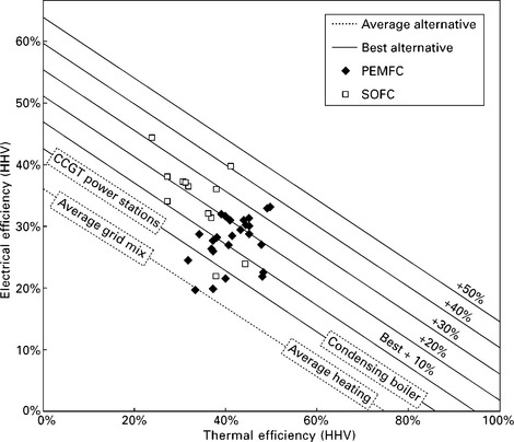
10.5 Thermal and electrical efficiency of fuel cell CHP systems, plotted against lines that connect the electrical and thermal efficiency of the traditional alternatives available in the UK. Reproduced from Staffell (2010).
An aspect of generating efficiency that is often overlooked is the energy that is consumed in the process of producing power. For example, power stations in the UK consume 2% (gas), 5% (coal) and 9% (nuclear) of the electricity they generate (MacLeay et al., 2008), and electricity consumption by condensing boilers and renewable microgeneration can prove to be significant (Staffell et al., 2010; Carbon Trust, 2007). This is also the case with fuel cell micro-CHP systems, as energy is required by the pumps, fans, inverter, system controller and fuel processor; all of which is neglected if only the stack is considered in isolation. These additional losses reduce the electrical efficiency of a whole system by one-fifth to one-third, as illustrated by the example in Fig. 10.6.
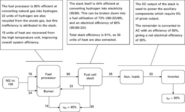
10.6 A typical breakdown of the overall efficiency of a micro-CHP system. Reproduced from Staffell (2010).
Leading SOFC systems have demonstrated electrical efficiencies as high as 40-50% HHV when operating on natural gas (New Energy Foundation, 2010; Todo et al., 2008; Ceramic Fuel Cells Limited, 2009). Their efficiency in real-world operation is somewhat lower though, with average efficiencies of 35% electrical and 71-74% total seen during residential demonstrations in Japan (New Energy Foundation, 2010).
Fuel processing incurs greater losses in low temperature PEFC systems, and so electrical efficiencies are lower than for SOFCs. Large-scale demonstrations in both Japanese and German homes have shown that 27-32% electrical, and 70-75% total efficiency can be consistently achieved (New Energy Foundation, 2009; Franke, 2010).
10.4.2 Effects of dynamic operation
The average efficiencies experienced during field trials are typically 2-6% lower than the values quoted by manufacturers, which are measured at steady state when operating at full power. The dynamic nature of energy demand from individual homes means that fuel cells cannot always operate at their peak efficiency, and that energy is wasted in starting and stopping the unit and by generation occurring when there is no demand from the house. Electrical efficiencies in particular are profoundly influenced by the operating pattern of the CHP device over the course of time, which makes real-world performance diverge from that of controlled laboratory tests (Kuhn et al., 2008).
Part load performance
Most technologies have a lower efficiency when run at partial load, either due to incomplete fuel combustion or higher ancillary power drains (Ida, 2008; Thomas, 2008; Beausoleil-Morrison, 2007), and this is also the case for fuel cells as explained in Section 10.2. Systems are usually operated well below their peak power to improve their durability and efficiency, so in practice when power output decreases, the electrical efficiency also declines. Figure 10.7 plots the electrical and thermal efficiency of 12 different fuel cell systems (as opposed to stacks) at different levels of power output. It is clear that across nearly all PEFC and SOFC products, electrical efficiency falls as power output decreases, and the thermal efficiency of domestic-scale systems is either constant or also falls.
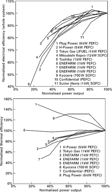
10.7 Whole system electrical and thermal efficiency (including fuel processing, inverter and parasitic loads) of different fuel cell CHP systems, measured against power output. The efficiency of each system is presented relative to its full-power efficiency (Staffell, 2010).
On/off cycling and start-up
Low temperature fuel cells are expected to operate intermittently in people's homes, starting up and shutting down on most days in response to levels of demand (Hamada et al., 2006; Osaka et al., 2005). Many SOFCs are not able to cope with this due to the materials degradation caused by thermal cycling, and so current systems have to operate continuously.
Electricity is required during start-up and shut-down procedures to power the pumps, blowers and electronic systems which provide adequate stack conditions. A long period of pre-heating is also required to raise the generator's mass up to operating temperature. Although PEFC stacks may be able to operate from ambient temperature, the fuel processor must be heated to several hundred degrees before hydrogen can be produced.
The amount of energy required to start a fuel cell micro-CHP system over the course of a year has not been widely studied; however, it is thought to be significantly greater than for other micro-CHP technologies. A 12-month field trial of a Baxi Beta (Staffell, 2010) and laboratory tests on a Vaillant system (Arndt, 2007) (both PEFC) suggest that 1-2 kWh of natural gas are required per kWe of capacity each time the fuel cell is started from cold. In comparison, the Carbon Trust estimated that 0.5 kWh of heat and 75 Wh of electricity is required by a Stirling engine, and condensing boilers incur a penalty of 0.17 kWh gas consumption for every start-up (Carbon Trust, 2007).
The gas consumed in pre-heating the fuel cell system is effectively wasted, as the heat embodied in the generator is not transferred to the house in useful ways (Kuhn et al., 2008). Systems are typically located away from the main living areas of the house due to constraints on space or noise. Most systems are located in basements, garages or outside, where any heat lost through radiation or conduction will be useless. If the fuel cell is located in an occupied area of the house, any heat dissipated to the surroundings will be of use during the heating season, but will be unwanted during the summer months when only hot water is required.
The annual seasonal efficiency of the fuel cell (as reported in field trials) will therefore be lower than when measured at steady state, as the additional gas and electricity consumed during start-up and shut-down will be accounted for. In the Baxi field trial, pre-heating the system accounted for 3% of the total consumption, and so is not a negligible effect. Two additional consequences are that system efficiencies will be slightly higher during winter months when longer periods of heating are required, and that fuel cells will be better suited to houses with higher demands for space heating which can guarantee fewer on-off cycles (Carbon Trust, 2007).
Utilisation of generated energy
The production of electricity and heat in a fuel cell are inseparably linked, and the heat-to-power ratio of most fuel cell systems lies between 0.8 and 1.6 (excluding the auxiliary burner). The relatively inflexible operation of micro-CHP systems therefore means that much of the energy they generate can go to waste if there is insufficient storage capacity. The always-on SOFC systems trialled in Japan have suffered particularly due to the combination of limited thermal demand in Japanese homes, and the use of small 70 L storage tanks. Even though the units operated with 36-39% thermal efficiency, nearly half of the heat they generated was dumped to the atmosphere, meaning the thermal utilisation efficiency averaged only 23%. These issues and a similar loss of performance relative to manufacturers' specifications were reported in the only published field trial of a PEFC system in a UK house (Staffell, 2010), again raising the issue of correctly sizing and siting these technologies.
10.4.3 Reliability, availability and lifetime
The functional lifetime is a crucial and contentious issue for the commercialisation and economic viability of fuel cell micro-CHP systems, and is one of the characteristics which varies most between designs. The high capital cost of the fuel cell stack means that frequent replacement is not economically justifiable, and the impact of gradual degradation on the efficiency can have serious impacts on the output and thus value of the system (Hawkes et al., 2009b). The industry-wide target of 40 000 hours continuous operation has remained elusive for nearly a decade (Larminie and Dicks, 2003; Horwitz, 2008), only being attained in the field by industrial-scale PAFC systems from UTC and Fuji. Figure 10.8 shows that the demonstrable lifetime of PEFC systems is gradually moving towards this target, but SOFC and AFC appear to have stagnated with openly published reports of stack tests not lasting for more than 10 000-20 000 hours for SOFC, or 5000-10 000 hours for AFC.
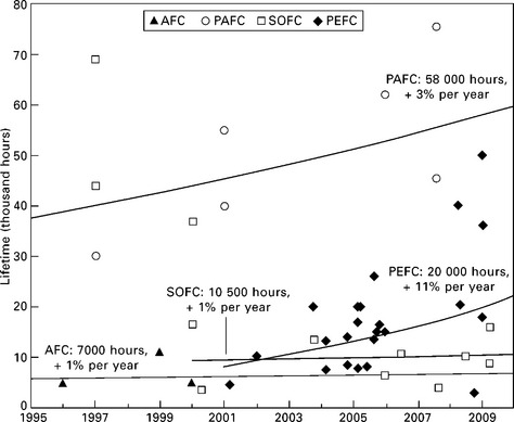
10.8 The improvement in demonstrated stack and system lifetimes of different fuel cell technologies over the past 15 years. Data points indicate individual results reported in the literature, and weighted exponential fits are shown for each technology, with a label giving the rate of improvement, and estimated average lifetime as of 2009.
Japanese manufacturers of ENE-FARM systems expect that their latest generation of PEFC stacks is now able to meet the 40 000 hour target (Panasonic Corporation, 2008); however, as none of these units have been operating for more than two years in the field it is impossible to verify their claims yet. The longest reported lifetimes so far from the Japanese field trials have been around 20 000 hours (FuelCell Japan, 2008; Tabata et al., 2009; Homma, 2008; Bessho, 2008).
The longest SOFC lifetimes were demonstrated by Siemens-Westinghouse in the late 1990s (George, 1997; Hoogers, 2002). Evaluations of fuel cells which are based on this achievement make the leap of faith that if two cells can operate at steady state in a laboratory for 69 000 hours, then a complete system in the dynamic environment of a house should be able to as well (Pehnt and Fischer, 2006). The preceding decade of research has not managed to achieve this stiff technical challenge, and system lifetimes have remained under 15 000 hours since. The latest Japanese roadmap for SOFC technology predicts that 10 000-20 000 hour lifetimes should be attainable by 2015, and that 40 000 hours is not expected until after 2020 for domestic systems (New Energy Foundation, 2010; Kogaki, 2007). Although manufacturers outside of Japan are more optimistic about these time scales, none have yet demonstrated a product that is close to achieving these targets (Dow, 2009; Hexis, 2007).
Currently, both PEFC and SOFC stacks lose power at a rate between 0 and 5% per thousand hours, depending on the design and materials used by each manufacturer (Staffell, 2009; de Bruijn et al., 2008). Reduced catalytic activity in the cells and reformer, combined with increasing cell resistance causes a gradual drop in output voltage, and thus power output. This can shorten stack lifetime, but mechanical deterioration of the cells is usually the limiting factor.
Large-scale field trials have revealed that the reliability of micro-CHP systems falls short of expectations, and that the fuel cell stack no longer requires the greatest attention. These complex systems are currently filled with novel and relatively untried components, which has resulted in relatively simple problems causing numerous forced shutdowns. Analysis of nearly 1000 PEFC and SOFC systems has shown that the mean time between failure (MTBF) is currently in the region of 5-10 000 hours, meaning that most systems experienced at least one failure per year (New Energy Foundation, 2009; 2010). Tentative data suggest that MTBF has increased substantially (towards 30 000 hours) now that these systems have been commercially launched, and so are produced on a larger scale and have become more standardised; however, this will need to be confirmed once more recent data are released.
10.5 Commercial development and future trends
Fuel cells have been under development for the past 30-50 years, but are still relatively immature in commercial markets. Fuel cells are often seen as lagging behind other micro-CHP technologies, 'forever 5 years away from commercialisation' (Kho, 2005; Rechtin, 2006; O'Sullivan, 2006). However, Japanese manufacturers began to roll the first units off automated production lines in 2009, marking the long-awaited transition towards mass production. With over 10 000 domestic micro-CHP units already operating in Japan and annual sales expected to double this in 2011, the commercialisation of fuel cells has already begun.
A survey of small stationary fuel cell developers showed that of the 11 000 CHP and backup-power systems installed up until 2009, 85% were based on PEFCs, and the remainder were SOFCs (Adamson, 2009).
10.5.1 Major manufacturers, products and demonstrations
Three countries are leading the demonstration and commercialisation of fuel cells: Japan, Germany and South Korea. The USA is a key player in the fields of industrial-CHP and fuel cell vehicles, but has seen little development of domestic scale CHP due to an unattractive financial and regulatory landscape.
A series of large-scale demonstration programmes have been carried out in Japan since 2002, and have so far resulted in the installation of 3352 PEMFC and 210 SOFC units into public homes (New Energy Foundation, 2010). The ENE-FARM brand of PEFC systems were launched after these trials, emerging from extensive collaboration between Panasonic, ENEOS (Sanyo) and Toshiba. They are based on PEFC stacks ranging from 0.7 to 1.0 kWe electrical output (0.9-1.4 kWth) and are packaged with a fuel processor for either natural gas, LPG or kerosene, and a hot water tank with integrated boiler.
ENE-FARM is the culmination of over a decade of collaborative research and demonstration by Japanese fuel cell manufacturers and energy distribution companies, who respectively produced the stacks and fuel reformers. These companies agreed to collaborate on the development and commercialisation of the ENE-FARM in the realisation that the problems that had to be overcome were too great for one company to achieve alone. System manufacturers decided on, and then published specifications for standardised balance of plant (BoP), and individual companies then openly competed to develop these components (Ueda, 2007). This collaborative strategy attained an almost four-fold decrease in BoP costs, whilst improving durability and readying the whole supply-chain for mass production (Tanaka, 2008).
Japan is also at the forefront of SOFC development with companies such as Kyocera, Nippon Oil and TOTO engaged in residential demonstrations of their 1 kWe-class micro-CHP systems. Despite the vastly different stack operation, these devices are externally similar to the ENE-FARM, with a small unit containing the stack, fuel processor and electronics, and a hot water tank and backup burner packaged separately. The government roadmap aims for fundamental materials research and residential demonstrations to continue until at least 2012 before commercialisation in 2015-2020 (New Energy Foundation, 2010).
In Germany, the Callux residential field trials began in 2008 with three manufacturers: Baxi Innotech (PEMFC), Hexis and Vaillant (both SOFC). Approximately 100 units have been installed so far, and a total of 800 will be installed by 2012, and operated for up to three years in German homes (Franke, 2010).
Elsewhere, Ceramic Fuel Cells (Australia), Acumentrics (USA), Hyosung (S. Korea), GS Fuel Cell (S. Korea), Plug Power (USA) and Ceres Power (UK) all have active programmes for fuel cell CHP systems and most plan to commercialise in the early 2010s.
10.5.2 Current and future costs
Fuel cells are the most expensive form of micro-CHP at present. There is still limited information on the price of most systems, due to commercial secrecy and low production volumes. Between 2005 and 2009, the average price of 0.75-1 kWe ENE-FARM systems decreased from £36 000 for early demonstrations to £15 500 at the time of commercial launch (Staffell and Green, 2009). In comparison, leading SOFC demonstration systems from Hexis and Kyocera cost a minimum of £30 000 for 0.7 and 1.0 kWe systems (Yamamoto, 2008; Singhal, 2007). It must be remembered that these are pre-commercial designs produced by skilled engineers rather than production lines, so mass production will bring with it substantial cost reductions. However, it is expected that ten years of deployment and cost reduction is required before unsubsidised prices reach £5 000 per kWe (Staffell and Green, 2009).
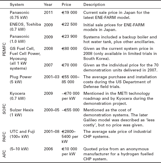
Table 10.2 presents the actual sale prices of seven models of fuel cell system which were collated in Staffell (2010). No clear trend can be seen between technologies, as the differences in price are currently dominated by production volumes and system capacity. Excluding the larger PAFC and AFC systems, it is clear that ENE-FARM are offered at the lowest price, which is understandable as they are the most commercially developed micro-CHP system.
Table 10.2
Known sale prices for fuel cell micro-CHP systems. All prices have been converted to 2009 Euros with the following exchange rates: ¥145, $0.80, 1325 won to €1, and 2.5% annual inflation
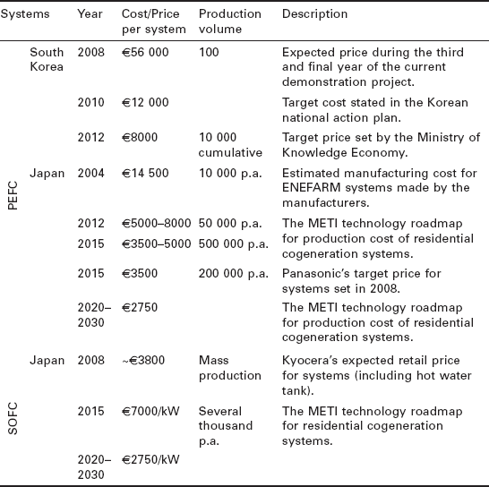
In addition to publishing current prices, the manufacturers and agencies involved in the leading fuel cell demonstrations have laid out their expectations and targets for each technology, which are summarised in Table 10.3 (Staffell, 2010). It could be argued that these manufacturers are best placed to make predictions as they currently have the most experience with commercialising micro-CHP systems. The projections in Table 10.3 are substantially higher than those given by other sources; they are both closer to current sale prices, and have far less aggressive timetables for cost reduction. A striking feature is that neither the Japanese government, nor the manufacturers of PEFC or SOFC systems expect prices to fall below ¥400 000 (£2000) even in 10-20 years' time.
10.6 Sources of further information and advice
Nice and Strickland (2009) and Merewether (2005) give an overview of fuel cell theory, while Rayment and Sherwin (2003) and Larminie and Dicks (2003) provide a rich and detailed discussion. Further information on the different components of fuel cell systems is available in the literature (Garche and Jörissen, 2003; Blomen and Mugerwa, 1994).
10.7 References
Available at Adamson, K.-A. Fuel Cell Today Small Stationary Survey. accessed May 2009. http://www.fuelcelltoday.com/online/surveys, 2009.
Ang, S.M.C., Brett, D.J.L., Fraga, E.S. A multi-objective optimisation model for a general polymer electrolyte membrane fuel cell system. Journal of Power Sources. 2010; 195(9):2754–2763.
Arndt, U. Investigation of a Vaillant Fuel Cell Euro 2 at the Technical University of Munich. In: Beausoleil-Morrison I., ed. Experimental Investigation of Residential Cogeneration Devices and Calibration of Annex 42 Models. International energy agency, 2007.
Ball, S., Thompsett, D., Ultra CO Tolerant PtMo/PtRu anodes for PEMFCs. solid state Ionics. Materials for Fuel Cells and Fuel Processors. 2002
Beausoleil-Morrison, I. Experimental Investigation of Residential Cogeneration Devices and Calibration of Annex 42 Models. A Report of Subtask B of FC + COGEN-SIM. International energy agency.. 2007.
Bessho, T. New Models of Residential PEMFC Cogeneration Systems. Fuel Cell Seminar & Exposition. Phoenix, Arizona. Available at http://tinyurl.com/mm3nng, 2008.
Blomen, L.J.M.J., Mugerwa, M.N.Fuel Cell Systems. springer, 1994.
Brett, D.J.L., Aguiar, P., Brandon, N.P., Kucernak, A.R. Measurement and modelling of carbon monoxide poisoning distribution within a polymer electrolyte fuel cell. International Journal of Hydrogen Energy. 2007; 32:863–871.
Brett, D.J.L., Atkinson, A., Brandon, N.P., Skinner, S.J. Intermediate temperature solid oxide fuel cells. Chemical Society Reviews. 2008; 37(8):1568–1578.
Trust, Carbon. Micro-CHP Accelerator: Interim Report. Available at http://tinyurl.com/lrlmd9, 2007.
Ceramic Fuel Cells Limited. BlueGEN: Modular Generator - Power + Heat. Available at http://tinyurl.com/paxjh4, 2009. [accessed August 2009].
Colella, W.G. Combined Heat and Power Fuel Cell Systems. PhD thesis, Department of Engineering science, University of Oxford.. 2002.
Das, D., Veziroglu, T.N. Hydrogen production by biological processes: a survey of literature. International Journal of Hydrogen Energy. 2001; 26(1):13–28.
De Bruijn, F.A., Dam, V.A.T., Janssen, G.J.M. Review: durability and degradation issues of PEM fuel cell components. Fuel Cells. 2008; 8(1):3–22.
Dorer, V., Weber, R., Weber, A. Performance assessment of fuel cell micro-cogeneration systems for residential buildings. Energy and Buildings. 2005; 37(11):1132–1146.
Dow, B. Company Update. Ceramic Fuel Cells Limited. Available at http://tinyurl.com/mc3b4y, 2009.
Echigo, M., Shinke, N., Takami, S., Tabata, T. Performance of a natural gas fuel processor for residential PEFC system using a novel CO preferential oxidation catalyst. Journal of Power Sources. 2004; 132(1-2):29–35.
Franke, A. Baxi Innotech: PEM fuel cells for the Callux programme. Birmingham, UK: Hyrdogen & Fuel Cells for Clean Cities; 2010.
Japan, FuelCell. 20,000 Hours = Continuous Run Time of JOMO's Residential FC Cogeneration System. Available at http://www.fcpat-japan.com/News2008–3.html#73, 2008. [accessed September 2008].
Garche, J., Jörissen, L., PEMFC fuel cell systems'Vielstich W., Lamm A., Gasteiger H.A., eds. Handbook of Fuel Cells - Fundamentals, Technology and Applications. Technology and Applications; 4. John Wiley & Sons, 2003.
George, R.A. SOFC Combined Cycle Systems for Distributed Generation. American Power Conference. Chicago. Available at http://tinyurl.com/mhxsg2, 1997.
Ghouse, M., Abaoud, H., Al-Boeiz, A. Operational experience of a 1 kW PAFC stack. Applied Energy. 2000; 65:303–314.
Hamada, Y., Goto, R., Nakamura, M., Kubota, H., Ochifuji, K. Operating results and simulations on a fuel cell for residential energy systems. Energy Conversion and Management. 2006; 47(20):3562–3571.
Harrison, J. What is Microgeneration? Claverton Energy Group Conference. Bath, UK. Available at http://www.claverton-energy.com/what-is-microgeneration.html, 2008.
Hawkes, A.D., Staffell, I., Brett, D., Brandon, N. Fuel cells for micro-combined heat and power generation. Energy & Environmental Science. 2009; 2:729–744.
Hawkes, A.D., Brett, D.J.L., Brandon, N.P. Fuel cell micro-CHP techno-economics: Part 2-Model application to consider the economic and environmental impact of stack degradation. International Journal of Hydrogen Energy. 2009; 34(23):9558–9569.
Hexis. Swiss company Hexis tests fuel cell system in the field. Available at http://tinyurl.com/mx7nfz, 2007. [accessed July 2009].
Homma, T. The latest Fuel Cell news in Japan, June 2008. Available at http://www.fcdic.com/eng/news/200807.html#3, 2008. [accessed October 2008].
Hoogers, G. Fuel Cell Technology Handbook. CRC Press, 2002.
Horwitz, J. Fuel Cell mCHP on the Threshold of Success. Fuel Cell Seminar & Exposition. Phoenix, Arizona. Available at http://tinyurl.com/mqp9bx, 2008.
Hubert, C.-E., Achard, P., Metkemeijer, R. Study of a small heat and power PEM fuel cell system generator. Journal of Power Sources. 2006; 156(1):64–70.
Ida, H. Optimization of Japanese heat pump systems in the moderate climate region. 9th IEA Heat Pump Conference. Zürich, Switzerland. Available at http://tinyurl.com/ykl2dre, 2008.
Independant Power Technologies Ltd. PULSAR-6 Product Brochure. Moscow. 2006;
Kho, J. Fuel Cell Follies. Red Herring. San Mateo, California. Available at http://www.redherring.com/Home/14402, 2005.
Kiros, Y., Myrén, C., Schwartz, S., Sampathrajan, A., Ramanathan, M. Electrode R&D, stack design and performance of biomass-based alkaline fuel cell module. International Journal of Hydrogen Energy. 1999; 24(6):549–564.
Kogaki, T., Japan's Approach to the Commercialization of Fuel Cell and Hydrogen Technology. Seminar & Exposition. 2007. http://tinyurl.com/lnue32 [San Antonio, USA, Available at].
Kolb, G.Fuel Processing: for Fuel Cells. Wiley, 2008.
Kuhn, V., Klemes, J., Bulatov, I. MicroCHP: overview of selected technologies, products and field test results. Applied Thermal Engineering. 2008; 28(16):2039–2048.
Larminie, J., Dicks, A.Fuel Cell Systems Explained. John Wiley & sons, Ltd, 2003.
Lindstrom, B., Karlsson, J.A.J., Ekdunge, P., De Verdier, L., Häggendal, B., Dawody, J., Nilsson, M., Pettersson, L.J. Diesel fuel reformer for automotive fuel cell applications. International Journal of Hydrogen Energy. 2009; 34(8):3367–3381.
Lohsoontorn, P., Brett, D.J.L., Brandon, N.P. The effect of fuel composition and temperature on the interaction of H2s with nickel-ceria anodes for solid oxide fuel cells. Journal of Power Sources. 2008; 183(1):232–239.
Lohsoontorn, P., Brett, D.J.L., Brandon, N.P. Thermodynamic predictions of the impact of fuel composition on the propensity of sulphur to interact with Ni and ceria-based anodes for solid oxide fuel cells. Journal of Power Sources. 2008; 175(1):60–67.
MacLeay, I., Harris, K., Michaels, C.Chapter 5: Electricity'. Digest of UK Energy Statistics. National statistics, 2008.
Marquez, A.I., Ohrn, T.R., Trembly, J.P., Ingram, D.C., Bayless, D.J. Effects of coal syngas and H2s on the performance of solid oxide fuel cells: Part 2. stack test. Journal of Power Sources. 2007; 164(2):659–667.
Merewether, E.A. Alternative Sources of Energy - An Introduction to Fuel Cells. US Geological Survey Bulletin 2179. Available at http://pubs.usgs.gov/bul/b2179/, 2005.
New Energy Foundation. Report data from the Large Scale Residential Fuel Cell Demonstration Project in 2008. Available at http://happyfc.nef.or.jp/pdf/20fc.pdf, 2009. [(in Japanese)].
New Energy Foundation. Solid Oxide Fuel Cell Empirical Research. Available at http://sofc.nef.or.jp/topics/pdf/2010_sofc_houkoku.pdf, 2010. [(in Japanese)].
Nice, K., Strickland, J. How Fuel Cells Work. Available at http://tinyurl.com/ltsu5y, 2009. [accessed June 2009].
O'Sullivan, J.B. Fuel cells: The last 45 + years. Fuel Cell Seminar & Exposition. Honolulu, Hawaii. Available at http://tinyurl.com/nbsxr4, 2006.
Osaka, N., Nishizaki, K., Kawamura, M., Ito, K., Fujiwara, N., Nishizaka, Y., Kitazawa, H. Development of Residential PEFC Co-generation Systems. Fuel Cell Seminar & Exposition. Palm Springs, California. Available at http://tinyurl.com/nbko3c, 2005.
Panasonic Corporation. Panasonic Develops New Fuel Cell Cogeneration System for Home Use. Available at http://tinyurl.com/5fk325, 2008. [accessed June 2009].
Pehnt, M., Fischer, C. Environmental Impacts of Micro Cogeneration. In: Cames M., Fischer C., Praetorius B., Schneider L., Schumacher K., Voβ J.-P., eds. Micro Cogeneration: Towards Decentralized Energy Systems. springer, 2006.
Penfold, D. A Dual Anaerobic System for Bioremediation of Metal and Organic Waste. PhD Thesis, school of Biosciences, University of Birmingham.. 2004.
Rayment, C., Sherwin, S. Introduction to Fuel Cell Technology. University of Notre Dame, USA. Available at http://tinyurl.com/ndghpk, 2003.
Rechtin, M. Fuel cell vehicles? Don't hold your break; Somehow, success always seems to be just 20 years away. Arkon, Ohio: Tire Business; 2006.
Redwood, M.D. Bio-hydrogen and biomasss-supported palladium catalyst for energy production and waste-minimisation. PhD Thesis, school of Biosciences, University of Birmingham.. 2008.
Schmidt, D.S. Status of the Acumentrics SOFC Program. Fuel Cell Seminar & Exposition. Honolulu, Hawaii. Available at http://tinyurl.com/lhy3or, 2006.
Singhal, S.C. Innovative Solid Oxide Fuel Cell Systems for Small Scale Power Generation. Tenth Grove Fuel Cell Symposium. London: UK; 2007.
Song, C. Fuel processing for low-temperature and high-temperature fuel cells: challenges, and opportunities for sustainable development in the 21st century. Catalysis Today. 2002; 77(1-2):17–49.
Spiegel, R.J., Preston, J.L., Trocciola, J.C. Fuel cell operation on landfill gas at Penrose Power Station. Energy. 1999; 24(8):723–742.
Staffell, I. A review of small stationary fuel cell performance. Available at http://wogone.com/iq/review_of_fuel_cell_performance.pdf, 2009.
Staffell, I. Fuel cells for domestic heat and power: Are they worth it?. PhD Thesis, Chemical Engineering, University of Birmingham. Available at http://etheses.bham.ac.uk/641/, 2010.
Staffell, I., Green, R.J. Estimating future prices for stationary fuel cells with empirically derived learning curves. International Journal of Hydrogen Energy. 2009; 34(14):5617–5628.
Staffell, I., Green, R., Kendall, K. Cost targets for domestic fuel cell CHP. Journal of Power Sources. 2008; 181(2):339–349.
Staffell, I., Barton, J., Blanchard, R., Hill, F., Jardine, C., Brett, D., Baker, P., Brandon, N., Hawkes, A., Infield, D., Kelly, N., Leach, M., Matian, M., Peakcock, A., Sudtharalingam, S., Woodman, B. UK Microgeneration. Part II: Technology Overviews. Proceedings of the Institute of Civil Engineers. Energ. 2010; 163(4):143–165.
Tabata, T., Yamazaki, O., Shintaku, H., Oomori, Y. Degradation Factors of Polymer Electrolyte Fuel Cells in Residential Cogeneration Systems. In: Büchi F.N., Inaba M., Schmidt T.J., eds. Polymer Electrolyte Fuel Cell Durability. Springer, 2009.
Tanaka, R. Update on Residential Fuel Cells Demonstration and Related Activities in Japan. Fuel Cells KTN: Fuel cells for distributed generation. Available at http://tinyurl.com/qqpp2s, 2008.
Thomas, B. Benchmark testing of Micro-CHP units. Applied Thermal Engineering. 2008; 28(16):2049–2054.
Todo, Y., Ishikawa, H., Uematsu, H., Gonda, I., Sumi, H., Okuyama, Y., Usui, Y., Komatsu, D., Furusaki, K. Development of Solid Oxide Fuel Cells at NGK Spark Plug Co., Ltd. Fuel Cell Seminar & Exposition. Phoenix, Arizona. Available at http://tinyurl.com/n3c36e, 2008.
Ueda, T. Japan's Approach to the Commercialization of Fuel Cell/Hydrogen Technology. 7th Steering Commitee Meeting. Sao Paulo, Brazil, International Partnership for the Hydrogen Economy. Available at http://tinyurl.com/m9dtr5, 2007.
Uribe, F.A., Valerio, J.A., Garzon, F.H., Zawodzinski, T.A. PEMFC reconfigured anodes for enhancing CO tolerance with air bleed. Electrochemical and Solid-State Letters. 2004; 7(10):A376–A379.
Utley, J.I., Shorrock, L.D. Domestic Energy Fact File. London, BRE. Available at http://tinyurl.com/y95fxpu, 2008.
Wakayama, T., Miyake, J. Hydrogen from Biomass. In: Miyake J., Matsunaga T., Pietro A.G.S., eds. Biohydrogen II: An Approach to Environmentally Acceptable Technology. Elsevier, 2001.
Woods, R.R., Cuzens, J.E. Autothermal Reforming of Natural Gas: A Key Technology for Fuel Cells. International Gas Research Conference (IGRC 2001). Amsterdam. Available at http://tinyurl.com/kvwacw, 2001.
Xuan, J., Leung, M.K.H., Leung, D.Y.C., Ni, M. A review of biomass-derived fuel processors for fuel cell systems. Renewable and Sustainable Energy Reviews. 2009; 13(6-7):1301–1313.
Yamamoto, A. Activities toward Commercialization of Fuel Cell/Hydrogen Technology in Japan. Fuel Cell Seminar & Exposition. Phoenix, Arizona. Available at http://tinyurl.com/mz3rov, 2008.
Yasuda, I., Miura, T., Fujiki, H., Komiya, J., Shirasaki, Y., Seki, T., Development of Highly-Efficient and Compact Fuel Processors for PEFC Applications Available at. International Gas Research Conference (IGRC 2001). Amsterdam. 2001. http://tinyurl.com/knpevo
Zhang, J., Xie, Z., Zhang, J., Tang, Y., Song, C., Navessin, T., Shi, Z., Song, D., Wang, H., Wilkinson, D.P., Liu, Z.-S., Holdcroft, S. High temperature PEM fuel cells. Journal of Power Sources. 2006; 160(2):872–891.
1PEFC is also referred to in the literature as PEMFC (proton exchange membrane) and SPFC (solid polymer).
2By bringing UK houses up to the German ‘Passive House’ standard, space heating requirements could be reduced from around 11 MWh to 1 MWh per year. This would give an annual heat demand of 4-6 MWh per year including hot water, which could be provided by a 1 kW fuel cell alone (Utley and Shorrock, 2008; Dorer et al., 2005).