
Heat-activated cooling technologies for small and micro combined heat and power (CHP) applications
Abstract:
This chapter covers the technologies available for small-scale combined heat and power (CHP) systems to utilize recovered heat for air conditioning or refrigeration purposes. Five classes of technology are described and discussed within the context of small-scale CHP: (1) solid desiccant dehumidification, (2) liquid desiccant dehumidification, (3) adsorption (solid adsorbent-based) heat pumps, (4) absorption (liquid absorbent-based) heat pumps, and (5) steam ejector cycles. In this context of small-scale CHP, performance metrics for each class of system are discussed, and performance comparisons are made to the ‘baseline’ systems most commonly used to provide air conditioning and refrigeration today.
11.1 Introduction
Although heat-activated cooling has been used for well over a century, and even predates vapor compression systems in its development, today the majority of space cooling and refrigeration is provided by vapor compression systems. Decades of intense development and deployment of vapor compression systems has led to efficient and affordable products. However, at sites where CHP is put in place, improved energy efficiency, reduced emissions and cost advantages can be realized by utilizing heat-activated cooling.
This chapter focuses on equipment which can utilize the thermal byproducts of small-scale power generation in order to generate a chilled working fluid for space cooling and/or refrigeration, all with a minimal usage of electrical power. 1Further, since electricity generation consumes high grade heat and makes available low grade (or ‘ waste’) heat, cooling equipment that makes use of low grade heat is emphasized.
Beginning with an introductory overview of small-scale trigeneration (11.2), this chapter then describes the available types of systems and some of their applications (11.3-11.6). In order to evaluate the energy consumption of these systems, appropriate performance metrics must be defined. Along with a discussion of such metrics, illustrative comparisons are made between heat-activated cooling technologies (HACT) and their more common ‘baseline system’ counterparts (11.7-11.8). Finally, the advantages and limitations are summarized (11.9), future trends in HACT are discussed (11.10), and further sources of information are provided (11.11).
11.2 Introduction to small-scale trigeneration
Trigeneration is the use of a single fuel source to simultaneously provide heating, cooling and electrical or mechanical power. This chapter deals with technologies that provide cooling with a primary input of heat. More specifically, the heat source is heat recovered as a co-product of electricity generation, and the cooling can be space cooling or refrigeration (or a combination). This means that the cooling device’s driving heat source is at a relatively low temperature: typically 60-120 °C (140-250 °F) for small- scale CHP units. Generally, industrial installations recover heat as saturated or superheated steam, while residential units recover heat as liquid water well below the boiling point at atmospheric pressure. Although some large engines are designed to be water cooled with low-pressure steam (ebullient systems), cooling jacket temperatures for small internal combustion engines are generally in the range of 65-85 °C (150-185 °F).
Due to the ‘ single-input, multiple-output’ nature of trigeneration, and due to the variety of outputs, accounting for the fuel efficiency of such systems is more complicated than for ‘single-input, single-output’ devices. The simplest system-wide metric is the overall fuel utilization rate (sometimes called the ‘combined efficiency’ or ‘overall efficiency’). This metric is based on the First Law of Thermodynamics, and is defined as all useful energy products divided by the fuel input, giving a value that is always between 0 and 1. 2 For the heat-activated component of a trigeneration system, the simplest metric is the thermal coefficient of performance, or thermal COP. This is also a First Law calculation, dividing the useful cooling energy by the heat input energy (sometimes also accounting for electrical parasitics). However, since the thermal COP is bounded by the Second Law of Thermodynamics, it does not necessarily have to be less than 1. These metrics, as well as more sophisticated ones, are discussed in Sections 11.7 and 11.8.
While there is no universally accepted definition of ‘small’ in this context, the term ‘small-scale’ can be taken to apply to installations producing less than 100 kW of electric power. However, 100 kW installations have a lot in common with larger, typically industrial installations, and heat- activated cooling products and information for these applications (such as large absorption chillers) are widely available. On the other hand, microscale devices (under ~5 kW in electrical output), have unique properties, challenges, and requirements, with comparatively few products and little information are available on them. Additionally, micro-scale CHP systems (those providing only heat and electric power) have seen a recent surge in installations, particularly in Japan, Germany and the UK where governments have recognized a role for residential CHP in increasing energy efficiency. Thus a new market for micro-heat-activated technologies is being created. For all these reasons, this chapter makes a special effort to address technologies appropriate for micro-trigeneration.
11.2.1 Prime movers
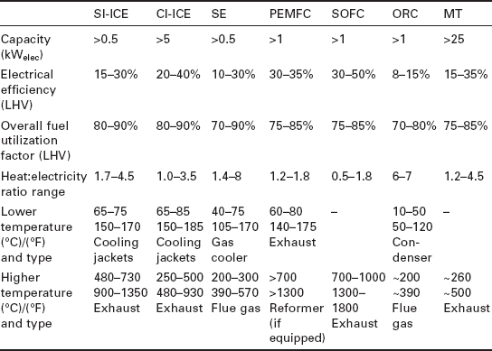
There is a wide variety of prime movers being used and developed for small CHP applications. The most commonly used technologies for micro-CHP are the spark ignition reciprocating internal combustion engine (SI-ICE) and, for systems over a few tens of kWelec, microturbines (MT) and compression ignition engines (CI-ICE). Intense development and rapid improvements are being seen in Stirling engines (SE) and both proton exchange membrane fuel cells (PEMFC) and solid oxide fuel cells (SOFC). Additionally, organic Rankine cycle (ORC) systems are under development. For the external combustion systems (Stirling and ORC), fuel flexible operation (including biofuels) and hybrid solar/fuel-fired systems are being explored. Data important to CCHP are shown for each of these prime movers in Table 11.1, including the typical sizes, efficiencies and heat recovery temperatures.
The primary heat recovery options for most prime mover technologies include two sources of comparable magnitude and widely different temperatures (such as the cooling jackets and exhaust for an ICE, or the cold side cooling fluid and burner flue gas for a Stirling engine). Additional minor contributions to heat recovery can be made by water-cooling the lubricating oil, water- cooling the alternator/generator, and carefully insulating the cabinet to capture heat radiated and convected from the engine. These minor contributions can add up to an additional 10-15% of the fuel energy being captured.
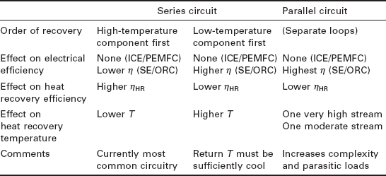
A discussion of the available temperatures of heat recovery is very important when considering heat-activated heat pumps, because each of these devices has some minimum and some optimal driving heat temperature, as discussed in Section 11.3. There are several options for capturing the available heat, and all involve tradeoffs between temperature and efficiency: in general, the higher the heat recovery temperature, the less heat will be recovered, but the more value the heat will have for driving a heat-activated device. In designing a CHP heat recovery system, the heat recovery loop can be a series circuit or two parallel (split-stream) circuits; if a series circuit is chosen, then it can either flow to the high-temperature (e.g. exhaust) component first or last. Since small CHP units on the market today are primarily designed for low temperature, heating season uses, most utilize a series circuitry which cools the high-temperature component first. The tradeoffs are summarized in Table 11.2.
11.2.2 Overview of cooling technologies and applications
Low-grade heat is typically an inevitable byproduct of electricity production. Its capture and distribution are therefore relatively straightforward, requiring only heat exchangers and piping to capture and distribute this heat energy that would otherwise be dissipated to the environment. This straightforward configuration is known as cogeneration or CHP, and a schematic is shown in Fig. 11.1 with numerical values typical of a system based on a small internal combustion engine (ICE).
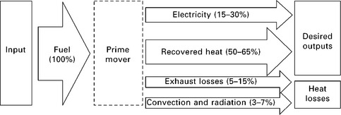
11.1 Energy flow schematic of a generic CHP (cogeneration) system. Numerical efficiency ranges are on an HHV basis; they are representative of a small ICE prime mover with heat recovered from both the exhaust and the cooling jackets, and with cabinet insulation to lessen convection and radiation losses from the prime mover surfaces
On the other hand, using waste heat to cool a working fluid below ambient temperature requires additional equipment. Since three useful products are produced (electricity, usable heat, and space cooling or refrigeration), this is called trigeneration or combined cooling, heat and power (CCHP). The flow of energy involved in CCHP is shown in Fig. 11.2. Note that the heat rejected from the heat-activated cooling device (HACD) is likely still hot enough to be used for preheating domestic hot water (DHW), swimming pool heating, industrial process pre heating, or other uses. However, the amount of heat rejected by the HACD may exceed the demand for such low-grade heat (especially during the cooling season), and thus most is likely to be rejected to the environment. The output region enclosed by dotted lines in Fig. 11.2 indicates this variable utility of the heat rejected from the HACD.
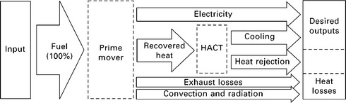
11.2 Energy flow schematic of a generic CCHP (trigeneration) system. Heat rejected from the HACT may still be at a high enough temperature to be useful, e.g. as DHW preheating or swimming pool water heating, or it may be considered a heat loss if rejected directly to the ambient.
The ability to replace electrical consumption with the use of low-grade heat allows a trigeneration system to provide cooling in addition to electricity, without increasing fuel consumption. It also has the advantage of increasing the system utilization rate during the cooling season.
Small-scale installations in the 5-100 kW range generally serve industrial facilities, commercial facilities or larger residential complexes. Micro systems (under 5 kW electric) are generally used for residential or small commercial applications. In general, any of the three energy products produced by a trigeneration system can either be utilized directly at the site of generation or be exported off-site. In the case of small-scale systems, electricity is typically exported easily (by selling electricity back to the grid). Although thermal energy is not usually viable for export in small systems, it is relatively easy to store (e.g. in a hot water tank). On the other hand, electricity storage is generally expensive. For installations independent of the grid, electrical storage is still possible (e.g. in batteries), but as long as a grid is available to absorb the excess electricity, then ‘net metering’ is the most cost-effective and energy efficient solution for dealing with times of excess electricity production.
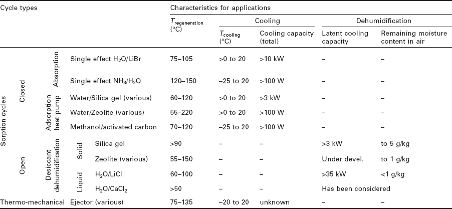
In organizing the discussion of heat-activated cooling devices, a choice must be made between a classification scheme based on applications, and one based on cycle types and working fluids. In the interest of clarity, the sections on system types are organized around cycle types and working fluids, with comments regarding applications incorporated where appropriate. Additionally, Table 11.3 has been provided for easy cross reference between applications and the appropriate corresponding cycle types.
11.3 Types of cooling systems and their applications
Heat-activated cooling technologies can most broadly be classified as either open or closed cycles. In open cycles, atmospheric air is the working fluid, and it is drawn into the system and exhausted out of it with only partial or no recirculation. In closed cycles, the working fluid is circulated repeatedly through the cycle without any loss of mass, allowing various working fluids to be chosen based on their thermodynamic properties, such as water, ammonia, alcohols, hydrocarbons, salt solutions, and other fluids. Open cycles discussed in this chapter are liquid and solid desiccant processes. Closed cycles discussed are absorption, adsorption and steam ejector heat pump cycles.
11.3.1 Background on sorption processes
Nearly all open and closed thermally-driven cycles for cooling and dehumidification rely on sorption processes (with the exception of the thermomechanical ejector cycle). Sorption processes can be divided into absorption and adsorption. In absorption, absorbate molecules are dissolved into (i.e. incorporated into the bulk of) an absorbent material, changing the chemical makeup of the absorbent. On the other hand, the adsorption process involves adhesion of molecules to a surface at a gas-solid interface due to van der Waals (secondary) bonding (e.g. hydrogen bonding), leaving the chemical makeup of the adsorbent unchanged. This means that the absorption capacity of absorbent media scales with absorbent volume; whereas adsorption capacity of adsorbent media scales with interfacial surface area. The sorption rates of both adsorption and absorption processes scale with interfacial surface area, since mass transfer can only occur at the gas-solid or gas-liquid interface.
11.4 Open sorption cycles: desiccant dehumidification
A desiccant material can be an absorbent or an adsorbent. Absorbent desiccant materials are generally aqueous salt solutions, although triethylene glycol has been proposed (water is also used as an absorbent in closed absorption cycles, described in Section 11.5). In contrast, adsorbent desiccant media are created by either (1) using packed beds of solid adsorbent grains or pellets or (2)applying a solid desiccant such as silica gel or activated carbon as a thin coating to high surface area materials such as a honeycomb of aluminum or a finned heat exchanger. The coated finned heat exchanger approach allows heat to be added to (and removed from) the desiccant material by an internal heat transfer fluid such as water, while the packed bed and honeycomb approaches require that an airstream be used to regenerate the desiccant.
Although a wide variety of materials have at least some affinity for water, additional properties are important to make a material practical as a desiccant. Particularly important are (1) a large water capacity per unit weight (and per unit volume) of desiccant material, (2) chemical and physical stability over many cycles of sorption and regeneration, and (3) resistance or immunity to contamination with dust and other contaminants present in the process and regeneration air streams. Additionally, the specific characteristics of the material’s sorption isotherms must match the desired application (e.g. regeneration temperature and desired process air humidity ratio).
There are both liquid and solid hygroscopic materials that make good desiccants. The hygroscopic nature of the sorbent surface lowers the vapor saturation pressure of water at the surface. When the desiccant surface vapor pressure is lower than the partial pressure of water in the air over the surface, sorption of water will take place from the air to the desiccant. Sorption continues until the desiccant becomes saturated (i.e. until the vapor pressure differential between the surface and the surrounding air equalizes, achieving equilibrium). The desiccant can then be dried, or regenerated, by heating it to raise the vapor pressure above the surrounding air’s water vapor partial pressure. By cyclically saturating a desiccant material with moisture from the process air, regenerating (drying) the desiccant material in a heated regeneration air stream (which is exhausted outdoors), and cooling the desiccant with process air for sorption again, moisture can be removed from a building’s process air and exhausted to the surroundings. Three realizations of this basic principle are shown in Fig. 11.3. The primary input of energy to a desiccant system is heat to drive the desorption (regeneration) process, and fortunately the temperature required to regenerate many desiccants (i.e. the temperature of the desiccant isotherm at which the desiccant vapor pressure exceeds the ambient or regeneration water partial pressure) is within reach of small-scale CHP systems.
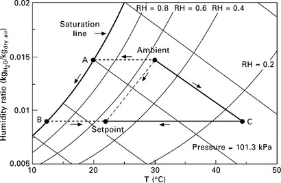
11.3 Airside psychrometric state points for three possible dehumidification processes, all of which cool and dehumidify ambient air to the same setpoint. Path ambient A-B-setpoint: conventional process, which removes moisture by cooling the air along the saturation line and reheating; path ambient-C-setpoint: rotary solid desiccant wheel with sensible-only cooling coil; path ambient-setpoint: liquid desiccant with sorption occurring directly on chilled wet desiccant cooling coils.
11.4.1 Solid (adsorptive) desiccant cycles
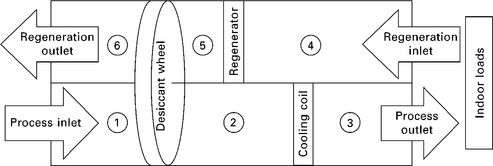
The solid desiccant cycle is typically arranged as a desiccant-coated rotary heat exchanger (commonly referred to as a desiccant wheel) which rotates very slowly through process and regeneration air streams. A basic cycle is shown in Figs 11.4 and 11.5. Since the process air must first cool the desiccant before the desiccant can begin to dehumidify it, the first few degrees of rotation into the dehumidification section are actually devoted to sensible cooling of the desiccant (and the medium to which it adheres or within which it is packed). However, due to the slow rotation speed of the wheel, this has only a small effect on the process air temperature. The outlet air conditions are not uniform around the wheel, but they become homogeneously mixed downstream, and these mixed averages are depicted in Fig. 11.5.
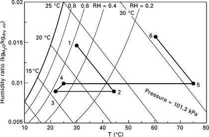
11.5 Air side psychrometric state points for a basic desiccant wheel, for typical indoor and outdoor summer conditions in the Southeastern US. Regeneration inlet is assumed to be outgoing ventilation air.
Solid desiccant materials and substrates
There are many substances that are hygroscopic, but relatively few of these have the large surface area required to serve as a practical desiccant. The surface is where a desiccant actually interacts and exchanges moisture with the surrounding airstream. Thus it makes sense to maximize the surface area of a given volume (or mass) of desiccant material. This is achieved through selecting materials with high porosity.
Several materials have been developed to serve as practical desiccants. An important distinction exists between the zeolites and all other desiccants (such as silica gel, activated carbon, and activated alumina). Zeolites have uniform pore size due to their crystalline pore structure (Ruthven, 1984, p. 9), while the other desiccants have a distribution of pore sizes centered on some mean value. For all desiccant types, typical pore diameters range from a few Angstroms to a few tens of angstroms (Ruthven, 1984, p. 4).
Every desiccant material has a set of equilibrium sorption isotherms with a characteristic shape in a graph of moisture content vs. surface vapor pressure. A qualitative comparison of the equilibrium isotherm shapes for the most common solid desiccants is shown in Fig. 11.6. From this figure, the relative characteristics of each desiccant are apparent. Compared with other water-adsorbing materials, silica gel has the widest operating range (though large swings in surface vapor pressure are required for large moisture removal) and a large capacity. The uniform pore size of zeolite is evident in the relatively sharp transition in moisture content that occurs over a narrow region of vapor pressure. A wide variety of zeolites are available, and depending on the type of zeolite, this transition can occur at higher or lower vapor pressure, and may correspond to a larger or smaller jump in moisture content. Thus zeolites have a fairly narrow operating range, but a high level of moisture transport can be accomplished with fairly small swings in vapor pressure. The one shown in Fig. 11.4 can be seen to have a high affinity for water at very low vapor pressures, making it effective at deep drying, although its utility in removing latent load for occupied spaces would be limited.
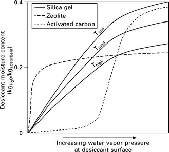
11.6 Qualitative equilibrium isotherms (for illustrative purposes only) for adsorption of water by silica gel, zeolite, and activated carbon. Each isotherm shows, for a given desiccant temperature, the equilibrium adsorbed moisture content as a function of the vapor pressure at the adsorbent surface (this corresponds to the partial pressure of water when the desiccant is in thermal equilibrium with air). Isotherms are shown for three adsorbent temperatures for silica gel, and for clarity only one is shown for zeolite and activated carbon.
The other important aspect to consider when looking at isotherm data for a substance is the temperature dependence of the isotherms. For an example of such a chart, see Fig. 11.13 in Section 11.5.2
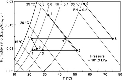
11.8 Representative average air side state points for enhanced desiccant wheel (with sensible exchange wheel and regeneration- side evaporative cooling) in psychrometric chart.
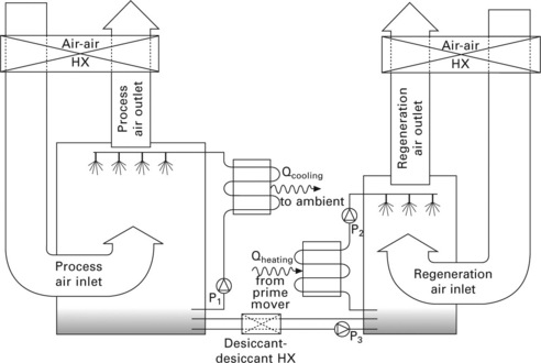
11.9 Schematic of one possible liquid desiccant dehumidification system. Pump P3 flows just enough to maintain fixed solution concentrations in the sumps of the conditioner and regenerator. It is also possible to have cooling coils immersed in the process air stream, with the desiccant spray forming films over them.
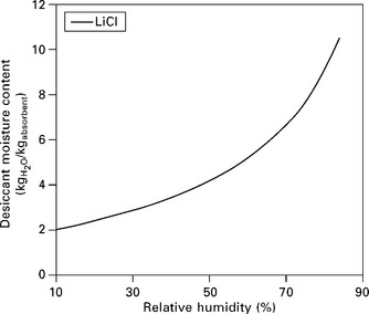
11.10 Equilibrium isotherm for aqueous LiCl. Isotherm will shift up with a decrease in solution temperature (or down with an increase in temperature).
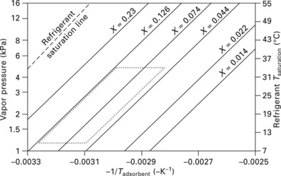
11.13 Dühring diagram for water on silica gel 3A, plotted from state equation given in Ng et al (2001). X denotes the value of kgH2O/kgadsorbent for each isostere (line of constant adsorbent loading). Dotted lines: simple (non-recuperative) adsorption cycle operating with the following conditions: Tdesorption = 80 °C (176 °F, –0.00283 in diagram); Trejection = 32 °C (90 °F, –0.00328 in diagram), corresponding to a pure water vapor pressure of 4.76 kPa; Tevaporation = 10 °C (50 °F), corresponding to a pure water vapor pressure of 1.23 kPa.
The hygroscopic nature of a desiccant means that, when the desiccant is relatively dry, water vapor will spontaneously adsorb onto its surface in an exothermic reaction. In fact, this will occur even at temperatures above the psychrometric dewpoint of the surrounding air (another way of saying this is that the vapor pressure at the desiccant surface is much lower than that over a surface of liquid water at the same temperature). The reversible nature of this reaction is equally important: heating the desiccant can desorb the water off the desiccant surface (a phase change requiring a heat input equal to the heat of sorption). Importantly, the temperature required to regenerate (i.e. dry) many desiccants is well below the boiling point of water, and within reach of the low-temperature waste heat recovery utilized in small- and micro-CHp systems.
Thus, by exposing a desiccant material alternately to a process air stream (i.e. one to be dehumidified) and to a hot exhaust airstream (which is exhausted to the environment), the desiccant can be alternately saturated with moisture and regenerated. This is the basis of the basic solid desiccant process depicted in Figs 11.4 and 11.5
Desiccant wheel configuration options
For solid desiccant systems, a large number of configurations are possible when designing the internal components of a desiccant wheel unit. Every desiccant system has the essential components of a desiccant and a regenerator, and a system could be designed with single or multiple stages of these. In addition, single or multiple heat recovery exchangers (which transfer heat but not moisture), evaporative coolers, and sensible cooling coils or evaporators can be chosen. The number of possible combinations and sequences is enormous, and only a relatively small number have been studied in detail. Starting with the most basic cycle, some configurations that have already been explored and implemented are described below.
Basic cycle
The most basic configuration of a desiccant wheel consists of simply an adsorbent-coated wheel rotating between two air streams, with a sensible cooling coil (or evaporator) to remove the sensible load, as shown in Fig. 11.4. The rotation speed of the wheel is generally low enough (~1 rotation per minute) that the sensible energy transferred from the regeneration airstream to the process airstream is small. However, the water vapor adsorbed onto the desiccant surface in the process stream undergoes a phase change from vapor to an adsorbed quasi-liquid (an adsorbed substance generally has internal energy somewhere between its solid and liquid forms at the given temperature). The release of that latent heat raises the process air temperature, and in practice this sensible heat gain is roughly equal to the latent energy removed from the process stream. In this sense the desiccant wheel is a constant enthalpy device that exchanges latent energy for sensible energy, simultaneously dehumidifying and heating the process airstream.
Even in this most basic configuration, a desiccant wheel can be very helpful. Since the process stream is dehumidified already, the evaporator/cooling coil need only provide sensible cooling. Thus it only has to cool the process air to the desired dry bulb temperature, rather than all the way to the (much cooler) desired dew point temperature, improving the cooling system COP and capacity.
Cycle enhancements
Although heating the process air is undesirable, it does provide valuable opportunities. In fact, often the temperature of the dehumidified air leaving the wheel is so high as to be significantly above ambient temperature, allowing sensible heat exchange with the ambient air through a run-around loop, heat pipe, thermosiphon, or sensible wheel. Additionally, a large efficiency gain can be achieved by utilizing outgoing ventilation air as the heat sink for this sensible exchange, then subsequently heating it for use as the regeneration air stream. This can simultaneously reduce the sensible load remaining for the sensible cooling coil and reduce the regeneration heat required to regenerate the desiccant.
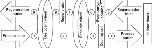
In terms of packaging, a particularly convenient and common configuration is to include a sensible energy exchange wheel in series with the desiccant wheel, as shown schematically in Fig. 11.7 and on a psychrometric chart in Fig. 11.8. This wheel exchanges sensible energy without transferring moisture, preheating the regeneration air before it reaches the heater, and cooling the dehumidified process air before it reaches the conditioned space, cooling coil, evaporator, or air handling unit. This simultaneously reduces the sensible load required of the cooling coil and reduces the amount of heat required for regeneration.
Once a sensible wheel has been added to the system, another possible enhancement is to add evaporative cooling to the regeneration side, before the sensible wheel (as also shown in Fig. 11.7). Although this may adversely affect the regeneration of the desiccant wheel, it also introduces the possibility of cooling the dehumidified process stream down to the wet bulb temperature of the regeneration inlet air. In one configuration, the outgoing ventilation (i.e. building exhaust) air is available for sequential use, first as a heat sink for the heat of adsorption, and next as the regeneration air stream. With this configuration, under the right climatic conditions and with a sufficiently effective sensible wheel, the dehumidified air can even be cooled below the setpoint temperature of the space, completely abdicating the need for any cooling equipment beyond the desiccant wheel itself. In practice, however, the climatic conditions amenable to this scenario are not very common, and even sophisticated desiccant wheel configurations for space cooling of occupied buildings are generally installed with supplementary sensible cooling equipment (such as vapor compression cooling). An absorption or adsorption heat pump could also be used for the supplemental sensible cooling.
Evaporative cooling of the regeneration air, given sequential use of the regeneration air as heat sink and for regeneration, does have an adverse effect on the regeneration process. This adverse effect can be simply expressed in two scenarios: (1) for a fixed amount of heat input to the regenerative heat exchanger, it increases the RH of the regeneration air (and thus diminishes the moisture removal capacity of the wheel), or (2) for a fixed amount of moisture removal, it increases the required heat to the regenerator. Thus, in cases where a desiccant wheel installation has excess moisture removal capacity, evaporative cooling and sequential use of the regeneration air is an attractive option for reducing supplemental HVAC capacity requirements.
In cases where the desiccant wheel does not have excess moisture removal capacity, this adverse effect can be circumvented by using a parallel approach to evaporative cooling/heat sinking and regeneration. In a parallel arrangement, outgoing ventilation air is evaporatively cooled, passes over the sensible wheel, and is exhausted. Meanwhile a separate air stream (perhaps outdoor air) is used for regeneration. This opens additional possibilities for providing total (sensible and latent) cooling with a solid desiccant humidifier without supplementary equipment.
Additional configurations have been explored, including two-stage (parallel) regeneration for improved thermal COP (Kodama et al, 2003); dual desiccant wheels and dual cooling coils, and multiple-stage (serial) regeneration stages for more complete dehumidification (Henning et al, 2007); three- and four- wheel arrangements for high humidity climates (Kodama et al, 2003); and many more.
11.4.2 Liquid (absorptive) desiccant processes
Compared with solid desiccants, liquid desiccants have the advantage of very high specific moisture capacity: in fact, LiCl will absorb 10 times its own mass of water if allowed to reach equilibrium in a 90% RH environment (ASHRAE, 2005). However, the degree to which the absorption process approaches the equilibrium state depends on the amount of surface area exposed to air and the contact time with air. A quiescent liquid/air interface is not sufficient to achieve practical absorption rates. Thus, in order to increase surface area, most liquid desiccant systems either spray the desiccant into an air stream, or pass the air stream through an extended surface contact medium through which a falling film of desiccant falls. In the case of spraying, small droplet sizes clearly have an excellent ratio of surface area to volume, and smaller droplets also fall more slowly, achieving a longer residence time in the air stream. However, any spraying process creates a distribution of droplet sizes, and when the average vertical velocity of the falling droplets is comparable to or slower than the airflow velocity, many smaller droplets will be carried upward with the air stream, requiring additional filtering equipment to prevent them entering the process air stream. This filtering becomes a necessity even for falling film systems, as high local velocities through the media create very small liquid droplets that can be carried with the air stream.
Two more advantages of liquid desiccants are that they can be regenerated with a lower temperature than most solid desiccants (although recently developed zeolites can also achieve low regeneration temperatures), and the liquid desiccant solution can be heated and cooled independently of the process and regeneration air streams (e.g. in liquid-to-liquid heat exchangers). This prevents the heat of regeneration from being dumped into the process air stream, and allows unheated air (ambient or building exhaust air) to be used for regeneration. This is shown in Fig. 11.9. Additionally, separating the desiccant heating and cooling processes presents the opportunity for recuperative heating of the diluted absorbent with the strong absorbent where the solution temperatures overlap.
Liquid desiccant solutions
The most common solution used in liquid desiccant dehumidification is aqueous LiCl, LiBr, CaCl2 and triethylene glycol are possibilities that have been experimented with. A liquid desiccant’s vapor pressure is basically proportional to its temperature and absorbent concentration. An equilibrium isotherm of LiCl is shown in Fig. 11.10.
11.4.3 System integration options
Several choices remain in designing a desiccant wheel or liquid desiccant installation. The desiccant dehumidifier is generally configured to be in series with the unit that provides sensible cooling to the space (a cooling coil, evaporator, or air handling unit). In some cases, however, the desiccant unit can be installed in parallel with and independent of the existing HVAC system. This would make sense for a retrofit where, for example, a sensible heat recovery wheel is incorporated into the desiccant wheel unit.
For a given desiccant dehumidification unit, where the stages of desiccation, regeneration, heat recovery, and evaporative cooling are in place, some decisions remain about how the unit is integrated with the building’s HVAc system:
• Choice of regeneration air stream source: outdoor air, outgoing ventilation (exhaust) air stream, or some combination.
• Choice of process air stream source: outdoor makeup air, recirculated conditioned air, or some combination.
Schinner and Radermacher (1999) have performed detailed modeling of a combined desiccant/absorption system, demonstrating promising potential for such a system. The most efficient arrangement was predicted to be the use of building ventilation exhaust air for desiccant regeneration, and makeup (outdoor) air for the desiccant process air.
11.5 Closed sorption cycles: absorption and adsorption heat pumps
The two kinds of closed sorption cycles are absorption and adsorption heat pump cycles. 3 Absorption refers to the sorption of a solvent into the bulk of a fluid or material, while adsorption refers to the sorption of a solvent onto the surface of a material. Of these, the absorption cycle is very well established (indeed the first form of mechanical ice production was based on an absorption cycle, invented in 1846 by Ferdinand Carré) and today there are many commercialized absorption heat pump products. Adsorption heat pumps also have a very long history, and adsorptive processes have been used extensively in open desiccant dehumidification systems (not to mention separation processes in the chemical and pharmaceutical industries). However, only a few commercial products are available today, and the adsorption heat pump is a technology currently under intense development.
It is instructive to compare heat-driven heat pumps to the basic reverse Rankine (mechanical vapor compression) heat pump cycle, which is overwhelmingly the most widespread heat pump technology today. In the reverse Rankine cycle, a mechanical compressor compresses refrigerant vapor to a high temperature and pressure state, a condenser cools (and therefore condenses) the refrigerant at constant pressure, an expansion valve expands the refrigerant adiabatically, and an evaporator heats (thereby evaporating) the refrigerant at constant pressure back to vapor to complete the cycle. Absorption and adsorption heat pumps differ from the reverse Rankine cycle by replacing the mechanically powered compressor with thermally powered sorption equipment, taking advantage of the temperature dependence of sorption isotherms to achieve a high-pressure refrigerant vapor state. The various types of absorption and adsorption heat pumps are defined and distinguished by the sorption materials and methods they use to transform low-pressure refrigerant vapor into high-pressure vapor.
11.5.1 Absorption heat pumps
The vast majority of absorption heat pumps use either water/LiBr or ammonia/water as their refrigerant/absorbent working pair. The LiBr-based system has a better COP, but to prevent damage to the system by freezing of the water refrigerant, its evaporator temperature cannot go below 0 °C. Moreover, the solubility characteristics of LiBr in water are such that absorber cooling must be performed at relatively low temperature and/or low concentration to avoid crystallization. In contrast, the ammonia/water system is able to achieve the much lower temperatures required for refrigeration and freezing applications, but because of the toxicity of ammonia vapor, these systems must be either large enough to justify the overhead of safety measures (as in the case of large commercial refrigeration), or small enough to circumvent regulations related to the mass of ammonia in the system (as in the case of domestic refrigerators).
Manufacturers associated with absorption systems with cooling capacity under 20 kW (~6 RT) include Broad (China), Yazaki (Japan), ClimateWell (Sweden), Rotartica (Spain), Robur (Italy), and Pink GmbH (Germany).
Fundamentally, absorption heat pumps accomplish the feat of compressing refrigerant vapor with only a very small amount of mechanical input by pumping the refrigerant to high pressure as a liquid rather than compressing it as a vapor.4 The crucial element of the design, then, is how to convert low pressure vapor into a liquid, and high pressure liquid into a vapor. These two tasks are accomplished with heat-powered absorption and desorption.
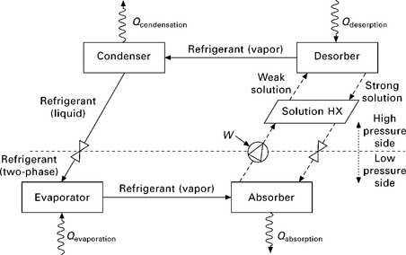
An absorption heat pump is best shown schematically as if superimposed on a Dühring diagram, as shown in Fig. 11.11, where increasing height corresponds to increasing pressure, horizontal distance to temperature, and each diagonal line is a particular absorbent equilibrium concentration. In an absorption heat pump, vapor leaves the evaporator as it is absorbed into strong solution in the absorber. This releases the refrigerant’s latent heat of absorption, so that the absorber must be actively cooled. 5 Eventually, as the absorbent becomes nearly saturated with refrigerant, it is pumped to a high pressure desorber (also called a generator), first being pre-heated in the solution heat exchanger. In the desorber, heat is added to the dilute solution, evaporating the refrigerant, making the solution stronger and driving high pressure refrigerant vapor to the condenser. The remaining strong liquid solution need only be cooled and depressurized to absorb refrigerant vapor again. The solution is pre-cooled in the solution heat exchanger (HX), adiabatically cooled through a throttling valve, and arrives back at the absorber to complete the absorption/desorption cycle. The balance of the system (evaporator, condenser, and expansion valve) operates as in a reverse Rankine (i.e. vapor compression) cycle.
An important efficiency improvement to the absorption cycle is achieved by the generator-absorber heat exchange cycle, commonly known as the GAX cycle. The GAX cycle can be thought of as the logical extension of extending the solution heat exchanger into the desorber (generator) and absorber. The latent heat of absorption which is gained by the absorber is used to provide heat to the desorber, and the latent heat of desorption released by the desorber cools the absorber. In this way, less heat needs to be added to the desorber, and similarly less heat needs to be rejected to the ambient from the absorber. This is only possible if temperatures overlap between the desorber and absorber, generally precluding GAX from water/LiBr systems.
The most important consideration when choosing a cycle type for a cogeneration system is the available waste heat temperature. Since every heat-activated cooling system has a minimum regeneration temperature, and since many small cogeneration systems have a relatively low waste heat temperature, many cooling technologies are impractical for use with small CHP. For example, a micro-CHP device may produce hot water at 80 °C, just hot enough to drive a single-effect absorption chiller but not nearly hot enough for a double- or triple-effect chiller.
For applications with low heat recovery temperature, it may be necessary to utilize a half-effect absorption cycle. The half-effect cycle requires an additional absorber, desorber, solution heat exchanger, and solution pump, and also has a lower COP than the single-effect cycle. However, the required driving temperature is significantly lower.
11.5.2 Adsorption heat pumps
In common with the absorption cycle, the adsorption heat pump replaces the mechanical compressor of the reverse Rankine cycle with sorption equipment. However, adsorption is used instead of absorption, and no solution pump is needed. Compared with absorption heat pumps, adsorption heat pumps are less well developed and generally have a lower thermal COP, but have a wider range of possible working pairs (see Table 11.3), a wider range of regeneration temperatures, and can have lower parasitic power requirements. One major challenge of adsorption heat pumps is packaging the adsorbent to achieve good heat and mass transfer within a reasonable volume and mass.
Manufacturers associated with small adsorption systems include Jiangsu Shuangliang (China) Mayekawa (Japan), and SorTech AG (Germany).
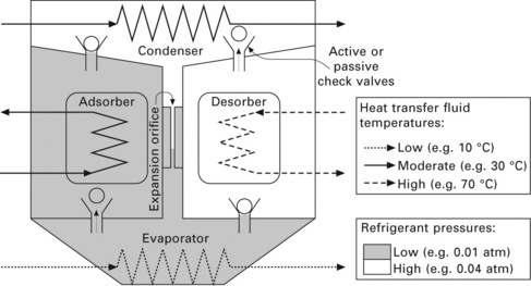
In an adsorption heat pump, shown in Figs 11.12 and 11.13, two adsorbent- coated heat exchangers (or adsorbent beds) are placed in separate sealed chambers. Each coated heat exchanger has piping to allow heating or cooling water to flow within. Thus, by heating one of the heat exchangers (the desorber), refrigerant will be desorbed from its surface, pressurizing its chamber until the upper valve opens, allowing refrigerant vapor to pass to the condenser (which is cooled by ambient-temperature water). The condensed refrigerant drips by gravity to an expansion orifice or valve and adiabatically cools upon expansion. The expansion process generates two-phase refrigerant, with the liquid refrigerant evaporating from the surfaces of the evaporator to provide cooling capacity. The pressure differential across the expansion orifice is maintained by cooling the second coated heat exchanger (the adsorber) with ambient-temperature water, thus causing refrigerant vapor to adsorb onto its coated surface. This arrangement can be maintained until the desorber approaches a ‘dry’ state and the adsorber approaches a saturated state. The adsorber/desorber roles of the two coated heat exchangers are then reversed, allowing the process to continue. Thus the adsorption heat pump is a periodic cooling device - although when operating properly, an excess of liquid refrigerant will build up on the evaporator during the peak sorption period, which buffers the capacity delivered by the evaporator during adsorption/desorption switching periods.
The necessity of periodically heating and cooling the adsorber heat exchangers and associated piping accounts for the generally lower thermal COP of adsorption systems compared with absorption systems, since heating this ‘dead mass’ consumes driving heat (which is then rejected to the ambient in the next adsorption phase) without contributing additional cooling capacity. However, since no solution pump is required for an adsorption heat pump, the potential exists for improving the ECOP compared with absorption systems. Also, the wide variety of adsorbents available and in development, particularly a diversity of zeolites, hold much promise for enabling adsorption heat pumps to efficiently operate under a wide range of conditions, including utilizing much lower heat source temperatures than required by absorption systems.
Refrigerant/adsorbent working pairs that have been used for adsorption heat pumps include water/silica gel, water/zeolite, ammonia/activated carbon, butane/silica gel, methanol/silica gel and others. Since adsorption involves van der Waals bonding, and since hydrogen bonding is the strongest form of van der Waals bonding, the use of small polar molecules such as water, ammonia and methanol as refrigerants tends to result in the best performance.
11.6 Steam ejector cycle
Whereas sorption heat pumps replace the compressor of a VCC with a set of thermally-driven sorption equipment, the ejector cycle replaces the compressor with a boiler, feed pump, and ejector: a mechanically simple device with no moving parts (Fig. 11.14). However, although the ejector cycle (Fig. 11.15) is attractive for its simplicity, it does not achieve as high a performance as sorption heat pumps. Also, currently there are no commercially available cooling products based on the ejector cycle, although there is much ongoing research.
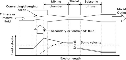
11.14 Schematic of an ejector with fluid velocity profiles. Solid double line: fully mixed fluid; solid single line: primary fluid; dotted line: secondary fluid (figure adapted from Sun, 1999).
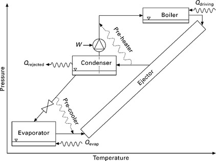
11.15 Ejector cycle schematic, shown with two optional pre-heating and pre-cooling heat exchangers for improved capacity and COP.
The ejector cycle most commonly uses water as a working fluid, although various compounds have been tried (see Sun, 1999). The steam ejector refrigeration cycle was utilized widely during the 1930s, and until recently, very little further development has been pursued. Current areas of research include improving the COP and developing systems that can operate with lower boiler temperatures (to enable waste heat and solar firing).
11.7 Component-specific efficiency and effectiveness metrics
The figures of merit most commonly used for describing the performance of cooling devices are the COP, thermal COP, and the specific cooling power. These metrics are useful for sorption heat pumps and dehumidification systems that provide sensible or total (sensible and latent) cooling. However, some desiccant dehumidification configurations provide latent cooling without sensible cooling, and a distinct approach must be taken to evaluate their effectiveness.
11.7.1 Thermal coefficient of performance (COP) and Carnot COP
The thermal COP is analogous to the more familiar COP used with vapor compression cycle (VCC) heat pumps. However, whereas the VCC COP is the ratio of delivered heat or cooling power to the electrical or mechanical power input, the denominator in the thermal COP is the thermal power input. The advantages of HACTs are obscured by the fact that this important distinction is often overlooked.
It is important to remember the more thermodynamically valuable nature of electricity compared with fuel or heat when comparing VCC COPs to thermal COPs. In this regard, if it is assumed that three units of fuel (i.e. high-temperature heat) are required to produce one unit of electricity, then an electrically-driven heat pump with a COP of 3 will have equivalent source fuel utilization rate to a fuel-fired, heat-activated heat pump with a COP of only 1. In the case of waste-heat-activated cooling technologies, the accounting is even more favorable towards the HACT. For example, imagine that facility ‘A’ utilizes a CCHP system which incorporates a waste-heat-driven HACD with a COP of 0.5, while facility ‘B’ utilizes grid electricity and a VCC heat pump with a COP of 4. Depending on factors such as equipment utilization rate, the assumed conversion efficiency of the electric grid, climate, and many others, facility ‘A’ might turn out to use less source fuel energy than facility ‘B’ to meet the same loads throughout the year (it will likely also eliminate expensive demand charges on its electric bill which are usually incurred during the hottest days of the year). This highlights the need to take a system-wide approach to system performance, rather than simply focusing on the COP values for different cooling technologies. Another perspective on thermal COP is provided by comparing it with the Carnot limit for a given regeneration temperature. This is shown for typical system COPs in Fig. 11.16. System-wide approaches to measuring efficiency are addressed in Section 11.8.
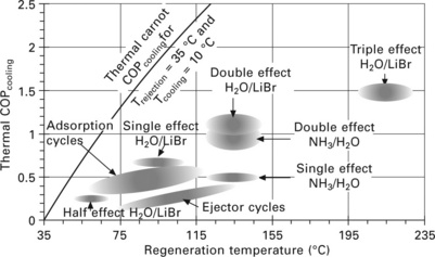
Figure 11.16 shows the typical ranges of firing temperature and COP for absorption, adsorption and ejector cycles. Of the plotted technologies, four are commercially available: (1,2) single-effect H2O/LiBr or NH4/H2O machines, (3) double-effect H2O/LiBr machines, and (4) adsorption machines with various working pairs. The various working pairs for adsorption machines are discussed in Section 11.5.2. Although the potential exists for large COP improvements with multi-stage adsorption machines (see Douss and Meunier, 1989), this possibility is left out of the figure since experimental results for such a machine are not well established.
An interesting note to Fig. 11.16 is that the COP range for a given absorption technology is flat - the COP for single-effect H2O/LiBr absorption, for example, does not increase with increasing firing temperature. This is a consequence of the working fluid properties. If a higher heat source temperature is available, utilizing a double-effect system does increase COP, but the COP for double-effect is also flat. This dependence of performance on working fluid pair (and not heat source temperature) is in fact a general characteristic of sorption heat pumps. The region in Fig. 11.16 for adsorption cycles displays a diagonal tilt because it represents a family of working pairs. Although not sorption-based, the ejector cycle region also represents a family of working fluids and geometries.
The Carnot COP of a VCC heat pump is the best possible performance achievable between two source/sink temperatures, given a mechanical or electrical input. It is derived in every thermodynamics fundamentals textbook. The Carnot thermal COP of a HACD is derived in Herold et al (1996) by coupling a Carnot power production cycle to a Carnot heat pump cooling cycle. It is assumed that (1) the work produced by the power cycle equals the work consumed by the cooling cycle, and (2) the heat rejection temperature of the power cycle equals the heat rejection temperature of the cooling cycle. There are thus three temperatures involved in calculating the Carnot thermal COP for cooling: the low temperature (i.e. evaporator) heat source (T0), the heat rejection temperature (T1), and the high temperature heat source (T2). The resulting expression is given in Equation 11.1, where the first quotient is the Carnot efficiency for a power cycle and the second is the Carnot COP for a cooling cycle:
This efficiency limit can equivalently be applied to an engine-driven VCC device or to a directly heat-activated cooling device. Thus, considering the various energy conversion and transmission losses incurred by centrally generating power and distributing it to utility customers’ VCC systems, it is not surprising that a directly-fired HACD should be able to demonstrate source-energy efficiency comparable to or better than conventional VCC systems. Of course, this is especially the case when the HACD is driven by low-grade heat that is rejected from an on-site power cycle or collected by a solar collector.
Although not discussed in detail in this chapter, it is important to note that most cooling devices are also capable of running in a heating mode during the heating season. The Carnot thermal COP for heating mode is given by Equation 11.2.
The fact that the heating COP (even for a system far from the Carnot ideal) is always greater than 1 means that the installation of a heat-activated heat pump can provide benefits both during the heating and cooling seasons. For heating use, the evaporator would be heated by the ambient, and the heat rejected by the condenser and adsorber would be used for space heating. For example, with a heating thermal COP of 1.5, an adsorption machine could provide 1.5 kW of space heating at 35 °C (95 °F) for every kW of heat produced at higher temperature by the prime mover.
The thermal COP of heat-activated machines can generally be expressed as a simple ratio of useful thermal output to the thermal input, as in Equation 11.3, but can also include the parasitic loads (e.g. electricity to run pump and fan motors) required by the device. Further, there are at least two ways of accounting for parasitic loads: as subtracted from the cooling energy (Equation 11.4) or added to the regeneration energy (Equation 11.5).
In any equation accounting for parasitic loads, the parasitic could also be weighted by the electric conversion efficiency, giving the amount of fuel that must be burned to supply the parasitic load. Taking this approach, Equation 11.6 could be substituted into Equation 11.4 or 11.5 above to replace the parasitic term to achieve an energy efficiency accounting using only thermal terms:
The performance of a heat-activated cooling device can also be expressed as the electric COP, or ECOP, which neglects thermal inputs and is the cooling output divided by the electrical parasitics, as shown in Equation 11.7. This definition makes sense if the heat driving the system is assumed to be truly free, and it demonstrates the reduction in electricity consumption of a HACD compared with a VCC. That the ECOP of a HACD exceeds the COP of a VCC is a necessary (but not necessarily sufficient) condition for demonstrating improved energy efficiency of the HACD. In practice, the electrical parasitics involved in running an absorption chiller are not insignificant, but the ECOP of an absorption system still easily surpasses the COP of a VCC. The ECOP of an adsorption chiller is generally even more favorable since pressurization of the working fluid is accomplished thermally rather than mechanically. There is no theoretical limit to the ECOP; indeed HACD have been built that require no electricity at all.
Thus, there are at least six possibilities for how to calculate the efficiency of a heat-activated sensible or total cooling device on a First Law basis. Further, when the choice of lower heating value vs. higher heating value is considered for the efficiency term in Equation 11.6, there are at least eight calculation possibilities (and the continuous range of numerical values that can be used for that efficiency term means the possibilities are infinite). Additionally, any thermal COP value can be divided by the Carnot thermal COP value to obtain a Second Law efficiency (which is always between 0 and 1).
No definition is inherently better than another. Clearly, however, one must be careful in assessing efficiency claims, and should clearly state assumptions when reporting efficiencies, as a manipulative or careless choice of efficiency definition can have misleading results.
11.7.2 Desiccant dehumidification effectiveness
Defining the effectiveness of a desiccant dehumidification process is complicated by the fact that a desiccant wheel can be useful without actually providing any reduction in the energy content (enthalpy) of the process air. For example, as noted in Section 11.4, the process air exiting a desiccant-coated wheel experiences essentially no change in enthalpy, as it is sensibly heated to the same degree it is latently cooled. Thus, for the most basic desiccant wheel configuration (Figs 11.7 and 11.8), if any one of Equations 11.3-11.5 were applied, the cooling provided would be zero! Thus these definitions are clearly not helpful for the basic configuration.
Since the primary objective of dehumidification is moisture removal, Equation 11.8 makes intuitive sense, and is commonly used. Parasitic energy consumption could be subtracted from the latent heat removal term, or added to the regeneration term, following the pattern of Equations 11.4-11.6. However, as the primary ‘parasitic’ effect of a desiccant wheel may be an increase in pressure drop that must be overcome by the ventilation fan, or perhaps an increase in air flow rate, defining the parasitic load may not be straightforward. Another possibility is to define the dehumidification effectiveness relative to the ideal of removing all moisture from the process air (Equation 11.9). However, drier is not always better if an ideal humidity level has been reached, and this definition does not provide fair comparisons among different ambient conditions.
The effectiveness definitions for dehumidification in Equations 11.8 and 11.9 can be useful for comparing one dehumidifying device to another under similar conditions, where dehumidification is the only objective. However, cycle enhancements to remove sensible load, such as adding a sensible wheel to a desiccant wheel system, will be under-appreciated by these definitions. For a desiccant dehumidification configuration that provides total cooling, Equations 11.3-11.5, or a system-wide performance metric, would be more appropriate.
11.8 System-wide performance and efficiency metrics
Attempting to define and interpret the component-specific efficiencies for each component in a CCHP system can be difficult, and sometimes the fuel consumption to meet a given set of loads can be improved by sacrificing one component’s individual performance to benefit another’s (e.g., in a combined cycle power plant, the Brayton topping cycle’s exhaust gas temperature and pressure are increased to benefit the Rankine bottoming cycle and improve the plant’s overall thermal efficiency). Thus, in many cases it makes more sense to calculate the system-wide performance, capturing the interactions and synergies among components into a single metric which can be compared with alternative integrated systems.
11.8.1 Energy content of fuel
There are basically two alternatives to account for the fuel input to a system: the lower heating value (LHV) basis or the higher heating value (HHV) basis. Each alternative is commonly used, and the choice is fairly arbitrary since results in either basis are readily interconverted. However, arbitrariness does not mean unimportance; indeed the choice of heat value should always be stated when reporting any performance metric that involves the fuel energy, such as system efficiency. Unfortunately, this choice is often not specified when efficiency values are reported, leading to much confusion and difficulty in comparing systems.
Both heating value definitions include all the sensible energy removed from an exhaust stream by cooling it to 25 °C (77 °F). However, the LHV assumes that all water vapor formed by combustion remains vapor, while the HHV assumes that all water vapor condenses. HHV is typically 7% to 11% higher than LHV for hydrocarbon fuels.
Consider the energy accounting consequences for the CHP system shown in Fig. 11.1 if the fuel basis is changed from HHV to LHV. The electrical and hot water energy flows (i.e. kW or Btu/hr) out of the system will clearly not be altered by this change in fuel accounting, so their efficiencies will be increased by an amount inversely proportional to the decrease in fuel energy (e.g. from 18% HHV electrical efficiency to 20% LHV electrical efficiency, corresponding to a 10% lower LHV energy content than HHV energy content). On the other hand, in order to arrive at a proper First Law energy balance on the system, the exhaust flow needs to be evaluated with respect to a reference state, and this reference state must correspond to the reference state used in the fuel heating value definition. For a prime mover with a sufficiently effective exhaust gas heat exchanger and a relatively low heat recovery temperature, it is possible to cool the exhaust gas below its dew point (about 60 °C/140 °F for stoichiometric combustion of natural gas in air), thereby transferring latent heat from the exhaust to the heat recovery fluid. Thus the use of the LHV reference state can allow the exhaust mass flow out of the system to be considered a heat flow into the system, making possible an overall fuel utilization rate greater than 1.
11.8.2 System-wide metrics
The most commonly used system-wide performance metric is the fuel utilization factor shown in Equation 11.10.6 This is a simple First Law accounting of the useful energy flows (regardless of temperature or type) obtained from the system, divided by the fuel input. While straightforward to calculate and understand, it does not account for the thermodynamic or economic value of any outputs.
An accounting of the energy flows based on the Second Law of Thermodynamics is shown in Equation 11.11, where the heating and cooling flows are weighted by the theoretical efficiency of a Carnot heat pump operating between the relevant source and sink temperatures (i.e. the second quotient of Equation 11.1), and electrical power and fuel are equivalent to their First Law values. Although this definition is derived directly from thermodynamics, is does not always correspond with the realities of economics, or with the actual efficiencies of alternative heating and cooling methods.
In the US, the 1978 PURPA regulations define a combined efficiency for qualifying cogeneration facilities, given in Equation 11.12. The factor of 2 in this definition has no direct thermodynamic justification, and the resulting efficiency value will generally fall between the values calculated by the FUF and the Second Law efficiency.
The fuel utilization efficiency shown in Equation 11.13 is a practical definition for comparing different systems. 7 It weights each energy flow by how it would be produced by an alternative conventional device. Importantly, this means that all four terms in Equation 11.13 (i.e. work, fuel, heating, and cooling) are converted to units of energy of comparable value, making it more thermodynamically justifiable than Equation 11.10 from an exergetic standpoint. It is, however, up to the discretion of the user to choose baseline system efficiencies, making it less thermodynamically rigorous than Equation 11.11. Also note that Equation 11.13 is not directly bounded by the First Law, and can exceed 1.
The calculation is straightforward when assuming baseline devices that are fuel-fired (such as a furnace, where hheater - 0.8 (LHV) would be a reasonable choice). However, if a VCC device is chosen as a baseline system, then the overall fuel utilization of that device (rather than its COP) must be considered, which also requires an assumption be made for electric grid efficiency. For example, if the baseline cooling device is chosen to be a VCC air conditioner, an appropriate choice for hAC, assuming an air conditioner with COP of 3 and a grid efficiency of 1/3 (LHV), would be ηheater = (3) (1/3) = 1 (LHV). Of course a similar procedure applies to calculating ηheater for an electrically-driven space-heating heat pump.
The fuel chargeable to power (FCP) is based on the premise that the CHP system heat output displaces the use of a boiler, with electricity being produced as a byproduct. Under this premise, it makes sense to calculate an electrical efficiency where the fuel that would have fired a boiler is subtracted from the fuel the CHP system consumed. This can be generalized to include cooling outputs, as in Equation 11.14.
In common usage, the FCP ignores cooling and is often expressed as a heat rate (i.e. a ratio of inputs to outputs). In Equation 11.15 it is generalized to include cooling and expressed as the FCP efficiency, a ratio of inputs to outputs (the inverse of the FCP heat rate).
The FCP efficiency metric (Equation 11.15) is very similar to the fuel utilization efficiency (Equation 11.13), except that the fuel chargeable to heating and cooling is subtracted from the inputs rather than credited to the outputs. A comparison of these two metrics is shown in Fig. 11.17. There are three pairs of lines in Fig. 11.17. Each pair compares the fuel utilization efficiency with the FCP efficiency, and each pair uses a different independent variable while holding others constant. The pair with crosses varies the electrical efficiency while holding fixed the heating and cooling efficiencies; the pair with squares varies the heating efficiency while fixing the electrical and cooling efficiencies; and the pair with pluses varies the cooling efficiency while fixing the electrical and heating efficiencies. A similar exercise can be carried out for the several other efficiency definitions given in this section, and each definition will exhibit distinct values and trends. This reinforces the importance of a critical approach to evaluating and reporting efficiency values.
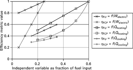
11.17 Comparison of fuel utilization rate (Equation 11.13) and fuelchargeable to power efficiency (Equation 11.15), assuming η heater, fuel– basis = 0.8 and η AC,fuel–basis = 1.05. Solid lines: fuel utilization efficiency. Dotted lines: FCP efficiency. Crosses: as functions of electrical output of system, holding fixed, as fractions of fuel input, Qheating = 0.6 and Qcooling = 0; squares: as function of Qheating holding fixed Welectric = 0.25 and Qcooling = 0; pluses: as function of Qcooling holding fixed Welectric = 0.25 and Qheating = 0.
11.8.3 Comparative performance relative to baseline systems
Comparing to baseline systems is a more empirical approach, of a less thermodynamically fundamental nature than metrics such as the COP. It can often be more useful when a direct comparison to conventional systems is desired. However, any comparative performance estimate can easily have a wide span of outcomes, depending on the choice of baseline system, the assumptions made about the baseline system, and the way that various energy flows are accounted for.
One choice for comparing a proposed CCHP system to a baseline one is to use a metric such as the fuel utilization efficiency (Equation 11.13), and the other is to build models of the proposed system and the baseline system to evaluate the relative performance by detailed system simulation. A simple example of this approach is shown in Figs 11.18-11.20, in which the fuel required to meet one unit of loads in a residence is calculated for three systems. For all cases it is assumed that there is a 4:1 ratio of cooling to DHW loads. The height of each box is proportional to the energy it represents.
11.18 Zero-order model of baseline non-CHP system with VCC cooling device and fuel-fired water heater with efficiency of 80%. The conversion efficiency of fuel to electricity is chosen to be typical for a Rankine-cycle-dominated electric grid. Net fuel consumption: 1.01 units per unit loads.
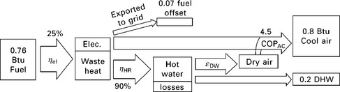
11.19 Zero-order model of CCHP system with desiccant wheel and VCC. The desiccant wheel is assumed to boost the heat pump COP from 3 to 4.5 by separating sensible and latent cooling, and to provide 20% of the driving heat as sensible cooling via an advanced configuration such as that shown in Fig. 11.7. Excess electricity produced offsets production by the grid, assumed to have an efficiency of 35%. Net fuel consumption: 0.69 units per unit loads.
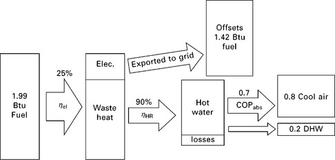
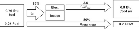
11.20 Zero-order model of CCHP system with absorption chiller. Electricity produced offsets production by the grid, assumed to have an efficiency of 35%. Net fuel consumption: 0.57 units per unit loads.
Figure 11.18 shows a zero-order model (i.e. components are described by fixed values without any independent variables) of a baseline system consisting of a grid-electricity-powered VCC and a fuel-fired hot water heater. The baseline system requires 1.01 units of fuel (0.76 off-site and 0.25 on-site) for every unit of loads. A simple zero-order model of a CCHP system with desiccant cooling is shown in Fig. 11.19. This system requires 0.76 units of fuel on-site for every unit of load, but also is a net producer of electricity. When credit is issued for this production (assuming it offsets grid electricity that would have been produced with an efficiency of 35%), it requires only 0.69 net units of fuel. A zero-order model of a CCHP system with absorption cooling is shown schematically in Fig. 11.20. This system requires more on-site fuel consumption, but also produces a significant excess of electricity. When credit is issued for this electricity, it only consumes 0.57 net units of fuel for each unit of load.
This simple example demonstrates the potential for fuel savings with CCHP systems, and demonstrates the basic methodology of using system modeling to compare system alternatives. Costs can easily be assigned to components and to imported and exported energy to make economic as well as energetic performance comparisons.
11.9 Advantages and limitations of heat-activated cooling
Heat-activated cooling and small-scale CHP systems have a synergistic combination. Without available waste heat, heat-activated cooling technologies must be direct-fired, and in that case they struggle to compete with conventional cooling methods, both on a cost and an energy basis. small-scale CHP without any heat-activated cooling device, often struggles to demonstrate sufficient operating hours throughout the year to justify the capital expenditure on CHP equipment, and may demonstrate only marginally improved energy efficiency compared with state-of-the-art standard energy solutions. However, combining small-scale CHP with HACT can increase both system operating hours and system fuel efficiency. Thus, integration with CHP can justify the energetic and cost performance of HACT, and vice versa. The integrated system performs better than the sum of its parts.
On the other hand, heat-activated cooling for small-scale CHP does suffer some limitations. Most importantly, adding more components to a CHP system increases the initial capital cost, in a technology where high initial cost is a fundamental challenge. secondly, system complexity is also increased, and many heat-activated cooling technologies do not yet have commercial products that are well proven in terms of reliability and longterm performance.
11.10 Future trends
With the proliferation of small-scale CHP installations and an increased emphasis globally on fuel efficiency, small-scale heat-activated cooling technologies have a promising long-term outlook. Although current CHp manufacturers for domestic and commercial CHP applications will probably first succeed in the climate zones most amenable to CHP (i.e. climates with long, heating-dominated seasons), manufacturers will be looking for ways to expand to other regions. As costs for both CHP systems and HACT come down, and as the efficiency benefits are more fully appreciated, HACT can help justify the economics of installation to a much wider set of markets, including residences in cooling-dominated climate regions, commercial establishments with large latent HVAC loads, and industrial applications with large cooling loads.
In general, the capacity of a HACD increases with higher regeneration temperature; while a CHP prime mover has a higher overall efficiency with a lower heat recovery temperature, which extracts the most possible energy from the exhaust and minimizes convective and radiative losses. This fundamental compromise requires technological advances that enable high thermal COPs with lower regeneration temperatures (e.g. advanced desiccant polymers for desiccant wheels and advanced regenerative adsorption heat pumps).
As energy efficiency requirements for HVAC equipment continue to become more stringent, manufacturers are exploiting various technologies proven to improve efficiency, and most of these interact positively with HACT. For example, a VCC system set up for separate sensible and latent cooling can be supplemented with a desiccant dehumidifier. Utilization of low temperature difference (ΔT) heat exchangers enhances the incentive to keep air conditioning evaporator temperatures high, and thus it becomes even more important to perform dehumidification separately from sensible cooling. Higher standards of thermal comfort will incentivize systems that operate efficiently at part load, since they may have to be sized larger to meet higher design-day requirements, and in this area absorption chillers excel. A combination of higher thermal comfort standards and tighter building envelope will increase ventilation requirements, which in turn enhances the benefits of dedicated dehumidification equipment. Further, a CCHP system such as a liquid dessicant/absorption system with on-site power generation can abdicate the need for vapor compression systems altogether, greatly reducing peak electricity demand and reducing fuel consumption. Finally, fuel-flexible external combustion engines and waste-heat or direct-fired HACT can provide a hedge against uncertainty of any one fuel source.
Many HACT have proven to be more efficient solutions to cooling. The four primary barriers to widespread adoption are first cost, system complexity, inherent efficiency limits, and parasitic power consumption.
1. The generally higher first cost of HACT is the most important barrier to more widespread adoption. The fundamental solutions to this are a major shift in energy prices, which would more dramatically reward energy efficiency over first cost, and economies of scale as more units are made, lowering first cost.
2. Complexity of HACT is often cited as a development barrier, but this issue amounts merely to an engineering challenge which can be overcome given sufficient incentive to commercialize a product.
3. A more fundamental issue with HACT is the limits set by Carnot efficiency - but as this chapter has demonstrated, this is primarily an apparent shortfall, resulting from the erroneous direct comparison of thermal COP and mechanical/electrical COP. Furthermore, when fuel is used sequentially, first in a prime mover or process requiring high temperature, and next in a HACD (or when low-temperature solar heat is used), then the use of HACT can boost the overall fuel efficiency well above what is achievable by conventional systems.
4. A final issue with HACT is parasitic power consumption, which tends to increase as pumps and heat exchangers are added to a HACD to improve the thermal COP. If parasitic power consumption is not smartly managed in the design phase, the electrical consumption of a HACD can end up being comparable to the conventional system it replaces - but this potential pitfall can be overcome by good design.
Thus, many of the HACT discussed in this chapter are ready for deployment today, and many more could quickly become widespread given appropriate changes in energy priorities.
11.11 Sources of further information and advice
11.11.1 General - trigeneration
Wu and Wang (2006) provide an overview of CCHP technologies for micro- up to large-scale systems. The European union-funded PolySMART project (Polygeneration with advanced Small and Medium scale thermally driven Air-conditioning and Refrigeration Technology) has many publications available at www.polysmart.org. Neil Petchers’ Combined Heating, Cooling & Power Handbook (2003) contains two chapters (within Section VII) on absorption cooling and desiccant dehumidification (including solid desiccant beds) and how they are relevant to CHP. Review articles on solar cooling are also relevant due to the interest in low-temperature regeneration shared by solar and small-scale CCHP applications - see Hwang et al (2008), Kim and Infante Ferreira (2008), and Anyanwu (2003, 2004). Onovwiona and Ugursal (2006) provide an overview of residential CHP prime movers.
11.11.2 General - heat-activated cooling devices
The IEA Heat Pump program Annex 34, ‘Thermally Driven Heat Pumps for Heating and Cooling,’ is scheduled to be completed in 2011 (www.annex34.org). A US Department of Energy-funded report covers thermally activated technologies: see TIAX (2004). Also, the IEA Solar Heating and Cooling Program Task 25, ‘Solar-Assisted Air-Conditioning of Buildings’ dealt largely with low regeneration temperature heat-activated devices, and was completed in 2004-see Henning (2007) and www.iea-shc.org/task25. pons et al (1999) provide a comparative compilation of the performances of various sorption systems for heating, cooling, and refrigeration applications. The International Sorption Heat Pump Conference, originally dedicated to absorption machines, has been expanded to encompass all sorption cooling and dehumidification processes, as well as cogeneration and fundamentals of heat and mass transfer. It is held in various countries approximately every three years since 1982, including Seoul, Korea in 2008 and Padua, Italy in 2011. Many compilations of these conference proceedings are available, including Radermacher et al (1994), Nikanpour and Hosatte (1996), and Schweigler et al (1999).
11.11.3 Desiccant dehumidification
Munters Corporation produces desiccant-based dehumidification products for industrial, commercial, and residential applications. Brundrett’s Handbook of Dehumidification Technology (1987) provides an overview of traditional desiccant and other dehumidification processes, although specific information on low regeneration temperature processes is hard to find. For information on enhanced desiccant processes, including those that handle sensible load, recent academic literature is the best source (see bibliography for starting points). Also the ASHRAE Handbook: Systems (2008, Chapter 23) contains a helpful overview of desiccant dehumidification.
11.11.4 Absorption heat pumps
Absorption Chillers and Heat Pumps by Herold et al (1996) covers the theory and operation of absorption devices. The ASHRAE Handbook: Refrigeration (2006, Chapter 41) contains an overview of absorption chillers, and the ASHRAE Handbook: Fundamentals (2005, Chapter 22) deals with the basics of sorption fundamentals. The IEA Heat Pump Program Annex 24, ‘Absorption Machines for Heating and Cooling in Future Energy Systems’ was completed in 1999-see www.heatpumpcentre.org - and among their publications is a list of absorption equipment manufacturers. Proceedings from the International Sorption Heat Pump Conference (held every three years) along with articles in the academic literature - particularly in the International Journal of Refrigeration (published by the International Institute of Refrigeration) - provide additional resources.
11.11.5 Adsorption heat pumps
There is not a comprehensive reference for adsorption heat pumps, and perhaps the most helpful way to discover more about them is to take a combined approach: for adsorption fundamentals (which are well established owing to their importance in chemical processing), several helpful books are available; and for heat pump application-specific information, more recent review articles in the academic literature provide information.
Coverage of adsorption fundamentals can be found in Ruthven’s Principles of Adsorption and Adsorption Processes (1984) and R.T. Yang’s Adsorbents: Fundamentals and Applications (2003). Naturally these volumes do not contain information on the most recent advances in adsorbents (nor do they directly address HACT), but nevertheless have excellent and clear discussions of the classifications of adsorbents, their thermodynamics, equilibrium models, and kinetics. Basmadjian’s Little Adsorption Book: A Practical Guide for Engineers and Scientists (1997) provides a more succinct overview of the fundamentals.
With respect to recent advances, Sumathy et al (2003), Lambert and Jones (2005) and Demir et al (2008) provide excellent reviews of adsorption heat pump working pairs and cycle enhancements, and also provide useful comparisons to other heat-activated cooling technologies. Power partners, Inc. is currently manufacturing water/silica gel units in North America of 30 tons and larger (Power Partners, Inc., 2010). Finally, Yong and Wang (2007) review over 100 patents related to adsorption heat pumps, most issued since 2000.
11.11.6 Ejector refrigeration cycle
Well-established ejector performance studies for boiler temperatures of 120-140 °C are readily available; see Chunnanond and Aphornratana (2004a). For low firing temperature ejector cycles, see Sun (1999), Godefroy et al (2007), Chunnanond and Aphornratana (2004b), Yapici and Ersoy (2005) Yapici and Yeti§en (2007), and Meyer et al (2009).
11.11.7 Performance metrics
petrov et al (2004) provide an excellent discussion of efficiency metrics in the context of CCHP systems with case study examples. Carnot COPs and efficiencies of various heat-activated devices are derived in Herold et al (1996). Tozer and James (1997) derive performance limits for multiple effect machines, and Meunier et al (1997) discuss the theoretical performance limits for adsorption heat pumps. For desiccant wheels, Mandegari and Pahlavanzadeh (2009) discuss conventional metrics and propose new ones.
11.14 Appendix 1: Nomenclature and abbreviations
CCHP – combined cooling, heating and power
CHP – combined heating and power
COP – coefficient of performance
FCP – fuel chargeable to power
GAX – generator-absorber exchange
HACT – heat-activated cooling technology
HACD – heat–activated cooling device
HHV – higher heating value of a fuel
HVAC – heating, ventilation and air conditioning
ICE – internal combustion engine
IEA – International Energy Agency, founded 1974 by the OECD LHV – lower heating value of a fuel ORC – organic Rankine cycle MT – microturbine
PEMFC – proton exchange membrane fuel cell
PM – prime mover, the primary fuel conversion device in a CHP system
PURPA – Public Utilities Regulatory Policies Act of 1978
RT – refrigeration ton, equivalent to 3517 W or 12 000 Btu/hr of cooling capacity
SEER – seasonal energy efficiency ratio
T – temperature (°C) or (°F) or (K) or (R)
W – work, usually electrical energy or power (kW)
ε – effectiveness (dimensionless)
11.15 Appendix 2: Notes on terminology
‘Trigeneration’ and ‘combined cooling, heating and power (CCHP)’ are used interchangeably in this chapter. Additional equivalent terms in use include ‘combined heating, cooling and power (CHCP)’ and ‘cooling, heating and power (CHP)’ (in this chapter CHP is used to mean combined heat and power, exclusive of cooling). More comprehensive terms in use include polygeneration and integrated energy systems (IES).
‘Heat-activated cooling technology/technologies (HACT)’ and ‘heat- activated cooling device(s) (HACD)’ are used interchangeably, as appropriate, in this chapter. Additional equivalent terms in use include ‘heat-driven’, ‘thermally-activated’, and ‘thermally-driven’, combined with either ‘cooling’, ‘refrigeration’, ‘chillers’, and/or ‘technology/device’, giving rise to an abundance of equivalent potential abbreviations such as TAT, TAC, TDC, etc
11.12 References
American Society of Heating Refrigeration and Air Conditioning Engineers (ASHRAE). ASHRAE Handbook: Fundamentals 2005;
American Society of Heating Refrigeration and Air Conditioning Engineers (ASHRAE). ASHRAE Handbook: Refrigeration 2006;
American Society of Heating Refrigeration and Air Conditioning Engineers (ASHRAE). ASHRAE Handbook: Systems 2008;
Anyanwu, E.E. Review of solid adsorption solar refrigerator I: an overview of the refrigeration cycle. Energy Conversion and Management. 2003; 44(2):301–312.
Anyanwu, E.E. Review of solid adsorption solar refrigeration II: an overview of the principles and theory. Energy Conversion and Management. 2004; 45(7–8):1279–1295.
Basmadjian, D. The little adsorption book: a practical guide for engineers and scientists. Boca Raton, FL: CRC Press; 1997.
Brundrett, G.W. Handbook of dehumidification technology. London: Butterworths; 1987.
Chunnanond, K., Aphornratana, S. An experimental investigation of a steam ejector refrigerator: the analysis of the pressure profile along the ejector. Applied Thermal Engineering. 2004; 24(2–3):311–322.
Chunnanond, K., Aphornratana, S. Ejectors: applications in refrigeration technology. Renewable and Sustainable Energy Reviews. 2004; 8(2):129–155.
Demir, H., Mobedi, M., Ülkü, S. A review on adsorption heat pump: problems and solutions. Renewable and Sustainable Energy Reviews. 2008; 12(9):2381–2403.
Douss, N., Meunier, F. Experimental study of cascading adsorption cycles. Chemical Engineering Science. 1989; 44(2):225–235.
Godefroy, J., Boukhanouf, R., Riffat, S. Design, testing and mathematical modelling of a small-scale CHP and cooling system (small CHP-ejector trigeneration). Applied Thermal Engineering. 2007; 27(1):68–77.
Henning H.-M., ed. Solar-assisted air-conditioning in buildings: a handbook for planners, 2nd rev. edn. London: Springer, 2007.
Henning, H.-M., Pagano, T., Mola, S., Wiemken, E. Micro tri-generation system for indoor air conditioning in the Mediterranean climate. Applied Thermal Engineering. 2007; 27:2188–2194.
Herold, K.E., Radermacher, R., Klein, S.A.Absorption Chillers and Heat Pumps. Boca Raton, FL: CRC press, 1996.
Hwang, Y., Radermacher, R., Al Alili, A., Kubo, I. Review of solar cooling technologies. HVAC & R Research. 2008; 14:507–528.
Kim, D.S., Infante Ferreira, C.A. Solar refrigeration options - a state-of- the-art review. International Journal of Refrigeration. 2008; 31(1):3–15.
Kodama, A., Hirose, T., Okano, H. translated by. Saha, B., Akisawa, A., Koyama, S., eds. Low-temperature heat driven adsorptive desiccant cooling improved for the use in humid weather. 2003 [Fukuoka, Japan].
Lambert, M.A., Jones, B.J. Review of regenerative adsorption heat pumps. Journal of Thermophysics and Heat Transfer. 2005; 19(4):471–485.
Mandegari, M.A., Pahlavanzadeh, H. Introduction of a new definition for effectiveness of desiccant wheels. Energy. 2009; 34:797–803.
Meunier, F., poyelle, F., LeVan, M.D. Second-law analysis of adsorptive refrigeration cycles: the role of thermal coupling entropy production. Applied Thermal Engineering. 1997; 17(1):43–55.
Meyer, A.J., Harms, T.M., Dobson, R.T. Steam jet ejector cooling powered by waste or solar heat. Renewable Energy. 2009; 34(1):297–306.
Ng, K.C., Chua, H.T., Chung, C.Y., Loke, C.H., Kashiwagi, T., Akisawa, A., Saha, B.B. Experimental investigation of the silica gel-water adsorption isotherm characteristics. Applied Thermal Engineering. 2001; 21(16):1631–1642.
Nikanpour, D., Hosatte, S. September 17–20, 1996, Quebec: cANMET- EDRL. conference proceedings: International Absorption Heat Pump conference. Natural Resources Canada, Montreal, Canada, 1996.
Onovwiona, H.I., Ugursal, V.I. Residential cogeneration systems: review of the current technology. Renewable and Sustainable Energy Reviews. 2006; 10(5):389–431.
Petchers, N. Combined heating, cooling & power handbook: technologies & applications: an integrated approach to energy resource optimization. Lilburn, GA: Fairmont press; 2003.
Petrov, A.Y., Zaltash, A., Labinov, S.D., Rizy, D.T., Liao, X., Radermacher, R. Evaluation of different efficiency concepts of an integrated energy system (IES). Anaheim, CA: American Society of Mechanical Engineers. 347–356, 2004.
Pons, M., Meunier, F., Cacciola, G., Critoph, R.E., Groll, M., Puigjaner, L., Spinner, B., Ziegler, F. Thermodynamic based comparison of sorption systems for cooling and heat pumping. International Journal of Refrigeration. 1999; 22(1):5–17.
[online], available at: Power Partners, Inc (accessed June 2010). Eco-Max Adsorption Chillers 2010. http://www.eco-maxchillers.com/
Radermacher, R., Herold, K., Miller, W., Perez-Blanco, H., Ryan, W., Vleit, G. translated by New Orleans, Louisiana: American Society of Mechanical Engineers. Proceedings of the International Absorption Heat Pump Conference 1994; viii:534.
Ruthven, D.M. Principles of adsorption and adsorption processes. New York: Wiley; 1984.
Schinner, E.N., Jr., Radermacher, R. Performance analysis of a combined desiccant/absorption air-conditioning system. HVAC and R Research. 1999; 5:77–84.
Schweigler C., Summerer S., Hellman H.-M., Ziegler F., eds. Proceedings of the International Sorption Heat Pump Conference, March 24-26, 1999, Munich. Germany: Lang Offsetdruck GmbH, 1999.
Sumathy, K., Yeung, K.H., Yong, L. Technology development in the solar adsorption refrigeration systems. Progress in Energy and Combustion Science. 2003; 29(4):301–327.
Sun, D.-W. Comparative study of the performance of an ejector refrigeration cycle operating with various refrigerants. Energy Conversion and Management. 1999; 40(8):873–884.
TIAX, Review of Thermally Activated Technologies TIAX LLC. A Distributed Energy Program Report for the US DOE Office of Energy Efficiency and Renewable Energy 2004;
Tozer, R.M., James, R.W. Fundamental thermodynamics of ideal absorption cycles. International Journal of Refrigeration. 1997; 20(2):120–135.
Wu, D.W., Wang, R.Z. Combined cooling, heating and power: a review. Progress in Energy and Combustion Science. 2006; 32(5–6):459–495.
Yang, R.T. Adsorbents: fundamentals and applications. Hoboken, NJ: Wiley- Interscience; 2003.
Yapici, R., Ersoy, H.K. Performance characteristics of the ejector refrigeration system based on the constant area ejector flow model. Energy Conversion and Management. 2005; 46(18–19):3117–3135.
Yapici, R., Yetigen, C.C. Experimental study on ejector refrigeration system powered by low grade heat. Energy Conversion and Management. 2007; 48(5):1560–1568.
Yong, L., Wang, R.Z. Adsorption refrigeration: a survey of novel technologies. Recent Patents on Engineering. 2007; 1(1):1–21.
11.13 Bibliography
Alefeld, G., Radermacher, R.Heat conversion systems. Boca Raton, FL: CRC Press, 1994.
Angrisani, G., Minichiello, F., Roselli, C., Sasso, M. Desiccant HVAC system driven by a micro-CHP: experimental analysis. Energy and Buildings. 2010; 42(11):2028–2035.
Bejan, A. Entropy generation through heat and fluid flow. New York: Wiley; 1982.
Castro, J., Oliva, A., Carlos David, P.-S., Oliet, C., Recent developments in the design of a new air-cooled, hot-water-driven H2O-LiBr absorption chiller. American Society of Heating, Refrigeration and Air Conditoning Engineers, New York, 2008:288–299.
Castro, J., Oliva, A., Perez-Segarra, C.D., Oliet, C. Modelling of the heat exchangers of a small capacity, hot water driven, air-cooled H2O-LiBr absorption cooling machine. International Journal of Refrigeration. 2008; 31:75–86.
Dinfer, I. Refrigeration Systems and Applications. New York: John Wiley and Sons; 2003.
Goodheart, K.A. Low Firing Temperature Absorption Chiller System. University of Wisconsin-Madison; 2000. [unpublished thesis].
Gulen, S.C. A proposed definition of CHP efficiency. June: POWER Magazine; 2010.
Huangfu, Y., Wu, J.Y., Wang, R.Z., Xia, Z.Z. Experimental investigation of adsorption chiller for micro-scale BCHP system application. Energy and Buildings. 2007; 39(2):120–127.
Jin, W., Cun Nan, L., Jian Hua, L., Si Chang, L., Jun, C., A New Air-Conditioning System of Liquid Desiccant and Evaporation Cooling. Power and Energy Engineering Conference, 2009. APPEEC, 2009.
Kim, D.S., Infante Ferreira, C.A. Solar Absorption Cooling. Delft University of Technology; 2003. [1st progress report for NOVEM, October].
Kong, X.Q., Wang, R.Z., Huang, X.H. Energy efficiency and economic feasibility of CCHP driven by Stirling engine. Energy Conversion and Management. 2004; 45(9–10):1433–1442.
Liao, X. The development of an air-cooled absorption chiller concept and its integration in CHP systems, unpublished thesis. University of Maryland; 2004.
Mei, V.C., Chen, F.C., Lavan, Z., Collier, R.K., Meckler, G. An assessment of desiccant cooling and dehumidification technology. Oak Ridge National Laboratory, US Department of Energy; 1992.
Mitsubishi Plastics available at:. Zeolitic water vapor adsorbent AQSOA 2008. http://www.aaasaveenergy.com/products/001/pdf/AQSOA_1210E.pdf
Nayak, S.M. Experimental and theoretical investigation of integrated engine generator-liquid desiccant system, unpublished thesis. University of Maryland; 2005.
Nayak, S.M., Hwang, Y., Radermacher, R. Performance characterization of gas engine generator integrated with a liquid desiccant dehumidification system. Applied Thermal Engineering. 2009; 29(2–3):479–490.
Nia, F.E., van Paassen, D., Saidi, M.H. Modeling and simulation of desiccant wheel for air conditioning. Energy and Buildings. 2006; 38(10):1230–1239.
Niu, J.L., Zhang, L.Z. Effects of wall thickness on the heat and moisture transfers in desiccant wheels for air dehumidification and enthalpy recovery. International Communications in Heat and Mass Transfer. 2002; 29(2):255–268.
Peltier, R.V. How efficient is ‘efficiency’? POWER Magazine. 2001; 145(2):105.
Peltier, R. Plant efficiency: begin with the right definitions. February: POWER Magazine; 2010.
Saha, B.B., Akisawa, A., Koyama, S. Proceedings of the International Seminar on Thermally Powered Sorption Technology. Chikushi Campus, Kyushu University, Fukuoka, Japan, 2003. [December 4-5, 2003].
Srikhirin, P., Aphornratana, S., Chungpaibulpatana, S. A review of absorption refrigeration technologies. Renewable and Sustainable Energy Reviews. 2001; 5(4):343–372.
Sumathy, K., Huang, Z.C., Li, Z.F. Solar absorption cooling with low grade heat source - a strategy of development in South china. Solar Energy. 2002; 72(2):155–165.
Wang, R.Z. Adsorption refrigeration research in Shanghai Jiao Tong University. Renewable and Sustainable Energy Reviews. 2001; 5(1):1–37.
Zhang, X.J., Dai, Y.J., Wang, R.Z. A simulation study of heat and mass transfer in a honeycombed rotary desiccant dehumidifier. Applied Thermal Engineering. 2003; 23(8):989–1003.
1Here, ‘minimal’ is used to mean: comparable to the amount of power that would be required to distribute a similar amount of heat (e.g. by pumps and fans); and substantially less power than would be required to run a vapor compression system.
2See Section 11.8.1 for a discussion of a possible exception to this when the LH V of fuel is used.
3Throughout this chapter, the term heat pump is used in the generic sense to refer to devices that transfer heat from a lower temperature source to a higher temperature sink, whether the intended application is cooling or heating.
4The efficiency of a pump or compressor can be defined as the required work input per unit of fluid mass flow rate. The drastically higher efficiency of pumping liquid compared with compressing gas can be easily explained. Compared with the vapor phase, a refrigerant’s liquid phase has a much higher density, higher viscosity, and lower compressibility. Higher density means a smaller device with potentially lower fluid velocities are possible, higher viscosity means less leakage will occur, and most importantly, lower compressibility means less flow work (pressure-volume work) must be done.
5The absorber will be cooled towards the ambient dry bulb temperature in an air-cooled system, and towards the ambient wet bulb temperature in a water-cooled system with cooling tower.
6The fuel utilization factor adds together types of energy of very different value (electricity and low-grade heat) without any weighting or correction factor to normalize them. It is therefore misleading (although commonplace) to refer to it as the ‘overall efficiency’ or ‘combined efficiency.’ This terminology distinction for CCHP systems is analogous to VCC heat pump performance being characterized by a ‘coefficient of performance’ rather than an efficiency, since the VCC COP similarly does not correct for the difference in value between its numerator and denominator. Incidentally, since the thermal COP of a HACD is a ratio of comparable energies, it could legitimately be called an efficiency, unlike the COP of a VCC. This, again, underscores the incomparability of VCC COP and thermal COP values.
7Here, fuel utilization efficiency is defined distinctly from the fuel utilization factor. In common usage, these terms are used interchangeably, and additional explanation is required to distinguish them.