Energy storage for small and micro combined heat and power (CHP) systems
Abstract:
Several types of energy storage technologies are described and assessed for their suitability for applications alongside CHP systems. The technical and commercial requirements are described. Distributed energy storage is also a means of providing grid or network services which can provide an additional economic benefit from the storage device. Electrical energy storage is shown to be a complementary technology to CHP systems and may also be considered in conjunction with, or as an alternative to, thermal energy storage.
12.1 Introduction
The use of energy storage on power systems has been limited due to technical and commercial considerations. Early power systems relied on extensive use of batteries, mostly of the lead acid accumulator type, in order to provide stability and simplify operation. The change from direct current local systems to interconnected alternating current systems caused the demise of night storage accumulators as AC to DC conversion was limited to rotary convertors.
Today large-scale energy storage is mostly represented by pumped hydroelectricity storage - with a worldwide capacity of more than 100 GW - and some network connected battery storage and other types of energy storage systems. Non-grid connected systems tend to have more examples of battery storage - as shown by remote farms or ranches using batteries to run lighting circuits when the generator is not running. The predominant use of smaller scale energy storage is for uninterruptible power supplies (UPS) - systems based on batteries, flywheels, and fuel cells are all in use. There is considerable interest in energy storage - the perceived applications include energy management, islanding capability and power trading.
12.1.1 Energy management applications
Energy management applications include storing ‘off peak’ generated electricity for use at a later time, where ‘off peak’ may refer to time of day (such as overnight), times when a power market price for energy is low or where a producer may not have a use or demand for the energy. Popular attention is drawn to energy management because of the perceived need to store surplus electricity which may be generated from mini farms or other remote resources.
12.1.2 Islanding capability applications
Islanding capability applications would enable a small power system comprised of a generator, store and load to operate either as part of a network, or independently in the event of a network failure. A co-generation project, where a CHP installation operates in a grid connected mode will often be required to disconnect itself from the network in the event of a network failure. This disconnection is required to protect the network (and those working on it) from power re-energising a section of line which might be expected to be inactive. In order to provide islanding capability, a local cogeneration project would need to have isolated systems for disconnection and a safe, and approved means of reconnecting to the network when the external power supply is restored.
12.1.3 Power trading
Power trading is the action of buying energy from the market at a low cost and selling it at a higher cost at a later time. Sometimes known (incorrectly) as energy arbitrage, as it is an inter-temporal process, the financial parameters involved require a significant knowledge of, and investment in, energy trading.
12.2 Types of energy storage (ES) systems
12.2.1 Definition and scope
Although energy can be stored in many forms, for the purposes of this chapter, the scope will be limited to those devices that will be charged by electrical means and when discharged, convert the stored energy back to electrical energy. This scope excludes the use of hydrogen and fuel cell systems which are described in another chapter. Energy storage is defined as the conversion of electrical energy from a power network into a form in which it can be stored until converted back to electrical energy. For completeness, a section has been included on thermal energy storage and the overlap between this and electrical energy storage.
12.2.2 Overview of types
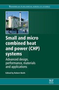
Energy storage systems can be classified in many ways, by type of storage medium, by size, applications or commercial status (Table 12.1).
Many energy storage technologies are modular, and assembled from a number of components arranged in series and parallel. By its nomenclature, a battery is a collection of cells - the largest batteries assembled are in the order of tens of MW and hundreds of MWh, although most would be in the size range up to about 10 MW. Capacitors for energy storage tend to be grouped in smaller installations by power rating, and their storage capacity is limited. Electrolysers and fuel cells have been installed in MW size installations and, where there is large-scale fuel storage, the energy capacity can be measured in hours or days. Flywheel systems are also becoming larger. While industrial machines are rated in tens or hundreds of kW, installations of 10 or 20 MW are now under construction.
12.3 Applications of electrical energy storage
An energy storage device can be used to:
• provide power over short durations - seconds or minutes
• provide power over longer durations - minutes to hours or days
In order to keep a power system stable, generation must equal demand plus losses at all times. If generation falls, voltage and frequency drop, machines slow down, lights dim and eventually the system fails. At the other extreme, if generation exceeds demand and losses, the effects can be catastrophic.
A short duration interruption, even of an AC cycle (0.02 seconds at 50 Hz) can cause damage to computers, computer controlled equipment and precision machinery. Customers protect themselves against this occurrence by installing uninterruptible power supplies (UPS).
12.3.1 Types of uninterruptible power supply (UPS)s
Most commercial UPS systems consist of three sub-systems:
• an energy storage device, usually a flywheel or battery with an AC/DC power conversion system
• a separate generator which can be started to provide resilience of supply beyond the energy storage capacity of the storage device.
These can be installed to protect a single load, such as a computer, or to protect larger installations such as offices, shops or factories.
UPS systems to protect domestic computers are readily available from computer stores. They are installed between the domestic wall socket and the computer using standard plugs. Care needs to be taken to ensure that the UPS has the power capacity (kW) required to sustain the computer, or other device, as well as the energy rating to provide resilience against the duration of the power interruption. Typically this is of the order of 15 minutes, which is sufficient to close down a computer safely. Increasing the discharge duration increases the cost of these systems significantly. Modern computers are now often rated at lower powers than earlier machines, thereby either increasing the resilience time, or decreasing the cost of the energy storage system. These devices are usually based on valve regulated lead acid batteries, which provide a cost effective solution with low maintenance.
In many instances, a commercial or industrial scale UPS is supplemented by a standby generator, which is started after 1 or 2 minutes. This continues to supply the load for as long as there is fuel. For some of those larger installations, flywheels are used as an alternative to batteries. The flywheel might be integrated with the standby generator, which improves reliability by directly linking the mechanical systems.
While UPS solve the technical problems caused by interruptions to the power supply, some equipment requires a very stable, continuous power supply with no fluctuation to the expected smooth voltage profile. This higher performance is achieved by specifying increased standards for the power conversion system. For many small systems, this will be hidden from the user, but will be of significance for medium and larger-scale projects.
12.3.2 Types of energy storage technologies for integration with CHP systems
Smaller-scale systems in use for small- and micro-CHP projects are unlikely to make use of larger-scale technologies such as pumped hydro or underground compressed air energy storage directly, but if the CHP systems are connected to the grid network, they will, of course, be making indirect use of such systems. This point is often overlooked - that introducing electricity storage at any point in the network has an impact through the system. The conceptual difficulty is that finance does not always follow the flow of electrons in an equitable manner. The location and ownership of the storage device are prime considerations in the financial analysis of the storage device. The installer or operator may not gain an economic return on the whole value of the investment.
12.3.3 Mechanical systems
Flywheels have been available as UPS for many years, but some developers are now offering these as energy storage devices in their own right. Flywheels are typically characterised as either high speed or low speed. As the energy storage capacity is proportional to the square of the rotational speed, increasing the speed is an effective method of increasing the capacity of the system. Flywheel systems would have a high cycle lifetime, low maintenance costs and would have simple requirements in terms of siting. The interface to the power network is usually based on a variable frequency power conversion system, which can accommodate changes in the flywheel speed, but producing a constant frequency power output.
Although the maximum energy storage capacity of the flywheel is fixed by the parameters of the rotary mass, the power rating and hence the discharge time can be varied, so that it is feasible to consider flywheels with a low power rating but a discharge time measured in terms of minutes or even hours.
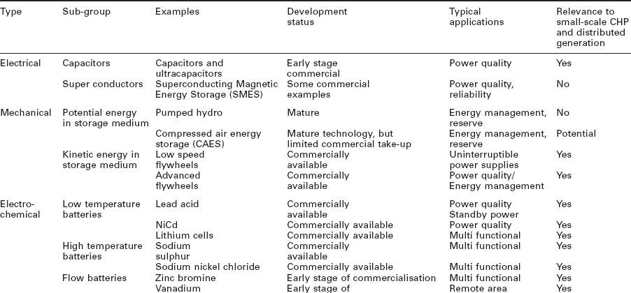
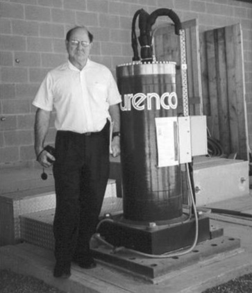
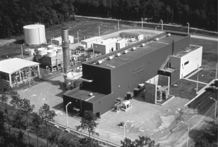
Figure 12.1 shows a matrix of large scale flywheels operating in combined mode connected to the power network to provide 1 MW of power for frequency regulation. Figure 12.2 illustrates the size of a single 50 kW flywheel system. There are currently two large-scale compressed air energy storage (CAES) plants operating. Figure 12.3 shows the 110 MW CAES plant built in McIntosh, Alabama, USA that has been operating since 1991. Although large scale (100 + MW) compressed air systems are considered out of scope for small-scale CHP applications, MW scale compressed air installations are now being considered. EPRI expects to run a demonstration MW scale CAES plant using air storage in above ground pipes (derived from the oil and gas industry). Figure 12.4. illustrates a typical system diagram.

12.4 Applications for combined heat and power (CHP) systems
12.4.1 Establishment scale
CHP systems are usually installed on premises where there is a constant heat load, and, ideally, reasonably constant electrical load. Many CHP systems installed in the past 20 years have considered the electricity generated as a useful byproduct and not the main reason for installing the plant. The purpose of integrating energy storage is to optimise the generation and onsite consumption of electricity with the use of the storage device and energy exchanges with the network. The analysis is dependent on a number of factors:
• ownership and operation of the CHP plant
• ownership and operation of the energy storage plant
• whether the installation is a net product or consumer of electricity
• the commercial arrangements for import and export of electricity.
The costs may be considerably lower to install a new CHP/storage system than retrofitting storage to an existing installation. More recently, with the drive towards sustainability, more businesses and organisations are striving to become energy neutral or self-sufficient in energy. Such considerations can influence decisions, making it possible to consider the use of storage even when the investment is not rewarded by payback.
12.4.2 Domestic scale
For small installations, such as houses or apartment blocks, installing storage may have severe impacts on the economics of the heating system. As CHP installations may receive feed in tariffs for on-site production under the arrangements for micro power, there is little incentive to use on-site storage unless the import purchase price exceeds the value of the feed in tariff when multiplied by the inverse of the efficiency of the storage device.
The Japanese research group CRIEPI (central Research Institute of the Electric Power Industry) is undertaking active development work to introduce battery energy storage into all-electric houses which use heat pumps as the heating source. The control system will also be adapted to permit the introduction of electric and plug-in hybrid vehicles.
12.4.3 The economic case
If such CHP systems are not eligible for feed-in tariff support, then the financial calculation is simplified, and the benefit can be expressed in terms of the difference between the value of exported power against the price of imported power.
Such economics ignore the following:
• capital cost of the energy storage equipment
• capital cost of the installation
• annual operating costs (maintenance, insurance, rates, rent of additional land)
Integrating CHP with electrical energy storage is therefore only likely to happen if there are very simple trading arrangements (for example, based on net metering), or if the installation is large enough to justify either trading costs directly or when traded through an aggregator.
12.4.4 Costs of storage
The cost of an energy storage installation is dependent on a number of factors. For a relatively simple installation, such as a domestic UPS system where a device may be purchased from a catalogue and installation costs are low, it is easy to estimate the overall project cost. As soon as the project enters a bespoke phase, costs have a tendency to increase as specialist skills and equipment are required.
Costs will be lower when established technologies such as lead acid batteries or ice storage are used. Advanced batteries, such as lithium chemistries, high temperature batteries or flow batteries will have much higher costs. The costs of the power conversion system and switchgear may be between 50 and 100% of the cost of the battery.
12.5 Grid services applications and relationship to combined heat and power (CHP)
Grid services fall into two broad groups
• localised services, such as voltage control
• system services, such as frequency regulation and reserves.
Distributed generation can have positive and negative effects on the operation of a distribution network. Traditionally, distribution networks have been installed on the basis of a radial system, with power generated centrally and distributed to users through the distribution network. V oltages were set so that the consumers at the end of each distribution line were served with an electrical supply that was within the regulated limits (230 V ± 10%). Adding distributed generation to the extremities of the network can significantly alter the voltage at points on the network. The power electronics associated with a storage device can be used to mitigate these effects, maintaining the voltage within the defined limits. However, such services are the responsibility of the distribution company and a private owner of storage would not normally be expected to provide these services.
The transmission system operator has a duty to maintain the system frequency within defined limits. In order to do this, the system must be kept in balance, that is, generation must match demand, plus losses. The system is balanced for energy across trading periods (30 minutes in Great Britain) and constantly for power. In Great Britain, the National Grid Company instructs generating companies and demand customers to increase and decrease their supply and demand to maintain the balance. These participants use a variety of different contracts depending on the type of service being provided. Examples of these services include:
An owner of a CHP plant could contract for these services, but the addition of a storage plant makes it easier to provide those services without necessarily imposing on the operation of the CHP plant. In many instances it may be possible to provide these services for a few hours each day.
12.6 Electrical vehicles
There is considerable interest in the use of electric vehicles as a means of decarbonising the power network. The assumption is that the energy used to charge the electric vehicles will be generated from the sustainable resources. Operators of CHP plant, especially where there is a variable demand for electricity, may be able to balance the heat and electrical load, particularly at off-peak periods, by charging electric vehicles. Many sustainable resources, such as solar photovoltaic and wind are variable and not continuous and it is appropriate to consider the use of storage as a means of not spilling electricity. However, this should be balanced against the use of the grid as a sink for such electricity and as a source for generation.
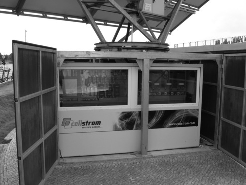
An example of a battery system is shown in Fig. 12.5. The vanadium battery is charged from an associated PV panel. The stored energy is used exclusively to charge a fleet of electrically powered motorbikes.
12.7 Large-scale and small-scale storage - conceptual planning
Many different models can be postulated for the installation of energy storage and these also relate to its integration with CHP. Whilst the most impact is obtained by placing the storage as close to the end consumer as possible (as this aggregates the benefit of storage from the consumer back to the source of generation), economies of scale may mean that the specific costs of installing storage at the consumer’s point of connection is high. Savings could be made by introducing storage at higher levels in the distribution network, not only in specific equipment and capital costs, but also in trading and other commercial costs.
12.8 The development and application of thermal storage
This chapter has considered the case of using a storage medium as the intermediate stage between electricity charge and discharge. It is quite possible to use a storage device which uses thermal storage as the intermediate medium, and such thermodynamic cycles are under development.
One modification is to use heat as the charging method, and this is adapted in the molten salt storage system typically installed in conjunction with solar concentrating thermal plants (see Fig. 12.6). The concentrated solar radiation is used to raise the temperature of a molten salt, which is contained in well- insulated containers. During periods of darkness, the molten salt is used to raise steam which drives a turbine to generate power.
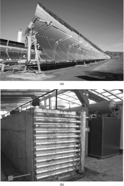
Fig. 12.6 (a) Parabolic trough collectors, Almeira Spain. (b) Experimental solid media storage unit with a capacity of 400 KWh (source: SPIE), (source: SPIE).
Another modification is to use the heat directly, without recourse to generating electricity. This reduces the efficiency loss of the overall system. This is similar to the principle of the night storage heater, which was popular in Britain in the 1960s. Bricks were heated by electricity at night, and an arrangement of vents was used to allow the heat to warm the house over the next 17 hours. The premise was economics - the electricity generated at night from base load generating plant (coal and nuclear) was at lower cost than supplying power from peaking plant during the afternoon and early evening peak. Customers received an incentive in that night time electricity was at lower cost than the normal day time rate. Domestic thermal storage is still available, and the aesthetics and performance of the devices have improved considerably. Where a self-producer of electricity has a heat requirement, it would be quite feasible to use thermal energy storage as a means of time shifting energy production to suit the consumer’s demand profile.
A further variation is to use off-peak - or surplus - electricity to produce ice. During peak periods, air can be blown over the ice or through cooling loops to cool buildings, saving on the use of the full air conditioning load.
Some commercial buildings, such as supermarkets and cold stores could also use the large thermal version of deep freezers and refrigerators as a proxy store.
Thermal storage appears to the grid as a demand customer and can therefore contribute to the supply of resources by shutting off demand, and also to respond to high frequency events by switching on, when necessary. A recently announced development in the United States links a 5 MW concentrated solar power plant with a thermal storage plant at the ‘Solar Zone’ which is part of the University of Arizona Science and Technology Park. This large project has an estimated cost of more than $32 million.
12.9 Future trends
The smart grid is seen as a way of integrating all forms of generation and demand to operate the network in the most efficient manner. Some include a vision of control of industrial loads, even at and before domestic level and the incorporation of a smart meter which has time of day pricing. At the distribution and transmission level the transformers, switchgear and lines and cables are controlled to ensure that lines are run under optimum conditions and variable generation is used effectively.
This complex vision can be simplified by the use of storage at key points in the network. American Electric Power (AEP) propose the introduction of Community Energy Storage (see Fig. 12.7) where storage is located at the local distribution transformer. The store acts as a local buffer, aggregating distributed generation and demand on the circuits downstream of the share.
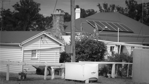
Fig. 12.7 Community Energy Storage: 5 kW, 20 kWh Community Energy Storage by Redflow Technologies Ltd.
The Community Energy Storage is controlled by the network, charged and discharged to provide a stable power flow from the utility into, or out of, the battery. AEP see that this buffer will protect this network from the large and variable power flows that may arise from the introduction of electric vehicles and domestic charging.
12.10 Sources of further information and advice
Electricity Storage Association: www.electricitystorage.org
Department of Energy and climate change: www.decc.gov.uk
Feed in tariffs: see DECC announcement http://www.decc.gov.uk/en/content/cms/news/pn10_010/pn10_010.aspx (accessed 1 February 2010).
Energy Saving Trust: www.energysavingtrust.org.uk