
Organic Rankine cycle (ORC) based waste heat/waste fuel recovery systems for small combined heat and power (CHP) applications
Abstract:
This chapter describes the principle of the organic rankine cycle (ORC), suitable heat sources, the benefits of ORC when compared to the water vapour process, the different ways to build an ORC, a historical review, some present day manufacturers and guidelines to estimate efficiency and specific price. ORC is a power plant process, where the working fluid is an organic fluid instead of water. It can be used to produce electricity and heat from various fuels and heat sources, such as biogas, waste heat, biomass, etc. The typical electric power range of ORC is from 140 kW to 2500 kW.
9.1 Introduction
The organic Rankine cycle (ORC) is a Rankine process, where the working fluid is an organic fluid instead of water, which is used in conventional steam power plants. ORC power plants are often operated in cogenerating mode, i.e., the thermal power discharged by the condenser is used in an industrial process or to heat environments (these plants are called combined heat and power (CHP) plants). Alternatively, by condensing the working fluid at a lower temperature, only electricity can be obtained (condenser heat is rejected to the atmosphere or to lake/sea water).
9.2 Principle of the organic Rankine cycle (ORC) process
The Rankine cycle is named after William John Macquorn Rankine (18201872). The conventional steam power plant cycle is called the Rankine cycle, where the working fluid is water. If the heat source is at high temperature, and the design power sufficiently high, water is an excellent working fluid. It has exceptional thermal stability, excellent heat transfer properties, it is non-toxic, non-combustible, inexpensive, has zero ODP (ozone depletion potential) and zero GWP (global warming potential). However, if the heat source is at low or medium temperature, and/or if the power capacity of the plant is low, selecting an organic fluid instead of water as the working fluid gives several benefits.
The principle of the ORC has been well known for decades. Most of the present ORC plants are based on conventional turbine technology, which includes shaft seals, a reduction gear, an air cooled generator and a lubricating oil system. Thermal energy is transferred to the process either directly, or by means of a thermal-oil circuit. More recently a new turbo-generator concept has been developed and brought to commercial realization: the pump, the electrical generator and the turbine share a single shaft, while the working fluid also serves as the lubricant and coolant for the electrical generator. This system configuration allows for completely hermetic design, with no need for shaft seals or a separate lubrication system.
The main idea in most ORC plants is to produce electric power from a relatively low temperature heat source and/or relatively small amounts of waste heat or heat produced by burning limited amounts of fuel difficult to use in other processes. For low temperature waste heat applications, ORC technology provides many benefits compared to the conventional steam Rankine process. Typical low temperature heat sources for ORC applications are geothermal heat and the waste heat from combustion engines, gas turbines and many industrial processes. Typical high temperature sources with limited capacity are burning of biomass, landfill gas, or biogas and heat generated by concentrating solar collectors. The greatest number of ORC plants are probably sold in the power range 300-2000 kW, but they are also made in the range 100 to 22 000 kW, and there are also low efficiency micro-ORC in the power range 0.5-5 kW.
One of the most notable advantages of a Rankine cycle employing an organic substance as the working fluid is that the fluid remains in the superheated vapour phase throughout the entire expansion in the turbine, thus avoiding the well-known problem of condensation in the low-pressure stages typical of all steam turbines. A recuperator is therefore normally used to de-superheat the vapour entering the condenser, and to preheat the fluid entering the boiler. Figures 9.1 and 9.2 illustrate the technology of typical ORC power plants dating back to the 1980.
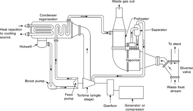
9.1 Working principle of a conventional ORC process without thermo-oil circuit (Sundstrand 1983). The diagram shows how the liquid process fluid is pumped from the condenser hotwell to the regenerator to be preheated, and from the regenerator to the vaporizer where it is converted to vapour by means of hot heat source gases. This high temperature and high pressure organic vapour expands in the turbine and produces electricity by means of a generator. After exiting the turbine the vapour goes through the regenerator (where it is de-superheated) to the condenser, where it is converted back to a liquid state.
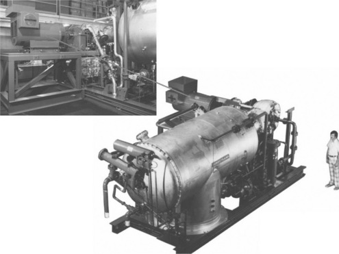
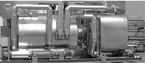
9.2 Process shown in Fig. 9.1 in reality. Upper detail shows generator and gearbox, lower detail turbine, recuperator and condenser. Power 500 kW (Sundstrand 1983).
9.3 Typical process heat sources and operating ranges for organic Rankine cycle (ORC) systems
9.3.1 Industrial waste heat
In many industrial processes significant amounts of hot gases are produced, and the heat cannot be utilized. If this heat could be converted into electricity, significant savings can be attained (see Table 9.1). Figure 9.3 shows an application, where hot gases from several ceramic kilns are collected and introduced to an ORC plant.
Table 9.1
Some suitable present-day industrial waste heat sources, and economical feasibility according to one ORC-manufacture (Vescovo 2009)
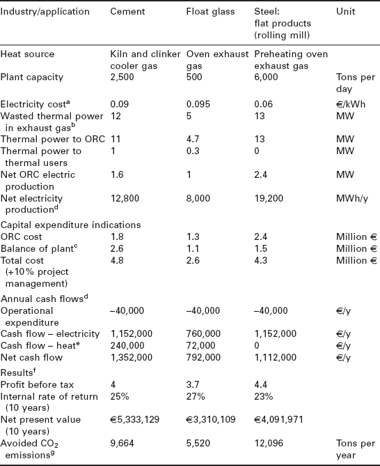
aThese values include incentives if any; differences are due to total power installed, nation, etc.
bAssuming to cool down the gas to 150/160 °C.
cIncluding heat recovery exchangers and civil works - estimated by reputable suppliers.
dAssuming 8,000 operating hours/year.
eAssuming a heat valorization of circa 0.03 €/kWh.
fAssuming discount rate of 5%.
gAssuming 0.63 kg of CO2/kWh electric and 0.2 kg of CO2/kWh thermal (from CH4 combustion).
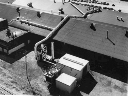
9.3 ORC power plant (500 kWe), heat source of which are hot gases collected with pipes from several ceramic kilns. Early 1980 design (Sundstrand 1983).
9.3.2 Gas turbines and combustion engine exhaust gases
Exhaust gases from gas turbines and internal combustion engines can be recovered effectively by means of an ORC power plant, thus considerably increasing the overall energy conversion of the combined system, much like in modern large combined-cycle power plants. In such large gas turbine plants and also in very big motor power plants, high efficiency is obtained by using a steam process with several pressure levels. However, if the gas turbine power is below 5-7 MW and motor power below 8-12 MW, a water vapour process is difficult to achieve with good efficiency, and an ORC process may be more favourable. An example of an ORC power plant run with exhaust gas from a 2 MW gas engine is given in Fig. 9.4. The minimum gas turbine power for present day economically feasible ORC is probably about 0.5 MW and minimum motor power probably about 1 MW (future development may decrease these limits). Many of these smaller motors are run with biogas, which makes this application particularly favourable for the environment.
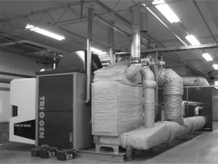
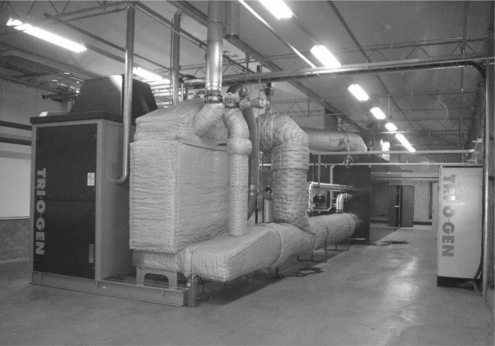
9.4 ORC power plant (145 kW) run with exhaust gas from a 2 MW gas engine installed in 2008. Left, ORC process module; right, the exhaust gas boiler (Tri-O-Gen 2010).
9.3.3 Biogas from industrial and municipal waste streams
The gas produced in landfills is similar to biogas, but may contain components that are harmful for gas turbines and combustion engines. Larger plants may be provided with a gas cleaning system, and this gas can be used without problems in gas engines or in gas turbines. However, if the amount of gas in a landfill is small, it can be used without cleaning directly as a heat source for an ORC plant. An example of an ORC plant run with unclean landfill gas is given in Fig. 9.5. Of course, efficiency is lower compared to gas motor (in the order of 20-22% instead of 30-40% for gas motors).
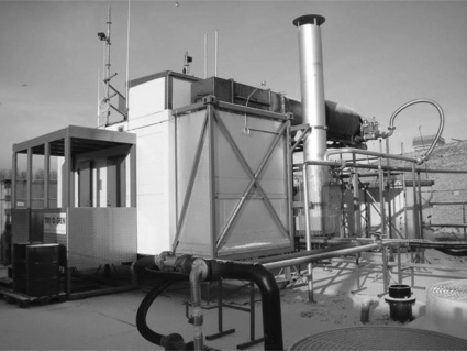
9.5 ORC power plant (150 kW) run with unclean landfill gas (Tri-O-Gen 2006).
9.3.4 Biomass in agriculture and in forestry
In agriculture and forestry huge amounts of combustible waste are produced, such as bark, wood chips, sticks, straw, etc. However, usually it is not economically feasible to transport this waste over long distances. Thus a power plant that can utilize the biomass near the production site is required. In many cases there is not enough biomass for a conventional steam power plant (minimum size ca. 3 MW), and thus an ORC plant is a good solution. The economical feasibility of the biomass plant depends largely on the collecting and storage costs of fuel. The optimal range for this cost limits the capacity of the power plant to quite low values in many cases. Figure 9.6 shows how electricity and district heat can be generated from biomass.
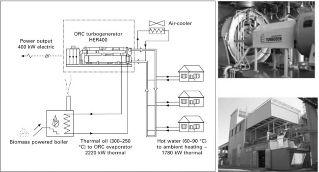
9.6 Diagram showing production of electricity and district heat from biomass (Bini and Manciana 1996). Top right: biomass ORC plant in Kopfling, Austria 200 kW; bottom right: biomass ORC plant in Althofen, Austria 1500 kW (www.turboden.eu).
9.3.5 Using geothermal heat
High temperature geothermal heat may be used in the water vapour process (there are a number of different processes). However, if the temperature level and/or amount of heat power are limited, an ORC process may be a better alternative (see Fig. 9.7). Also, if geothermal steam is ‘dirty’ and/or sour, an indirect ORC process is more favourable. Thus a very large number of ORC plants are in use in geothermal applications, two examples of which are shown in Fig. 9.7.
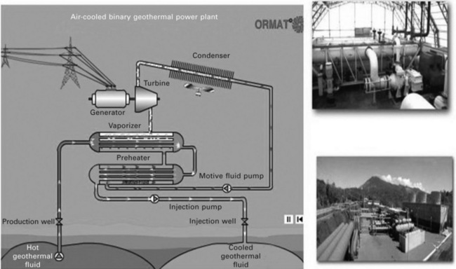
9.7 Principle of ORC using geothermal heat as heat source, and two example plants in Iceland (top right) and in Costa Rica (bottom right) (www.ormat.com, Ormat 2008).
9.3.6 Micro-ORC in distributed energy system
By selecting a suitable working fluid and by using high speed technology with a hermetic turbogenerator, ORC power plants may be realized in very small power sizes (below 5 kW) with reasonable or even good efficiency. Ormat has already for decades made small very low efficiency ORC units for special applications (Bronicki 1988) (see Fig. 9.8). In these cases reliability is the only requirement and a mtbf (mean time between failures) of over 200 000 h has been obtained.
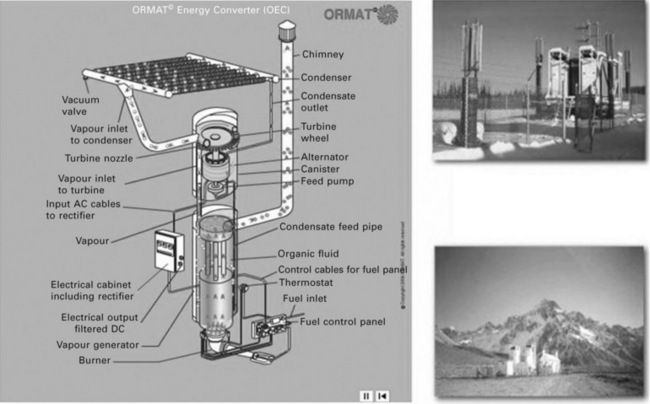
9.8 Principle of micro-ORC plant for special applications, and two example plants: pipeline gate valve station in Alaska (top right) and Telecom link in Chile (bottom right) (www.ormat.com).
However, by manufacturing the micro-ORC unit in large series, it should be possible to obtain a price level that would make it suitable as a household CHP power plant, that is, it would be like a reversed heat pump. Local fuels, like biogas or biomass could be used as a heat source to produce electricity and heat for a private house or a farmhouse (Colonna and Pasquale 2008). This type of project is in the starting phase.
9.4 Benefits and disadvantages of organic Rankine cycle (ORC) process as compared to waterbased systems
9.4.1 Benefits of low heat of vaporization
The typical ORC process is presented in the temperature-entropy diagram in Fig. 9.9. The process is idealized by neglecting pressure and heat losses. The steps are:
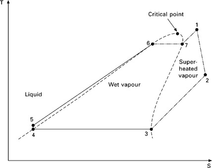
9.9 Simplified ORC process in temperature-entropy diagram. It should be noted that typical organic vapour remains superheated in expansion, in contrary to water vapour, which is moist after expansion.
• expansion of vapour in turbine (from 1 to 2)
• removal of superheating in recuperator (from 2 to 3)
• pressure increase of the liquid (from 4 to 5)
• preheating of the liquid in recuperator and boiler (from 5 to 6)
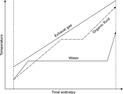
When comparing ORC and water vapour processes, there is a clear difference in relative magnitude of vaporization heat. If the temperature of the heat source gas is limited (e.g. exhaust gas), this high vaporization heat limits the obtainable pressure and superheating in the case of water vapour process. When the organic fluid is selected properly (vaporization happens near the critical point), the relative magnitude of vaporization heat is small, and we can obtain significantly higher average temperature and thus higher process efficiency. This is presented in Fig. 9.10.
9.4.2 Benefits of low enthalpy drop in turbine
The specific enthalpy drop of organic vapours in turbine is small when compared to water vapour. This makes turbine design easy. In most cases a single stage turbine with reasonable tip speed is sufficient. The specific enthalpy drop in the high efficiency turbine stage is about the square of tip speed. In the case of water vapour, three turbine stages are required in most cases in order to obtain high efficiency. In addition to this, if the power is small, the optimum speed of a water vapour turbine may be unrealistically high. Turbine power is mass flow multiplied by specific enthalpy drop. Thus low enthalpy drop means high mass flow and high volumetric flow, which makes the turbine design stage easier (larger relative blade height). We may introduce specific speed Ns of the turbine stage:
where ɷ is the angular velocity of shaft, qv2 is the volumetric flow at turbine outlet and Δhs is the isentropic drop of specific enthalpy. In order to obtain good turbine stage efficiency, Ns must be higher than 0.3-0.5 (depending on turbine design). This condition is easily obtained with organic vapour with reasonable shaft speed, but in the case of water vapour (high enthalpy drop, low volumetric flow) we must either use a very high rotational speed, or accept low Ns or use a multistage turbine. Also, a multistage turbine may be necessary in the case of water vapour in order to avoid too high a tip speed of the turbine rotor.
The disadvantage in ORC turbine design is the low sound velocity in organic fluids. Thus, despite the reasonable low gas velocities, supersonic velocities cannot usually be avoided in single stage ORC turbines (Hoffren et al. 2002, van Buijtenen et al. 2003, Turunen-Saaresti et al. 2006, Colonna et al. 2008). This is becausse, for example, 250 m/s is clearly subsonic for air, but supersonic for most organic fluids. Velocities in this range must be used in turbine in order to obtain good efficiency.
Despite the supersonic velocity problems, it is easy to make a small ORC (e.g. 25 kW) with a high efficiency single stage turbine, whereas water vapour process must be made in most cases with a three or four stage turbine, thus resulting in a practical minimum size of 2000-3000 kW.
9.4.3 Benefits of good dielectric properties
Most organic working fluids have good dielectric properties. This means that generator windings may be exposed to the organic vapour, in contrast to water, which is a poor insulator, and may cause a short circuit in windings.
9.4.4 Disadvantages of ORC with large size plants
In large power plants, the specific price is lower for the water vapour process than for the ORC. Thus, if the power plant size is big enough, say 4000-5000 kW or bigger, the water vapour process is in most cases cheaper and more efficient than the ORC. If power is high enough, we can afford a multistage turbine, and relatively large vaporization heat problem can be avoided by using several pressure levels (e.g. large combined power plants use up to three pressure levels in order to maximize the average temperature level in the water vapour process using exhaust gas heat from a gas turbine). Limiting power depends on the heat source temperature. If the heat source temperature is very high, the water vapour process may be favourable down to 2000 kW; if the heat source temperature is low, the ORC may be favourable up to 5000-10 000 kW.
9.5 Selection of working fluid for organic Rankine cycle (ORC) systems
9.5.1 Thermal stability
The theoretical thermal efficiency of ORC is not very much affected by the working fluid. It is almost entirely defined by the temperature difference between condenser and heat source. However, many practical properties of the working fluid affect the obtainable efficiency. One is the thermal stability. The process fluid should not decompose in the temperatures used, or this decomposition should be extremely small. Otherwise the main products of decomposition, non-condensing gases, fill the condenser and decrease efficiency. Other harmful products of decomposition (depending on fluid) are carbonous particles, or glue-like polymers (siloxanes), or in the case of fluoro-containing fluids some toxic compounds. For most organic fluids, temperatures higher than 400 °C cause problems. Decomposition is affected by many factors, e.g. certain metals may act as catalyst. Thus the best way to find the limits of thermal stability of a fluid is to run it a long time in a test loop, where conditions and duration of high/low temperature correspond approximately to the real process (Calderazzi and Colonna 1997).
9.5.2 Volumetric flow
In most ORC plants it is favourable to use a single stage turbine. In order to obtain good efficiency, the specific speed of the turbine should be within certain limits. Because the specific enthalpy drop does not vary very much with typical organic fluids, the easiest way to adjust the specific speed is to select suitable volumetric flow at the turbine outlet, see Equation 9.1. This does vary very much with different fluids, depending on the vaporization pressure. For small ORC plants it is favourable to select a fluid with high volumetric flow, because this will ease the turbine design (not too high speed).
9.5.3 Pressure in condenser
If the pressure in the condenser is higher than the atmospheric pressure, leakage of air into the process is impossible. However, volumetric flow in the turbine will be low. If the pressure in the condenser is very low, air will easily leak to the process, and vacuum suction must be used in order to avoid pressure increase in the condenser, resulting in a decrease in efficiency. Also, one problem is that air (oxygen) is a catalyst for thermal decomposition; even ‘safe’ temperatures in the evaporator might become problematic if oxygen is present there.
9.5.4 Environmental aspects
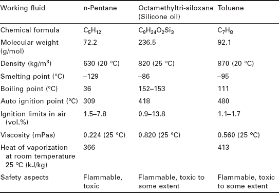
In general, working fluid should have zero ODP (ozone depletion potential) and low GWP (global warming potential). Preferably it should be non-toxic and non-combustible. Also, of course, it should be inexpensive. Usually all the requirements cannot be met simultaneously. Thus many working fluids used are, for example, combustible and also toxic to some extent. Table 9.2 presents the properties of some working fluids used in present day plants.
9.5.5 Dry or wet expansion
Most organic fluids experience dry expansion in the turbine, and their degree of superheating will increase. This makes the control of the vaporizer easy: in most cases it is sufficient to ensure that the vapour entering the turbine is dry; complex control of the degree of superheating is not needed.
9.6 Process system alternatives
There are several alternatives in building an ORC plant.
• The vaporizer may be run directly by the heat source fluid, or by a thermo-oil circuit.
• The turbine may be connected directly to the generator, or a reduction gear used.
• The feed pump may be connected directly to the turbine, or a separate, multistaged pump run with an electric motor may be used.
• The generator may be air cooled or exposed to the working fluid vapour and cooled with it.
• The generator may be connected directly to the network and run at synchronous speed, or it may be connected through an inverter, which permits variable speed of the generator.
• The process may be hermetic, or provided with one or several shaft seals, having potentially some leakage.
• The turbine bearings may be lubricated with process fluid, magnetic bearings may be used, or the shaft may be provided with external, oil lubricated bearings (usually the working fluid cannot be mixed with oil; significant reduction of thermal stability may result).
• The condenser heat may be used for heating purposes (CHP), or condenser heat may be rejected to the air (or water).
The thermo-oil circuit has been widely used, for example by Turboden, GMK and also Ormat in certain applications. The benefit is that in most cases the customer is able to build the thermo-oil circuit, and the ORC manufacturer can connect the ORC energy converter directly to this circuit. Several thermooils can be used, e.g. Therminol 66. However, if the heat source is at limited temperature, this extra circuit decreases the ORC vapour temperature and thus decreases the efficiency. Also, the maximum permitted temperature of thermo-oil, if it is lower than that of the ORC fluid, may limit the maximum temperature of the circuit. The thermo-oil circuit also increases investment expenses to some extent.
If the working fluid is exposed directly to the boiler, the boiler must be particularly designed for the organic fluid. In this design process one important target is to avoid hot spots at the sides of the working fluid (if heat source gas is very hot). This means that the ORC manufacturer must either also supply the boiler or at least participate in the boiler design. An obvious benefit is a more simple system and higher efficiency if the heat source temperature is limited.
The conventional system in turbine design is to use a high speed turbine, shaft seal, reduction gear and air-cooled, synchronous generator. However, the turbine shaft seal may be a difficult component, and an oil system is needed for the reduction gear.
In so-called high speed technology solution, turbine, generator, and feed pump are connected directly to each other, and provided with process fluid lubricated bearings. In this case the generator windings are exposed to the organic fluid vapour, and the generator is connected to the network through an inverter. Because of the lack of outgoing shafts, the turbogenerator can be made fully hermetic. Probably the first of this type of plants made were the micro-ORC plants supplied by Ormat at the beginning of the 1960s (Bronicki 1988). Larger high speed technology plants with high pressure ratio circuits were developed by Lappeenranta University of Technology (Larjola 1984, 1988), resulting later as a commercial plant in co-operation with Tri-O-Gen b.v. (van Buijtenen et al. 2003, van Buijtenen 2009).
9.7 Background and summary of commercial development and exploitation
9.7.1 Historical review of early development stages 1960–1984
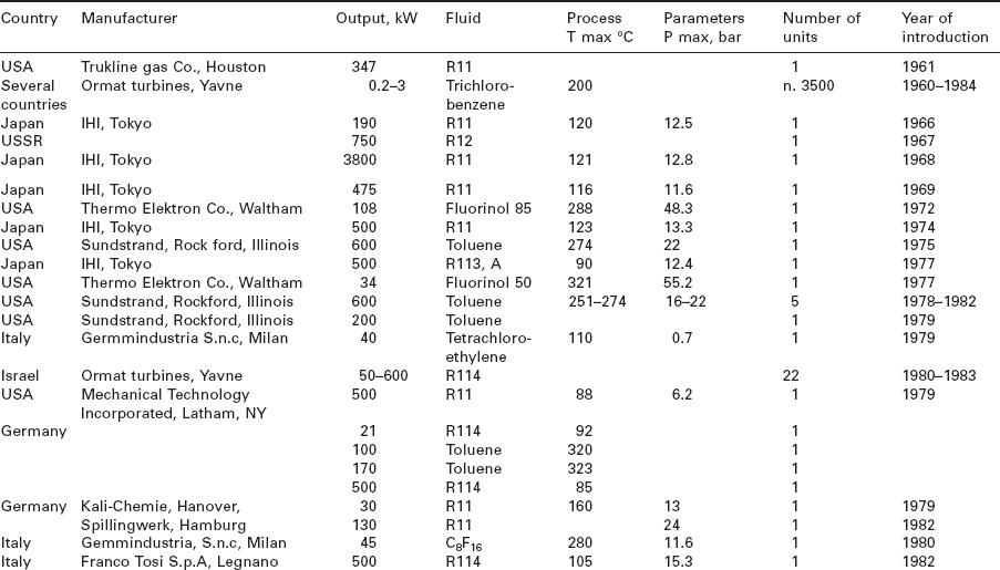
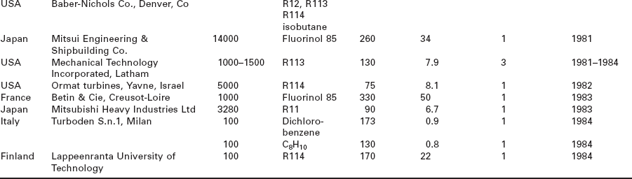
The basic idea behind the ORC is quite old. The first plants were built at the beginning of the 1960s. The majority of the plants built between 1960 and 1984 are shown in Table 9.3. It can be seen that two of the companies, Ormat and Turboden, are still major ORC manufactures today. Excluding chloro-fluoro-carbons, the most popular working fluids at that time were chlorobenzenes, fluorinol 85 and toluene.
9.7.2 Examples of current technology provided by present day manufacturers
Several hundred ORC plants have been built during the last decade. Because nowadays it is very important to decrease CH4 emissions and to use all waste heat in electricity production, it is expected that the number of ORC plants will further increase quickly. CH4-rich gases (biogas, landfill gas) produced by the decay of organic material should be burned, or biomass should be burned before it produces CH4, and in this conversion oRC is very suitable, as stated earlier. Some present day ORC manufacturers are described below in alphabetical order:
GMK - Gesellschaft für Motoren und Kraftanlagen mbH, Germany
GMK was founded in 1994, and it makes ORC plants for industrial waste heat, geothermal and biomass applications. Heat transfer from heat source to ORC power conversion module is made with a thermo-oil circuit (see Fig. 9.11). Typical power range is from 500 kW to 5 MW. GMK has supplied about 10 ORC plants (see Fig. 9.12) (situation May 2010) (http://www.gmk.info/).
9.11 One typical ORC power conversion module from GMK (http://www.gmk.info/).
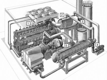
9.12 Example of GMK ORC plant connected to diesel engine. 1. Diesel exhaust gases heat up the thermo-oil in heat exchanger 2, and thermo oil, circulated by pump 4 vaporizes the ORC working fluid in vaporizer 5. ORC power conversion module (turbine, generator, condenser, feed pump) is situated between vaporizer and diesel engine (http://www.gmk.info/).
Ormat Technologies Inc
Ormat was founded in Israel, and was making micro-ORC plants as long ago as 1960, introducing production of industrial size ORC plants in 1980 (Bronicki 1988). Ormat concentrates mainly on geothermal applications, and its main factories are nowadays in the US (its head office is located in Reno, Nevada). The total number of ORC plants supplied is over 2000. Ormat also makes quite large plants, and ORC plants using biomass heat or industrial waste heat are mainly connected to their heat source by thermo-oil circuit (see Fig. 9.13). Power of energy conversion modules delivered range from 200 kW to 22 MW (http://www.ormat.com/).
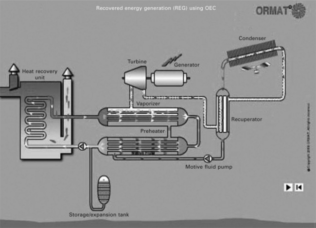
9.13 Flow diagram of Ormat ORC plant producing electricity from industrial waste heat or from biomass. Thermooil is preheating and vaporizing the working fluid in separate heat exchangers (http://www.ornat.com/).
Tri-O-Gen B.V., Goor, The Netherlands
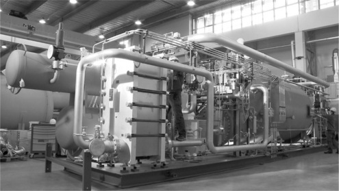
Tri-O-Gen made its first plant in 2003. However, its roots are deeper, as mentioned earlier: the high speed design is based on development work at Lappeenranta University of Technology, where the first prototype of this type was made in 1984. Since 2004 Tri-O-Gen has supplied about 10 plants mainly to biogas and landfill gas applications (situation May 2010). Plants are based on high speed technology and on hermetic circulation process. No thermo-oil circuit is used; working fluid vaporizer is run directly with the heat source gas (see Fig. 9.14) (http://www.triogen.nl/).
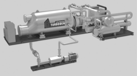
9.14 ORC power conversion module from Tri-O-Gen (left). Heat source gas (in this case exhaust gas of a biogas engine) is introduced directly to the process fluid vaporizer (grey in the middle) (Trio-O-Gen 2006).
The principle of the ORC based on hermetic high speed technology is shown in Fig. 9.15 (van Buijtenen 2009). Heat source gas vaporizes the working fluid in the vaporizer, hot vapour expands in the turbine, and superheating is removed in the recuperator, which preheats the fluid going to the vaporizer. Turbine, generator and feed pump are directly connected to each other, and this common shaft is provided with process fluid lubricated bearings. Because of high speed, the feed pump needs only one stage, and the generator, cooled with the process fluid, is small compared to the power. The process is hermetic, because there are no shaft outlets. The size of the standard power conversion module is 160 kW, but it may be provided with several parallel turbogenerators, thus giving a power range up to 800 kW.
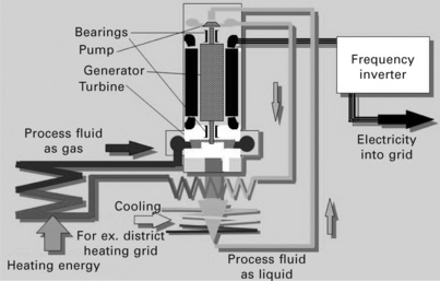
9.15 Process diagram of the Tri-O-Gen ORC plant based on high speed technology (Tri-O-Gen 2006).
Turboden S.r.l., Brescia, Italy
Turboden made its first plant in 1984. The design is based on the thermo-oil circuit. Heat is introduced with thermo-oil to the power conversion module (Figs 9.16 and 9.17). The turbine is reported to have very high efficiency. In many references the heat source is biomass. Typical plant size is from 400 to 2000 kW. Turboden has supplied in total 139 ORC plants for biomass applications, 13 for waste heat applications and 3 for geothermal applications (situation March 2010). Nowadays Turboden is a part of Pratt & Witney Power Systems (http://www.turboden.eu/en/home/).
9.16 Power conversion module of typical Turboden ORC plant (Bini and Costa 2010).
9.17 Schematic of Turboden power conversion module (Bini and Costa 2010). Typical flow diagram of Turboden plant in biomass CHP application is presented in Fig. 9.6.
9.8 Efficiency and typical costs for current organic Rankine cycle (ORC) plants
It is difficult to give accurate figures for ORC plant efficiency, because it is very dependent on cycle upper (T2) and cycle lower (T1) temperature. Upper temperature may vary significantly due to heat source temperature, and lower temperature may vary due to condensing connections: is the condensing heat used for district heating (CHP), or is it rejected to ambient air or to sea or lake water? Thus a good method is to calculate Carnot efficiency on the basis of known upper and lower temperature, and then compare this to the given ORC plant efficiency ƞORC (= electric power/input heat power). This ratio may be called the ORC process efficiency ƞpros and is a measure of plant quality. Suppose that the upper temperature of the working fluid is 320 °C → T2 = 593 K, and the lower or condenser temperature is 50 °C → T1 = 323 K. Supposing that the given ORC plant efficiency is 21%, it can be obtained from Equation 9.2 that ƞpros = 46%.
In general the ORC plant efficiency is much lower than the theoretical maximum Carnot efficiency. In most cases ORC plant efficiency is in the order of 18-22%. The above mentioned ƞpros is in the range of 44-50% for many plants. Thus ƞpros can be set at 50% in order to estimate ƞORC for a particular case. It should be noted that if a thermo-oil circuit is used, the upper temperature of thermo-oil must be at least 5-10 °C higher than T2. And T1 must be at least 5-7 °C higher than the upper temperature of the condenser cooling water.
Some manufacturers give specific prices in public papers (Duvia et al. 2009, van Buijtenen 2009, Vescovo 2009) for ORC. The specific price is very dependent on what is included and what the heat source is. If the heat source is biomass, and a burning system is included, expenses are of course higher than if the heat source is industrial waste heat. Speaking in very rough figures, in favourable conditions, specific prices of complete plants fall in the range €1600-4500€/kWe (year 2009). However, before a real feasibility study is made, one should get a quotation for that particular case.
9.9 References
Bini, R., Costa, A. Turboden marketing materia. 2010.
Munich, Germany, 22-23 October Bini, R., Manciana, E. Organic Rankine cycle turbogenerators for combined heat and power production from biomass. Energy conversion from biomass fuels; current trends and future systems. 1996.
Bronicki, L. Experience with high speed organic Rankine cycle turbomachinery. Proceedings of Conference on High Speed Technology, 21-24 August 1988, Lappeenranta, Finland. Lappeenranta University of Technology, Department of Energy Technology, Publ. No ENTE. 1988; D-15:47–61.
Calderazzi, L., Colonna, P. Thermal stability of R-134a, R-141b, R-13I1, R-7146, R-125 associated with stainless steel as a containing material. International Journal of Refrigeration. 1997; 20:381–389.
Colonna, P., Pasquale, D. Micro-ORC turbogenerator: a viable option for domestic cogeneration. Delft University of Technology, Process and Energy Department, Delft, The Netherlands, Technical Report ET-2272. April 2008.
Colonna, P., Harinck, J., Rebay, S., Guardone, A. Real-gas effects in organic Rankine cycle turbine nozzles. Journal of Propulsion Power. March-April 2008; 24:282–294.
Hamburg Duvia, A., Guercio, A., Rossi di Schio, C. Technical and economic aspects of biomass fuelled CHP plants based on ORC turbogenerators feeding existing district heating networks. Biomass Conference 2009. 2009.
Heinimö, J., Jappinen, E. ogy in distributed electricity production (in Finnish). Lappeenranta University of Technology. 2005. [Research report EN B-160].
Heinimö, J., van Buijtenen, J.P., Backman, J., Ojaniemi, A., Malinen, H. High Speed ORC technology for distributed electricity production. 2nd World conference on biomass for energy, industry and climate protection, Rome, Italy. May 2004; 10–14.
Hoffren, J., Talonpoika, T., Larjola, J., Siikonen, T., Numerical simulation of real-gas flow in a supersonic turbine nozzle ring. ASME Journal of Engineering for Gas Turbines and Power. Volure April 2002; 124:395–403. http://www.gmk.info/. http://www.ormat.com/. http://www.triogen.nl/. http://www.turboden.eu/en/home/index.php
Larjola, J. ORC-plant with high-speed gas lubricated turbogenerator. VDI-Berichte 539: ORC-HP-Technology (proceedings of VDI-Seminar: ORC-HP-Technology, 10-12 September 1984, ETH Zurich). 1984; 697–705. [Dusseldor].
Larjola, J. ORC power plant based on High Speed Technology. Proceedings of Conference on High Speed Technology, 21-24 August, 1988, Lappeenranta, Finland. Lappeenranta University of Technology, Department of Energy Technology, publ. No ENTE. 1988; D-15:63–77.
Ormat Technologies, Inc. 2008 Sustainability Report
Tri-O-Gen. Marketing material. 2010.
Turboden company presentation. Codice doc09Z00158_e 2010;
Paper No. GT2006-91118, ASME Turbo Expo, Barcelona Turunen-Saaresti, T., Tang, J., van Buijtenen, J., Larjola, J. Experimental and numerical study of a real-gas flow in a supersonic ORC turbine nozzle. May 2006; 8–11.
van Buijtenen, J.P., Larjola, J., et al. Design and validation of a new high expansion ratio radial turbine for ORC application. 5th European conference on turbomachinery, Prague. March 2003.
van Buijtenen, J.P. The Tri-O-Gen organic Rankine cycle: development and perspectives. Journal of the IDGTE Power Engineer. 13(1), March 2009.
Vescovo, R. ORC recovering industrial heat; power generation from waste energy streams. Cogeneration and on site power production. March-April 2009.