
District and community heating aspects of combined heat and power (CHP) systems
Abstract:
This chapter focuses mainly on the district and community heating aspects of small CHP systems, the heat sources and control systems and contains issues to be considered before a new district heating system is to be established. Further, this chapter contains some of the preconditions for getting started and overall design considerations. These experiences are based on projects established primarily in Denmark and the UK and with case studies from Aars in Denmark and Lerwick in Shetland.
14.1 Introduction
District heating (DH) is a very old principle and was already used by the romans some 2000 years ago. Of course, it has developed since then, but in principle it remains a central heating system expanded to contain more than just one house, and the heating is today transported from boiler to house in pre-insulated pipes. It is a relatively simple system and the principles are easy to understand, but still district heating is often called one of the best kept secrets because it is buried under the ground and very few people know about it. Even in Denmark, where 60% of all houses are connected to district heating systems, very few people knows about district heating in detail and many do not even know from where the heating comes. One of the reasons for this situation is that very few problems arise with the system, the limited space demand and almost no maintenance in the home. When designed according to the recognized recommendations, the system is extremely robust and the number of hours when there is no heating is very limited. In areas with district heating there are only a limited number of individual stacks and therefore the air quality is high and nobody thinks about the heating of the house. It is just something you have as long as you pay the bill and can be compared to buying your water or your electricity and who knows where these services come from?
One of the main reasons for establishing district heating is that heating of houses and preparation of hot tap water do not need high-level energy carriers like fossil fuels or electricity but can use low-level sources as surplus energy from, for example, power production and industrial processes. When used as a byproduct from power production, the fuel efficiency is more than doubled, from typically 35—45% in power plants to 85-95% in combined heat and power (CHP) plants.
Further, the district heating system gives a better fuel flexibility and enables a number of local resources such as straw, wood, different waste products, biogas, sun, wind, geothermal energy, etc., to be used for heating. This is good for the local economy and the overall environment as the energy efficiency is improved and the emissions from the heat generation can be controlled and limited due to the central generators and monitoring possibilities that exist in a centralized installation of a certain size range.
District heating water has a further advantage: it is easy to store and, with a storage tank, daily variations in heat consumption can easily be handled. It is therefore not necessary to have generation capacity available for the peak demand and the heat production can be stable or, if there is surplus energy from a process at any time, it can be stored in the storage tank.
14.2 How to get started
In Denmark, district heating covers more than 60% of the housing stock which is among the highest rates in the world. The last 40% of Danish houses are in natural gas areas, are in rural locations or in small towns with fewer than 100 houses. They are supplied by individual boilers with natural gas and oil but also wood pellets and straw boilers are used. The high connection rate to district heating was helped along by the two energy crises in the 1970s when oil prices more than doubled, and a political wish to become less dependent on oil and coal from abroad. Energy planning was introduced in all major towns and cities in Denmark, where areas were dedicated to district heating and some cities also introduced compulsory connection to DH systems.
Many of the big DH schemes were owned and operated by municipalities but often the establishment of a new district heating system was started by individuals who had the energy, charisma and enthusiasm for the idea of having a local and flexible heat supply. DH is comparable in cost to other heat sources and often cheaper, but some of the small gas-fired CHP plants have experienced a change in the preconditions with higher gas prices and lower electricity prices and they can only put the deficit on the heating cost.
Preconditions for getting a DH system up and running include:
• getting customers committed to take the heating
• a heat source that can provide competitive energy prices
• political support as the municipality has to give permits for the establishment of the system and they do also have control over a number of buildings that could become good customers
• financial resources to handle the investments which are long term and with a long payback period
• an organization with knowledge of handling a project like this, both setting up the preconditions for the project, the design and operation, and developing a plan.
When a DH project starts, it must be recognized that it is as long-term, ongoing project. You can finish your first, second and third stages, but you will never finish developing your DH system. When the system in the town is fully developed, you can start thinking about connecting to neighbours and connection to new heat sources or developing new heat sources. Lerwick and Aars are two good examples (explained in more detail in Sections 14.6 and 14.7) but almost every district heating company can improve or expand, and this will continue with the development of technology and knowledge.
14.3 Heat sources
The heat sources available for district heating have developed rapidly in recent years. Economy, environment and sustainability are important drivers when it comes to choosing the right heat source. In the 1960s and 1970s fossil fuels were cheap and easily available and there was limited focus on the environment. However, first the energy crises in the 1970s and then the slow depletion of natural gas (Denmark will not be self-sufficient in gas from around 2016) and the global warming commitments have changed the focus. Now sustainability and security of supply are the most important factors when setting up a new system, but also in developing an existing system.
With the development of wind farms the electricity market will experience frequent imbalances, therefore even electricity can be a sustainable heat source when used at the right time. Large-scale electric boilers or heat pumps can help balance electricity consumption with generation, and DH systems with storage tanks can easily adapt to these variations.
14.3.1 Size considerations
It is evident there is a considerable difference between summer load and winter load, the actual difference depending on the temperature and wind factors, but in the UK and Denmark the factor of heat demand is probably 4-5 times larger during winter compared to summer. During the summer the need for heating is very limited and heat produced is primarily used for heating tap water and heat loss from the pipe system.
When designing the plant, a general principle is the heat source with the lowest production price has the highest investment cost. Therefore the plant should consist of a base plant able to supply, e.g., 60% of the peak load and a peak and reserve plant covering the last 40%. A rule of thumb, 60% of the peak load will cover 90% of the yearly energy production and therefore it is of little importance what the production cost is with the peak load installations.
14.3.2 Examples of heat sources
The following is a short introduction to a number of possible heat sources.
Biomass
Biomass is often available locally and can consist of straw, wood chips, wood pellets, shredded roots, and other residues from forestry and farming. Most commonly these plants are heat only but there are a few CHP plants.
Biogas
In Denmark there are only a few plants using biogas, but in Germany and other parts of Europe the number of such plants is increasing. They provide gas from landfill sites, composting facilities and anaerobic digestors accepting a range of green and wet wastes. Biogas, which is mainly methane based, can be used in, e.g., gas engines producing both power and heating resulting in a very high efficiency.
Waste to energy
Energy from waste is very common in Denmark and provides a considerable amount of the district heating. Most plants are built as CHP installations, but because of the very corrosive flue gases the steam generators can only operate to steam temperatures around 400—440 °C. The efficiency is therefore relatively low if these plants are only producing electricity and even an optimized plant will not achieve more than ~ 30% efficiency. However, the combination of heat and power production can give efficiencies above 95% and with flue gas condensation even above 100%. This is possible because the efficiency is calculated with the lower heating value and these fuels contain some moisture.
Fossil fuel
Typically fossil fuel plants use light fuel oil or natural gas. These plants are used as peak and reserve load installations as the investment cost is low and the operation relatively simple. Natural gas is also used in CHP plant with gas engines but these are often smaller plants and have relatively high heating prices as the gas prices have risen and electricity prices gone down.
Other heat sources
The other heat source in Danish district heating systems are geothermal, with only a few plants running but more are currently under development. Waste heat from industrial processes and solar heating are growing fast at the moment and these systems can count as an energy sawing initiative.
14.4 Pipework installation issues and design considerations
District heating pipes have the prime purpose of distributing the energy to customers with the lowest possible heat and pressure. The physical layout of a district heating network has to be based on the location of the consumers as well as geographical conditions of the area to cover ground levels of the landscape, etc. At the same time the pipes have to be protected against corrosion and damage from other utilities, etc.
The standard pipes are today insulated with polyurethane foam and have containment pipes of steel or polyethylene. Branch pipes are often flexible and the dimensions depend on the differential pressure available over the length of the pipe and the overall condition of the DH system. If the DH system is old, it can contain some dirt and therefore very small pipes (< 16 or 20 mm) should be avoided but new branch pipes are made down to 12 mm inside diameter in the media pipe. These very small diameters gives very little heat loss and a cold pipe takes limited time to heat up, but if the main pipe contains some dirt the clogging of the branch is a risk factor.
Older pipe systems are of different quality and, depending on the water quality and general operating conditions, they can be either in good condition or very bad condition. To clean the water particle filters are installed as part flow filters, but if a pipe is clogged there is no alternative but to flush the pipes. New pipes are of a high quality and there will be no problems with them if they are installed according to the specifications and not damaged by other utility companies. Some problems have been caused by cable diggers who are just ploughing their cables into the ground with little or no consideration for other pipes.
Regarding the installation of pipework in the ground, there can be problems in installing pipes in streets and built-up areas as there are usually many existing services already laid in the ground. On some occasions re-routing of existing systems is necessary or the heating pipework may have to be installed deeper. It is also possible to drill a 'tunnel' and drag the pipe through. These problems become more difficult with bigger pipe diameters, but the pipes used are flexible and tough and can be manipulated satisfactorily. It is true to say that there are usually some problems, but potential consumers have always been connected regardless of such problems.
14.4.1 Pipe size considerations
The optimal sizing of the main pipes is difficult as the pipes have a lifetime of 40 years and therefore need to be designed for a future load compared to when they are installed. The initial pipe design has to include a development plan for the main pipes going from the plant to the areas being supplied, and new areas to be connected must include a plan for how and when customers are to be connected. When an area is developed it is therefore a big advantage if the connection rate is high from the beginning as the heat loss is then optimized. The installation cost is also a lot cheaper if consumers are connected when the mains pipes are installed. To get people connected, customer information and promotion is therefore essential and often combined with a discount rate for connections carried out during the initial installation of the pipes. If the connection rate is too low, the system will operate with a high heat loss but, if the connection rate on the other hand is too high compared to the connection plan, the pipes might need to be upgraded before the end of the lifespan.
To get some heat load on the system from the beginning, it is a good idea to concentrate on the larger consumers such as hospitals, swimming pools, sports centres, schools and public buildings and areas developed with new housing, and initially connect them as they will ensure a good flow in the pipes. If the areas with the larger consumers are developed first, it also ensures that the system will work and a reasonable base load is applied to the system. If there is little knowledge about district heating, it is also an advantage to have proven the system with an initial installation before large-scale expansion, as mouth-to-mouth promotion is often one of the most efficient ways of getting new customers.
14.4.2 Consumer education
As the capacity of the pipes is linked closely to the temperature difference between flow and return, it is important to get the consumers to cool the water and extract as much heat as possible. The heat loss in the return pipes also depends on the temperature, so the consumers are therefore an integral part of the DH system and it is important to get them to follow some simple rules to make the overall system operate with the lowest losses and cost. These rules include the following.
• Install radiators designed for District Heating, e.g. 60-70 °C flow temperature and return at 30—40 °C.
• Use all the radiators in the house to ensure the best cooling of the DH water.
• Keep doors closed to rooms where you want lower temperatures.
• Avoid temperatures lower than 16 °C when operating with lower temperatures during night-time. This is to avoid big changes in heat demand during the day, as the maximum heat demand is what pipes and heat sources are designed for. Heat loss from the house is very limited at lower temperatures, therefore nobody gains much by going to lower house temperatures. Basically it is more economical to operate at the system design duty than at low load.
Further, a good customer relationship can be an advantage as an aware customer keeps an eye open and if there are, e.g., leaks in the system, they can help find them. If an aware customer sees an area with no snow during the winter period or steam coming from underground, they would know this could come from a DH pipe and be an important informant for the operators.
14.5 Control system and consumer installations
The commitment of the system is to ensure all costomers have sufficient heating. The temperature, differential pressure and static pressure need to be sufficient to heat the house and make hot water within the safe temperature parameters at all times.
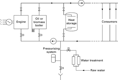
In the design of a district heating network, the following basic items must be observed and considered. Figure 14.1 outlines the general overall principles of a DH supply unit with a CHP unit as the base unit and oil-fired boiler as backup, the pressurising system and supply of treated water. Figure 14.2 outlines the principles of a DH supply unit also including a heat storage tank for optimized operation of the producing units and able to average the daily variations. Figure 14.3 outlines a standard consumer installation with direct space heating by means of radiators and hot tap water supply through a plate heat exchanger. The supply to customers can also include a heat exchanger to ensure the water in the radiators and the distribution pipes are separated. For example, in Aars it is a direct system as shown in Fig. 14.3, but in Lerwick, Shetland, all customers are supplied through a heat exchanger.

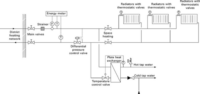
14.3 Standard consumer installation with direct space heating by means of radiators and hot tap water supply through a plate heat exchanger.
14.5.1 Pressurizing and static pressure
The pressure in the district heating network must be calculated and designed on the basis of the ground levels of the area covered. The pressure in the pipes must ensure there is water coverage at the highest locations under all operating conditions, preventing air and raw water intake at defect connections or consumer installations. Normally the pressure in a distribution network is also kept below 10 barg at all locations. If the network needs to cover areas with a large variation in ground level it has to be separated into pressure zones by large heat exchanger units or by booster pumps and pressure reduction valves. The 'static pressure' is the pressure that remains in the district heating network when the system is at rest, e.g. with all pumps stopped. The static pressure should be kept at a level that gives approx. 1 barg at the highest ground level in the network.
The pressurizing system is in most cases brought as a pre-assembled unit with a pressure-less reservoir, with pumps to add water to the network at low pressure and mechanical valves to drain water at high pressure. The design capacity of the pressurizing system is based on the water volume in the network, enabling the system to drain water at a sufficient rate when the whole network is heated up from standstill, and again add sufficient water if the system cools down as a result of a break down, lack of heat power, etc. It is also essential that the reservoir of the pressurizing system is designed to prevent oxygen uptake in the water.
Differential pressure
The differential pressure between flow and return pipe in the network creates the flow rate through the customer installations. The lowest differential pressure at the individual customer depends on the pressure loss in their internal installations, but normally 0.3 bar is sufficient.
The differential pressure in the network is established by the main pumps installed at the DH plant. The main pumps are designed for highest possible energy efficiency on the loads that occur in the highest number of running hours during the year. In the design process loads for summer and winter are considered as well as the redundancy or backup philosophy, and the number of pumps is determined, i.e. two 100% capacity pumps, or maybe three 50% capacity pumps.
The location of the main pumps also has to be considered in the system layout. Normally the best solution will be to locate the pumps in the return pipe pumping through boilers, heat exchangers, etc., as this will keep a pressure on the producing units securing against steam generation in the system.
14.5.2 Heat storage tank
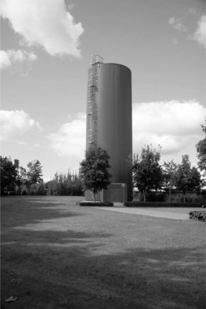
In DH networks based on CHP units, biomass boiler units or maybe surplus energy from local wind turbines, it is of great benefit to incorporate a heat storage tank to equalize the difference between production and demand in the network. CHP units can be operated at full load during periods with high electricity prices, and relatively slow reacting biomass or waste-to-energy boilers often run optimal at constant load, regardless of the peak loads in the network. The heat storage tank is in its simplest form an insulated pressurized tank with diffusers at the top and bottom to make the flow in and out of the tank at a low velocity, thus building up a layer division between hot and cold water (Fig. 14.4).
14.5.3 Water quality in the network
In order to reduce risk of corrosion, leaks, deposits and bacterial growth in the district heating network, it is essential to establish and maintain the right quality of the circulated water. In smaller DH networks the makeup water is normally prepared in a pre-assembled softening unit where the calcium and magnesium salts in the water are exchanged with sodium salt which do not cause the disadvantages of hard water. Adding special chemicals raises the pH value in the water and prevents growth of bacteria. The pH value is monitored and additional chemicals dosed on a continuous basis, keeping the pH value at approx. 9.5.
14.5.4 Flow temperature
The flow temperature in the DH network should be kept as low as possible to reduce the losses throughout the year. The temperature should, on the other hand, be high enough to ensure sufficient heating and hot tap water for customers located at the furthest point in the network.
Space heating
Space heating depends on the dimensions of radiators, and district heating often requires larger radiators than for a traditional boiler system as the DH system is more efficient when the return temperature is as low as possible. These radiators are, though, only marginally bigger and can be combined with under floorheating as they can operate at flow temperatures as low as 30 °C. This will ensure a very low return temperature. A traditional consumer boiler installation often operates with a high return temperature as this is needed to protect the boiler itself from corrosion, and the 'losses' from both flow and return pipes is within the premises thus all adding to the heating. Losses from district heating are mainly located in the exterior network and this is reduced by low return temperatures. So when including existing consumer space heating installations, there might be a need to increase radiator sizes and there must be focus on removing all bypasses in the installations.
Hot tap water
The hot tap water must be kept above 55 °C to limit the risk of bacteria growth. This is often the dimensioning criteria for the district heating temperatures during summer operation and consumer installations should also be designed with consideration to where in the network they are located. If close to the plant the temperatures and pressure are higher and direct heat exchangers can easily be used, but at some distance the temperatures will be lower and the differential pressure also lower therefore, so a hot water tank might be the best solution as the operation of the DH system needs to take account of the designed consumer installations to avoid customer complaints.
14.5.5 Customer billing system
Different billing systems have been used in DH systems through the ages, previously based on items such as consumed cubic meters, area of heating surfaces, floor area, etc. Due to temperature drop in the widespread network, different flow temperatures were available to consumers thus giving a different energy price. The availability of cheap electronic energy meters have nowadays resulted in energy-based billing giving the same price per energy unit to all customers, normally combined with a standing charge based on size of installation and maximum heating demand. Also the customer's ability to return the water at a low temperature has in recent years been integrated in the tariffs. It is important to get the right balance between the different elements of the billing system to support incentives such as cooling, and still to keep the district heating energy price attractive compared to other sources.
14.6 Case study: Lerwick, Shetland
Designed in 1998, installation started in 1999 with main pipes to some parts of the town where the main customers and some of the larger ones were located, such as hospitals, swimming pools, sports centres, schools and public buildings and areas developed with new housing. This system is one of the most successful district heating systems in the UK and during its 10-year life span has now covered most of the town of Lerwick with more than 1000 customers. The system started as a result of heat from a 6.5 MW Energy from Waste plant built during the same period as the initial design and establishment of the DH system.
The main drivers were the Shetland Islands Council and the Shetland Charitable Trust ensuring capital. The Trust had funds accumulated from oil activities from the 1970s and was allowed to invest funds to benefit the Shetland economy. District heating schemes are very capital intensive requiring a large investment at the start. This tends to be the main obstacle to the development of such schemes when payback is over a long term. The most difficult task to retrofit a district heating scheme in an existing town in the UK is to obtain low return temperatures. Buildings were originally designed on a 82 °C supply and a 71 °C return. As the quality of customers' systems was questionable it was decided that there would be no direct feeds into a building heating system so that heat exchangers would be required, meaning the supply temperature would have to be above 87 °C. In addition the connection rate was expected to be low to start with until the scheme proved itself, so 95 °C was decided upon to allow for heat losses. Whilst a return temperature of around 70 °C was anticipated in general, it was found that many systems were overdesigned and that they could run at lower temperatures. An additional return line was run to the swimming pool which only needed to heat water to 30 °C and could lower the overall water from the town at a beneficial tariff. Initially the return was 65 °C but with new build and refurbishments over 10 years the return is down to 55 °C and it is hoped that this will be reduced to 50 °C over the next 10 years. Lowering the supply temperature to 90 °C is also a possibility.
The scheme had problems at the start with many objectors against the scheme primarily because it was expensive and an unfamiliar technology.
Falling oil prices did not make the marketing easy. By the following year oil prices had risen steeply and word of mouth on how good the system was starting selling the scheme, outstripping the local ability to connect, which produced a long waiting list. By 2010 the scheme had over 50 km of pipe and about 50% of the households within reach of the pipes connected. Most of the largest heat users are now connected. Non-domestic customers are 10% of the total but account for 60% of the heat consumed.
At two of the largest consumers, arrangements were made to take over the former boilers and keep them 'in mothballs' ready for use to feed into the scheme should flow from the Energy from Waste (EFW) plant or boilers have to be interrupted for maintenance purposes. As the installations had backup and were designed for worst case scenarios, they had sufficient spare capacity. It is anticipated that the lifespan of the boilers being kept in standby will be prolonged for many years. By 2006 the demand had grown so large that the backup oil boilers were consuming enough oil to meet morning peakloads to justify a 12 MWh thermal storage tank to store surplus heat during the early hours which was being dumped by coolers.
Right from the start electronic ultrasonic heat meters were installed. Whilst initially read from an external plug, the meters had radio modules installed that could relay most of the readings back to the office thus enabling accurate billing and monitoring of cooling by customers.
The scheme reached the output of the EfW plant in 2010 and numerous new sources of heat are being examined including front runner of wind turbines feeding into a large thermal storage tank. The potential increase of output from the EfW plant is also possible by the installation of an internal water jacket provided more waste becomes available. Whilst the scheme has brought environmental benefits in reducing emissions and landfill, it is the economic benefits that initially justified the scheme and these have been exceeded. With the reduction in imported fuels where money would have left the islands, reduced maintenance and capital costs of large customers and jobs created, economic returns (after deducting all costs and adding resultant benefits) of between 15 and 25% have been achieved.
14.7 Case study: Aars, Denmark
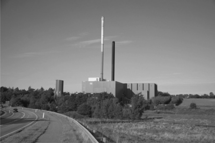
The DH system was established in 1955 with initially 26 customers signing up to the system. The initiative was taken by some local entrepreneurs who could see the local benefits from investment in this plant. Low heating costs and a safe supply of heat was essential to develop the town further. The first system was based on fossil fuels and the pipes were steel pipes in concrete ducts insulated with Rockwool and Leka stones, but from the 1960s the first pre-insulated pipes were installed. Oil was the main heat source, but the oil crisis influenced the design towards the development of alternative fuel sources and the Municipality and the District Heating Company developed plans for a Waste to Energy (WtE) plant (Fig. 14.5). The first WtE plant (6.5 MW) was established in 1985 and commissioned in 1986 together with a coal-fired (5 MW) peak and reserve boiler. The site was in the outskirts of the town and a transmission pipe was installed to supply the former oil-fired boiler stations.
As the town expanded, the new areas were connected to district heating via a heating plan and therefore the connection rates in these areas were 100%. This was very efficient and gave a good utilization of the pipes and the base load from the WtE plant was used during most of the year. The waste amount also increased and in 1995 the next incinerator was installed increasing the capacity by more than 100%. This was a combined heat and power line and included a 3 MW turbine together with a 10 MW heat capacity. This capacity was too big for the summer load and coolers had to be installed as there was a waste treatment obligation. The summer load only allows one incinerator to be in operation and the challenge was then to further expand the district heating area. Compulsory connection was approved by the municipality and during a 10-year period all houses within the district heating area had to connect. Now all houses in Aars are connected and in 2009 a neighbouring town was connected via a 7.5 km transmission pipe (Fig. 14.6).

14.6 A twin pipe with two different dimensions. This is the 7.5 km transmission pipe between Aars and Hornum in Denmark
The transmission pipe has a special design to both take account of heat loss and pumping loss. It is a twin pipe with a DN125 in the flow giving high flow velocity and a DN150 in the return giving low pressure loss. Both pipes are built into the same insulation dimension as a DN150/DN150 pipe to ensure optimum insulation, resulting in a temperature loss in the flow pipe of only 1 °C during winter operation in the 7.5 km long transmission pipe. The neighbouring town has a gas engine CHP plant and, in combination with the Energy from Waste plant in Aars, there is a possibility only to operate the engines when the electricity market is out of balance and giving high prices for regulating power. Further, a 1 MW electric boiler is installed and the purpose of this is to use some of the surplus electricity from the wind turbines. When operated it is at negative electricity prices, at down to - £150/MWh.
In total 4300 customers are now connected to the DH system and a few of the other neighbouring towns with gas engine CHP plants are also interested in connecting to Aars as the heating cost is low, there is still a little surplus energy during the summer period and the two incinerator lines could easily operate for longer periods. The project economies of these projects are to be investigated in 2010.
14.8 Future trends
14.8.1 Temperature optimization
To limit heat losses from the pipes, many DH systems are now introducing temperature optimization. The principle is to supply only the necessary temperature during summer and winter load most customers can operate their heating system with a flow temperature of 60 °C, but the temperature in the pipes depends on the flow rate and the insulation of the pipes. Therefore most systems have been operated on the safe side with too high temperatures resulting in unnecessary heat loss from the pipes. Computer programs can simulate the temperatures from the load situation and with control measurement the program can be balanced according to the actual conditions and afterwards the flow temperature and pressure from the plant optimized to the load situation.
14.8.2 Balancing of the electric grid
As a result of the introduction of wind farms and the unpredictable electricity generation, the heating systems can be used as load dumps when there is overflow in the electricity market. Electric boilers are easy to operate and can react quickly. Although they only generate, e.g., 1 MW of heat when using 1 MW of electricity, heat pumps could improve the power factor considerably but the regulating capability is not yet as good as the boiler, but a combination of the two systems could be a possibility.
14.8.3 Pipe dimensioning
Pipe dimensioning has mostly been relatively conservative, based on flow rates and velocity but branch pipes close to the boiler station could be made with smaller dimension because they have a high differential pressure available. This could also be used in the pipes instead of in a regulating valve.
14.8.4 Conversion from gas to district heating
Conversion of natural gas areas to district heating is one of the new trends in Denmark as the natural gas resources are running out and the government is now supporting these conversions. Heat pump solutions are probably the new heat source for rural consumers and those who are not close to a district heating system as they can be made to primarily use electricity at off-peak periods or even at electricity overflow from wind turbines.
14.9 Sources for further information and advice
• Danish Board of District heating, http://www.dbdh.dk/
• Danish District Heating Association, http://www.danskfjernvarme.dk/
• SHEAP Shetland Heat Energy and Power, District Heating Manager Neville martin, http://www.sheap-ltd.co.uk/
• COWI, http://www.cowi.com
• Aars District Heating, Director Jan Clement, homepage (only in Danish) www.aarsfjv.dk, or email [email protected], phone + 45 9998 8070.